ORIGINAL RESEARCH ARTICLE
DIRECT TORQUE CONTROL OF THREE PHASE INDUCTION MOTOR USING NEURAL
NETWORK-FUZZY LOGIC TECHNIQUES
*Mohanapriya, P. and Umadevi, K.
Assistant Professor, Electrical and Electronics Engineering, Excel College of Engg. & Tech.,
Namakkal, Tamil Nadu, India
ARTICLE INFO ABSTRACT
In this paper Fuzzy Logic and proposed Neural Network based Direct Torque Control of Induction motor are designed. A Back Propagation Neural Network is used in proposed method. The training patterns of Neural Network are extracted from Fuzzy Logic Controller based Direct Torque Control of Induction Motor. The operating characteristics of the proposed drive is compared with the Direct Torque Control and Fuzzy Logic Control to verify the effectiveness under various conditions by investigating the transient response for the step change of speed command and the load torque. The simulation results are provided in the MATLAB/SIMULINK Environment to demonstrate the effectiveness of the proposed methodology
Copyright ©2018, Mohanapriya and Umadevi. This is an open access article distributed under the Creative Commons Attribution License, which permits unrestricted use, distribution, and reproduction in any medium, provided the original work is properly cited.
INTRODUCTION
The controlling of dc drives are simple when compared to the ac drives. This complexity of control and estimation of ac drives arises due to dynamics of ac machines, variation in machine parameter and processing of feedback signals in presence of harmonics. Field Oriented Control (FOC) is widely used in industrial applications. But this method have serious disadvantage of parameter variation making it very sensitive to flux. To overcome these difficulties an advanced scalar control techniques for Induction Motor drives called Direct Torque Control (DTC) is gaining attention. This technique DTC employes the technique of selection of optimum voltage vector thereby controlling the torque and flux directly. The simplicity of DTC is ensured by the absence of co-ordinate transformation and current regulator; absence of separate voltage modulation block. But the drawbacks of DTC are slow transient response to the step changes in torque during start-up and high torque ripple. The drawbacks of DTC can be overcome by combining the fuzzy logic and Neural Network as they can handle the complicated non-linear characteristics through human expertise. The controller proposed in this paper is Neuro-Fuzzy Direct Torque controller which is weighed against the fuzzy based Direct Torque Controller. The proposed controllers possess better dynamic performance and precise speed control with good steady state characteristics. The proposed Controller has been simulated using MATLAB/SIMULINK environment and the results are provided to demonstrate effectiveness of the neuro-Fuzzy based controller. The organization of the paper as follows:(i) the machine modelling of induction motor,(ii) Direct Torque Control Technique using Fuzzy controller,(iii) Direct Torque Control Technique using Neuro-Fuzzy based controller,(iv) simulation results at different operating conditions,(v) conclusions.
Induction Motor Modelling
From the fundamental electrical and mechanical equation, the induction motor can be modeled. Among the different reference frames the voltage equations are expressed in the stationary reference frame.
*Corresponding author: Mohanapriya, P.,
Assistant Professor, Electrical and Electronics Engineering, Excel College of Engg. & Tech., Namakkal, Tamil Nadu, India
ISSN: 2230-9926
International Journal of Development Research
Vol. 08, Issue, 01, pp.18233-18239, January,2018
Article History:
Received 29th October, 2017 Received in revised form 13th November, 2017 Accepted 17th December, 2017 Published online 31st January, 2018 Key Words:
DTC, FL DTC, ANFIS, ANN DTC.
Citation: Mohanapriya and Umadevi. 2018. “Direct torque control of three phase induction motor using neural network-fuzzy logic techniques”,
International Journal of Development Research, 08, (01), 18233-18239.
An equivalent two phase circuit model of a three phase induction machine is derived and concept of the park’s transformation and the relation between three phase quantities and their equivalent two phase quantities are also discussed. For any arbitrary value of
,the transformation of stator ABC phase variables [FABC] to d,q stator variables [Fodq] is carried out through Park transform as,[Fodq] = [p ] [FABC] ……….(2.1)
1/2 1/2 1/2
[p ]=
3
2
cos
cos (
)
cos (
)
sin
sin (
) sin (
)
where
p
indicates the differential operator
dt
d
.A new variable called the zero sequence component is included with the d,q variables in order to handle unbalanced voltages and to invert park’s transform. The voltage balance equations are as follows
p
p
I
R
V
ds
s ds
ds
qs ………(2.3)
p
p
I
R
V
qs
s qs
qs
qs ……….(2.4)
p
p
I
R
V
dr
r dr
dr
qr ………(2.5)
p
p
I
R
V
qr
r qr
qr
dr ………(2.6)Where
ds Lss Lm 0 0 ids
dr Lm Lrr 0 0 idr
qs 0 0 Lss Lm iqs
qr 0 0 Lm Lrr iqrAt this stage
has not been defined and is quite arbitrary. Now
0
; this is called the stationary reference frame because the d, q axes do not rotate.0
p
i
dr ………..(2.8)r r qs
i
……….(2.9)r r
p
p
………(2.10)Substitute eqns. (2.8) - (2.10) in eqns. (2.3) - (2.6)
ds ds
s
ds
R
i
p
V
………..(2.11)qs qs
s
qs
R
i
p
V
………(2.12)
p
p
i
R
V
dr
r dr
dr
qr ………..(2.13)
p
p
i
R
V
qr
r qr
qr
dr ………...(2.14)………..(2.2)
………...(2.7)
Replacing the flux linkages (2.11) by currents using eqn (2.7)
v
R
i
L
p
i
r
G
i
………..(2.15)Where
v
v
dsv
drv
qs
T qr
v
……….(2.16)
i
i
dsi
dri
qs
T qr
i
………(2.17)Equation (2.15) can be rearranged in state space form for solution on a digital computer as follows:
i
B
p
v
i
r
G
i
……….(2.18)The electromagnetic torque in the stationary frame is given as
ds qs qs ds
e
i
i
p
T
2
2
3
………(2.19)
III. DTC with Fuzzy Logic Controller
[image:3.595.172.419.433.679.2]The control scheme of DTC involves comparison of torque with reference value defining the error torque state and comparison of stator flux with reference value defining the error flux state. Then according to the demands the stator voltage is determined using the above information. The fuzzy controller in DTC is established using seven level rule matrix show as Table 1. The three input fuzzy variables are the stator flux error, electromagnetic torque error and angle of stator flux. The output of the fuzzy controller is fed to the Artificial Neural Network. The inverter has been tuned by Space Vector Modulation (SVM).The above mentioned technique is used to reduce the phase interaction in the output waveform.
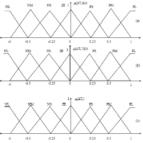
Fig. 1. The fuzzy membership functions of input variables (a) Torque Error, (b) Change in Torque Error and (c) Output Variable
III (i). Estimation of Errors
Both the flux linkage error and electromagnetic torque error can be estimated by difference between actual value of stators and reference value of stator by Fig 1. The flux and torque error can be expressed as
e e
e
T
T
T
* ……….(3.2)s s s
tan
………(3.3)The three fuzzy sets are then defined by the triangular membership functions. The implication is enhanced using Mamdani’s method while defuzzication is through Centroid method. The general expression for Centroid method is
dZ
Z
Z
Z
Z
out out
.
[image:4.595.210.390.205.381.2]0 ………(3.4)
Table 1. Rule Matrix for Fuzzy Controller
DTC With Neuro-Fuzzy Controller
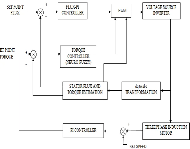
Direct torque Neuro-Fuzzy Controller is designed by combining fuzzy logic and Artificial Neural Network using ANFIS (Artificial Neuro Fuzzy Inference System).The parameters for the Neural Network are extracted from the Fuzzy Logic Controller. This controller eliminates the drawbacks of system with standalone Neural Network or Fuzzy logic Controller. The ANFIS has four Network layers which generate five functional blocks viz, rule based, data base, a decision making unit, a fuzzification interface and a defuzzification interface. The output of Artificial Neural Network is voltage space vector which replace switching table selector for PWM by Fig 2.
[image:4.595.146.456.518.760.2]Block diagram of proposed system
Fig. 2. DTC Technique based Neuro-Fuzzy system
Layer 1: The activation functions of this layer are fuzzy logic membership function. Layer 2: The minimum value of input is choosing in this layer.
Layer 3: The normalization of each input with respect to other input is carried out here.
Layer 4: This layer sums the entire input signal. The ith node output of this layer is a linear function of ith node output of third layer and ANFIS input signal.
The ANFIS structure is tuned by least square estimation (for output membership functions) and a back propagation algorithm (for output and input membership functions).This layer generates torque, flux and angle estimated from flux torque estimator. They are given as inputs to switching table which generates with in the appropriate voltage vector for the inverter which interns control the torque parameter of induction motor.
SIMULATION RESULTS
Direct Torque Control technique with Neuro-Fuzzy controller is compared with the FDTC (Fuzzy based Direct Torque Controller) and C_DTC (Conventional Direct Torque Controller) implemented induction motor drive under different operating conditions.
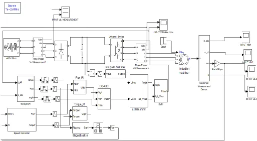
[image:5.595.43.557.263.544.2]Simulation Diagram of Proposed System
Fig. 3. DTC with Neuro-Fuzzy controller
Fig. 4a. Electromagnetic Torque response in C_DTC
[image:5.595.194.398.585.721.2]Fig 4b.Electromagnetic Torque response in FL DTC
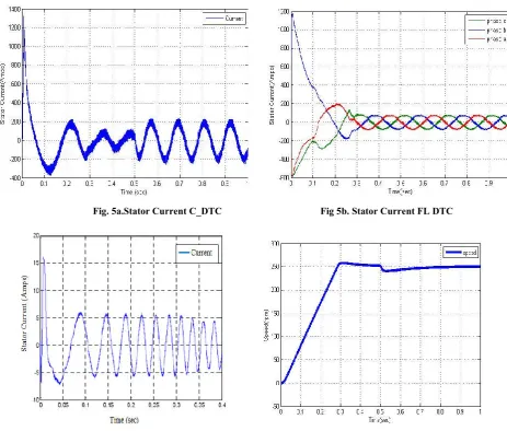
The Fig 5(a) shows the conventional response of stator current has very high ripple. But the steady state response of the sta current in FL DTC and proposed ANN DTC has negligible ripple and nearly sinusoidal waveform as shown in Fig 5(b, c).
Fig. 5a.Stator Current C_DTC
[image:6.595.45.544.56.230.2]Fig. 5c. Stator Current ANN DTC
Fig 4b.Electromagnetic Torque response in FL DTC Fig. 4c. Electromagnetic Torque response in ANN DTC
The Fig 5(a) shows the conventional response of stator current has very high ripple. But the steady state response of the sta current in FL DTC and proposed ANN DTC has negligible ripple and nearly sinusoidal waveform as shown in Fig 5(b, c).
[image:6.595.63.527.282.676.2]
Fig. 5a.Stator Current C_DTC Fig 5b. Stator Current FL DTC
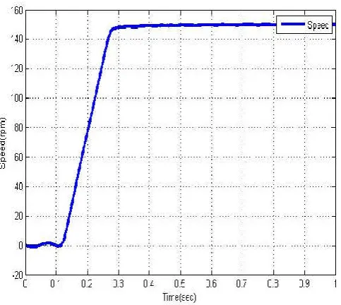
5c. Stator Current ANN DTC Fig. 6. Speed response in C_DTC
Table 2. Machine Parameters
Line Voltage(Volts) 440
Frequency(Hz) 50
Stator Resistance(mΩ) 14.85 Stator Inductance(mH) 0.3027 Rotor Resistance(mΩ) 9.295 Rotor Inductance(mH) 0.3027 Inertia(kg.m2) 3.1
Poles 2
Electromagnetic Torque response in ANN DTC
The Fig 5(a) shows the conventional response of stator current has very high ripple. But the steady state response of the stator current in FL DTC and proposed ANN DTC has negligible ripple and nearly sinusoidal waveform as shown in Fig 5(b, c).
Fig 5b. Stator Current FL DTC
[image:6.595.308.534.286.465.2]Fig. 7. Speed response in FL DTC
VI. Conclusion
In this paper a Fuzzy Logic and Artificial Neural Network based DTC of induction machine have been proposed. A better torque and flux response was achieved with the FLDTC and ANN DTC than the conventional DTC. The performance under various conditions has been tested by simulations. The main improvements shown are:
Reduction of torque and current ripples transient and steady state response. The motor reaches the reference speed rapidly and within minimum overshoot.
The Direct Torque Neuro-Fuzzy control strategy allows a higher dynamic behavior than the conventional and fuzzy based DTC.
VII. REFERENCES
Benaicha, S., Nait-said, R., Zidani, F., Nait-said, M.S., Abdelhadi, B. 2009. “A direct torque fuzzy control of SVM inverter-fed Induction Motor drive”,Proc.of the International Journal of Artificial Intelligence and Soft Computing, Vol. 1, Nos. 2-4, pp.259-270, 2009.
Bose, B.K. 2004. “ Modern Power Electronics and Ac Drives”, Pearson Education, 4th Edition.
Depenbrock, M. 1988. “Direct Self Control(DSC) of Inverter fed induction machine,” Trans.on IEEE - Power Electronics,vol.3,no.4,pp.420-429, Oct.
Gdaim, S., Abdellatif Mtidaa, Mohamed F. Mimouni, 2010. “Direct Torque Control of Induction Machine based on Intelligent Techniques”, Proc. Of the International Journal of Computer Applications Vol.10, Nos. 8.pp.29-35.
Habetler, P.G., Profumo, F., Pastorelli, M. and Tolbert, L.M. 1992. “Direct torque control of induction machines using space vector modulation,” IEEE Trans. on Industry Applications Society. vol.28,no.5,pp.1045-1053,Sep/Oct.
Joetten, R. and Maeder, G. 1983. “Control Methods for good dynamic performance induction motor drives based on current and voltages as measured quantities”, Trans. On IEEE Industry Applications Society, vol. IA-19, no.3, pp.356 - 363, May/June Krishnan, R. 2001. “Electric motor drives - Modelling, Analysis and control”, Prentice Hall.
Mir, S., Elbuluk, M.E. and Zinger, D.S. 1998. “PI and fuzzy estimators for tuning the stator resistance in direct torque control of induction machines”, IEEE Power Electronics, vol.13, no.2, pp.279-287, Mar 1998.
Takahashi, I. and Ohmori, Y. 1989. “High performance direct torque control of an induction motor”, Trans.on IEEE Industry Applications Societ,y vol.IA-25, no.2, pp.257-264,Mar/Apr1989.
Toufouti, R., Meziane, S., Benalla, H. 2006. “Direct Torque Control for Induction Motor Using Fuzzy Logic”, Proc.ACSE Journal, Vol.6, Issue 2, pp:19-26, Jun.2006.