http://dx.doi.org/10.4236/jst.2014.43013
Human Physical Activity Measurement
Method Based on Electrostatic Induction
Koichi Kurita
Department of Electronic Engineering and Computer Science, Faculty of Engineering, Kinki University, Higashi-Hiroshima, Japan
Email: [email protected]
Received 27 June 2014; revised 25 July 2014; accepted 26 August 2014
Copyright © 2014 by author and Scientific Research Publishing Inc.
This work is licensed under the Creative Commons Attribution International License (CC BY). http://creativecommons.org/licenses/by/4.0/
Abstract
In this study, an effective noncontact and nonattached technique that is based on electrostatic in-duction current generated during walking motion is proposed for the detection and assessment of human physical activity. In addition, a theoretical model is proposed for the electrostatic induc-tion current generated owing to variainduc-tion in the electric potential of the human body. The posed electrostatic induction current model is compared with the theoretical model, and the pro-posed model is shown to effectively explain the behavior of the electrostatic induction current waveform. The normal walking motions of daily living are recorded with a portable sensor located in a regular house. The obtained results show that detailed information of physical activity such as a gait cycle can be estimated using our proposed technique. Additionally, the walking signal was measured when the subject walked with the ankle and knee fastened to a splint with bandages to simulate a limp. Therefore, the proposed technique, which is based on the detection of signal gen-erated during walking, can be successfully employed to assess human physical activity.
Keywords
Human Walking, Electrostatic Induction, Human Physical Activity, Walking with a Limp
1. Introduction
(high-density lipoprotein cholesterol) [6], reducing blood pressure [7], and lowering the risk of heart disease and cancer initiation. In the last decade, gait analysis has attracted much attention from computer vision researchers motivated by its wide application potential. In vision-based human motion detection systems, motion features are typically extracted from image sequences. Subsequently, the magnitudes of the features are compared as an identification process. However, in conventional human motion detection methods, experimental conditions such as the distance between the subject and camera and the angle and pixel density of the camera significantly influence the recognition rate of the system. Moreover, the primary drawback of these methods is that they can-not detect anything in the dead zone of the camera. Furthermore, many image-processing systems require com-plex logic to compensate for the disturbances caused by the motion of nonhuman objects.
Alternatively, body-mounted accelerometers [8]-[10] are extensively used for monitoring human motion be-cause these systems are inexpensive when compared with an optoelectronic motion capture system. Another advantage of body-mounted accelerometers is that the system can be used in an indoor/outdoor space. Addition-ally, numerous methods have been presented to measure human activity using different techniques such as an ultrasonic motion analysis system to temporally and spatially measure the amount of human activity, an elec-tromagnetic 3-D orientation estimation system that uses the Earth’s magnetic field, and a wearable ultrasonic motion analysis system. However, in these measurement systems, some type of sensor or marker that remains in contact with the subject must be used. Therefore, these methods have not been applied in noncontact detection of human activity measurement.
In this paper, we present a new objective human physical activity estimation method that does not use a cam-era or an accelerometer. We have developed an effective noncontact and nonattached technique for the detection of human walking motion using human-generated body charge. This technique involves the detection of an elec-trostatic induction current of the order of approximately sub-picoamperes flowing through an electrode placed at a distance of 3 m from a subject. The absolute value of electrostatic induction current depends on the type of footwear of the subject and floor material. However, we confirm that this technique has sufficient sensitivity to detect the electrostatic induction current generated during the walking motion in daily life. This technique effec-tively explains the behavior of the waveform of the electrostatic induction current flowing through a given mea-surement electrode via a capacitance model for the human body. Moreover, a study wherein the leg of a normal subject was attached to a splint using bandages was conducted to determine the change in the subject’s gait. The waveform of the electrostatic induction current generated owing to the motion of walking was observed to vary under different fastening conditions (Cases 1-3 described in the experimental method section). Experimental re-sults show that the cadence patterns of the induced current vary with the fastening conditions. The proposed technique enables the detection of even subtle differences in walking motion thus proving that the quality of walking motion can be estimated using the proposed technique.
This paper is organized as follows. Section 2 explains the principle of the detection for the electrostatic induc-tion current generated by walking moinduc-tion under noncontact and nonattached condiinduc-tions. The experimental me-thod is described in Section 3. The experimental results and discussion are presented in Section 4. The final sec-tion presents the conclusion of this paper.
2. Principle
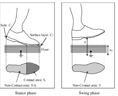
Stance phase Swing phase
Figure 1. Schematic of interaction between the human body and the floor surface layer during walking motion.
The reciprocal of capacitance of the feet relative to the ground
( )
Csf may be calculated as the sum of the reci-procal of capacitance of the sole( )
Cs and the reciprocal of capacitance of the floor surface( )
Cf , as shown below:1 1 1
sf s f
C =C +C . (1)
The electric capacitance between the sole and floor
( )
Cx can be expressed as follows:(
)
(
0)
0 0(
(
0)
0)
0 0a f a c
f c
a c
x
Sx x x x S
S
S S
C
x x x x x x
ε ε ε
ε
ε − + − −
= + =
− − . (2)
where S is the area of the sole, and Sc is the contact area between the sole and floor. Further,
(
S−Sc)
is the delamination area of the sole against the floor, and x and x0 denote the distances between the sole and the earth and the floor surface and the earth, respectively. In addition, εa is the permittivity of the air gap between the sole and the floor, and εf is the averaged permittivity of the floor materials between the floor surface and the earth. Further, S must be replaced with an area of the sole projected onto the floor. However, the projected area is ex-actly similar to S in the case of normal waking motion. Therefore, S is assumed to be a time-independent con-stant value in place of the projected area in the above equation.On the other hand, the electric capacitance of the human body (CB) during walking motion can be expressed as follows:
1 1 1
B sf x
C =C +C . (3)
Therefore, the electric potential of the human body
( )
UB during the motion of walking can be expressed as follows:(
)
(
0)
00 0 0
B B
B B
B sf a f a c
x x x
Q Q
U Q
C C ε Sx ε x x ε x S
−
= = +
+ − − . (4)
where QB is the instantaneous charge of the human body during walking motion. The induced charge
( )
Q of a measurement electrode placed at a certain distance from the subject can be expressed as(
B)
Q=C V−U . (5)
foot is lifted off the floor, Sc decreases. Therefore, I increases as predicted by the second term on the right-hand side of Equation (6). On the other hand, the first term on the right-hand side of Equation (6) represents the cur-rent induced by the motion of the foot before it is lifted off the floor. The first term is approximately proportion-al to the speed of the foot in a direction perpendicular to the floor. However, the first term of Equation (6) has a small effect on I because εa is less than εf. Additionally, the speed of motion in a direction perpendicular to the floor is less in the case of typical walking motion. Therefore, the influence of the first term of Equation (6) on signal intensity is small when compared with that of the second term of Equation (6) in the case of normal walking motion. Therefore, in the case of walking motion near the measurement electrode, the electrostatic in-duction current generated when the subject’s foot is in contact with and off the floor can be measured under perfect noncontact and nonattached conditions.
3. Experimental Method
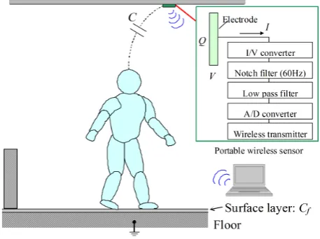
A schematic of the measurement system for the electrostatic induction current generated owing to the variation in the electric potential of a subject’s body is shown in Figure 2. The electrostatic induction current flowing through an electrode in the wireless portable sensor placed less than 5 m from the body of the subject is con-verted into voltage with an I V- converter having a conversion ratio of 20 V/pA and comprising an operational amplifier (op-amp). The I V- converter consists of two low input current op-amps, a feedback capacitance
[image:4.595.199.428.524.695.2]( )
Cf of approximately 0.2 pF, and a feedback resistance( )
Rf of 10 TΩ, as shown in Figure 3. The stray capacitance is formed by winding a tinned copper wire on the feedback resistance because the required electric capacitance is less than the minimum value of a marketed capacitor. The selected low-noise op-amp has an input offset voltage of 40 μV and an input offset current of 1 pA. The feedback resistor connected to the op-amp is a hermetically sealed large value resistor that can prevent stray current due to humidity. For measurements with high input resistance, a conventional guarding method is absolutely necessary for shielding op-amps; this pre-vents stray currents from entering sensitive nodes. Sensitive nodes are surrounded by a guard conductor that is maintained at the same electric potential as the sensitive node. In addition, induction currents generated by commercial power sources manifest in the form of noise. Therefore, a filtering system with a cutoff frequencyFigure 3. Schematic circuit diagram of I-V converter.
of 20 Hz and a 60-Hz notch filter are used. This measurement system is unaffected by noise from other elec-tronic devices such as mobile phones and microwave ovens. The analog signals are subsequently converted into digital signals with a 16-bit analog-to-digital (A/D) converter.
The XBee protocol is used for wireless data transmission from the portable motion detection system to a per-sonal computer. Data were acquired at a sampling frequency of 100 Hz, which is safe because the actual data transmission rate on XBee networks is as low as approximately 10 kbps. This sampling frequency is sufficient for detecting contact events. The measurement electrode is a square with a side of 2 cm. The wireless portable sensor was placed in the ceiling of an ordinary house with wooden floors, as shown inFigure 4. The subjects were asked to wear slippers and walk normally on the wooden floor. The subjects (A, B, and C) were 3 healthy men aged between 19 and 20 years. The subjects were asked to walk in a cycle of approximately 100 steps per minute to maintain the same cycle of walking. Moreover, the signal produced when the subject walked with the ankle and knee fastened to a splint with bandages to simulate a limp was measured. Subject A was asked to per-form different tasks such as walk normally (Case 1), walk with the left ankle fastened to a splint using bandages (Case 2), and walk with the left ankle and left knee fastened to a splint with bandages (Case 3).
4. Results and Discussion
4.1. Walking Signal
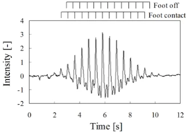
Figure 4 shows the typical waveform of the current generated during human walking motion. Cadence compo-nents are observed in the resulting waveform for each case. These compocompo-nents indicate the presence of a gait cycle in the walking motion. This gait cycle consists of a combination of alternating swing and stance phases for the left and right feet. The waveform contains cadence components for both feet during bipedal walking indi-cating that the toe of the left foot is lifted off the floor while the heel of the right foot simultaneously comes in contact with the floor. When the toe of the right foot is lifted off the floor, S decreases, and the distance between the right foot and floor
( )
x increases steadily. As a result of the walking motion, I increases, as predicted by the first term on the right-hand side of Equation (6). In rapid succession, I decreases, as predicted by the second term on the right-hand side of Equation (6). Furthermore, during the second half of the swing phase, a rapid de-crease in x induces a reduction in I, as predicted by the first term on the right-hand side of Equation (6). In rapid succession, I decreases with an increase in S owing to heel contact, as predicted by the second term on the right-hand side of Equation (6). Therefore, Equation (6) effectively explains the behavior of the waveform of the electrostatic induction current flowing through the measurement electrode.The portable sensor was placed in ceiling of an ordinary house with a wooden floor, as shown inFigure 2. The subjects were asked to wear slippers and walk normally on a wooden floor. The waveforms of the electros-tatic induction currents generated during walking motion are shown inFigure 5. The variation in the intensity of the signal obtained by the portable sensor indicates that the subject is moving closer to the portable sensor and then moving away from it. Therefore, detailed information about physical activity can be estimated using our proposed technique. We have developed an effective noncontact technique for the detection of human physical activity using human-generated body charge.
Figure 4. Typical waveform of current generated owing to human walking motion.
Figure 5. Waveforms of current generated owing to human walking motion for 40 s.
technique effectively explains the behavior of the waveform of the electrostatic induction current flowing through a given measurement electrode in a wireless portable sensor via a capacitance model for the human body.
4.2. Physically Disabled Walking
Experimental tests of physically disabled walking motion were conducted because a significant variation occurs in the time derivative of the contact area between the sole and the floor
(
dSc dt)
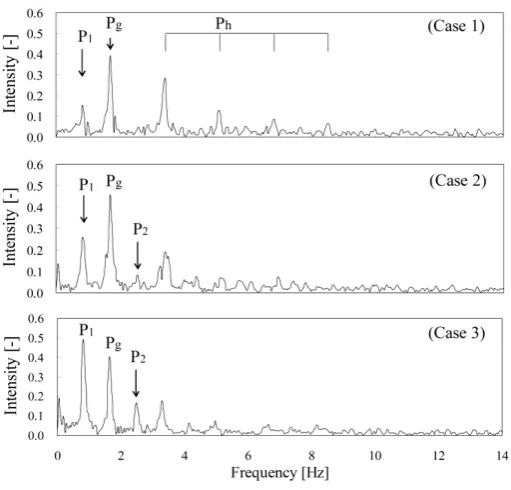
, which is represented by the second term on the right-hand side of Equation (6), in such motion.Figure 6 shows the typical waveforms of the electrostatic induction current generated in each case. In this figure, the waveform of Case 1 is obtained under normal walking condition. As can be clearly seen, peaks are induced by both feet in a period of the walking cycle. The peaks R and L represent the waveform induced by the right and left feet, respectively. The obtained waveforms are similar for each foot. The waveform of Case 2 was obtained under the walking condition where the left ankle is fastened to a splint using bandages. In Case 2, the waveforms of the left leg are slightly different from those of the right leg when compared with the normal walking motion (Case 1). Moreover, dual peaks are observed in the waveform of the right foot. Fastening of the left ankle of the subject influences not only the mo-tion of the left foot but also that of the right foot. The waveform of Case 3 was obtained under walking condimo-tion where the left ankle and left knee are fastened to a splint with bandages. The waveforms of the left foot are sig-nificantly different from those of the right foot in Case 1 and Case 2. The intensity of peaks( )
L is reduced when compared with Case 1 and Case 2. Moreover, a broadening of the peaks is observed for the right foot. Therefore, the cadence patterns of the induced current vary with fastening conditions.Figure 6.Waveforms of current generated owing to normal walking motion (Case 1 shown in upper panel), walking with the left ankle fastened to a splint using bandages (Case 2 shown in middle panel), and walking with the left ankle and left knee fastened to a splint using bandages (Case 3 shown in lower panel).
[image:7.595.185.441.410.655.2]5. Conclusion
This paper presented the development of an effective noncontact and nonattached technique for the detection of human physical activity using human-generated body charge. This technique involved the detection of an elec-trostatic induction current of the order of approximately sub-picoamperes flowing through an electrode. A theo-retical model was proposed for the electrostatic induction current generated during the walking motion. The proposed model was compared with the theoretical model and was shown to effectively explain the behavior of the waveform of the electrostatic induction current flowing through the measurement electrode. The normal walking motions of daily living were detected with a portable sensor located in a regular house. The obtained results showed that detailed information of physical activity such as a gait cycle could be estimated using our proposed technique. The electrostatic induction current was also measured when the subject walked with the left ankle and left knee fastened to a splint with bandages to simulate a limp. The obtained results show that the de-gree of fastening of the foot is directly reflected in the generated electrostatic induction current. This technique can detect even subtle differences in the walking style. Therefore, the proposed technique based on the detection of the signal generated owing to walking motion can be successfully employed to not only estimate the gait cycle and number of steps but also study the quality of walking motion.
Acknowledgements
This research was partially supported by the Grant-in-Aid for Scientific Research (C), 26350056, 2014.
References
[1] Davis, M.G. and Fox, K.R. (2007) Physical Activity Patterns Assessed by Accelerometry in Older People. European Journal of Applied Physiology, 100, 581-589. http://dx.doi.org/10.1007/s00421-006-0320-8
[2] Rikli, R.E. (2000) Reliability, Validity, and Methodological Issues in Assessing Physical Activity in Older Adults. Re-search Quarterly for Exercise Sport, 71, S89-S96.
[3] Plasqui, G. and Westerterp, K.R. (2007) Physical Activity Assessment with Accelerometers: An Evaluation against Doubly Labeled Water. Obesity, 15, 2371-2379. http://dx.doi.org/10.1038/oby.2007.281
[4] Pate, R.R., et al. (1995) Physical Activity and Public Health. A Recommendation from the Centers for Disease Control and Prevention and the American College of Sports Medicine. Journal of the American Medical Association, 273, 402-407. http://dx.doi.org/10.1001/jama.1995.03520290054029
[5] Ballor, D.L. and Keesev, R.E. (1991) A Meta-Analysis of the Factors Affecting Exercise-Induced Changes in Body Mass, Fat Mass, and Fat-Free Mass in Males and Females. International Journal of Obesity, 5, 717-726.
[6] Fogelholm, M. (2000) Effects of Walking Training on Weight Management after a Very Low Energy Diet in Preme-nopausal Obese Women: A Randomized Controlled Trial. Archives of Internal Medicine, 160, 2177-2184.
http://dx.doi.org/10.1001/archinte.160.14.2177
[7] Dunn, A.L. (1999) Comparison of Lifestyle and Structured Interventions to Increase Physical Activity and Cardiores-piratory Fitness: A Randomized Trial. Journal of the American Medical Association, 281, 327-334.
http://dx.doi.org/10.1001/jama.281.4.327
[8] Morris, J.R.W. (1973) Accelerometry—A Technique for the Measurement of Human Body Movements. Journal of Biomechanics, 6, 729-739. http://dx.doi.org/10.1016/0021-9290(73)90029-8
[9] Williamson, R. and Andrews, B.J. (2001) Detecting Absolute Human Knee Angle and Angular Velocity Using Acce-lerometers and Rate Gyroscopes. Medical Biological Engineering Computing, 39, 1-9.
http://dx.doi.org/10.1007/BF02345283
FES Assisted Walking. Medical Engineering Physics, 25, 879-885. http://dx.doi.org/10.1016/S1350-4533(03)00116-4 [11] Amoruso, V., et al. (2000) An Improved Model of Man for ESD Application. Journal of Electrostatics, 49, 225-244.
http://dx.doi.org/10.1016/S0304-3886(00)00020-6
[12] Ohsawa, A. (2001) Electrostatic Characterization of Antistatic Floors Using an Equivalent Circuit Model. Journal of Electrostatics, 51-52, 625-631. http://dx.doi.org/10.1016/S0304-3886(01)00031-6
[13] Ficker, T. (2006) Electrification of Human Body by Walking. Journal of Electrostatics, 64, 10-16. http://dx.doi.org/10.1016/j.elstat.2005.04.002
[14] Kurita, K. (2009) New Estimation Method for the Electric Potential of the Human Body under Perfect Noncontact Conditions. IEEJ Transactions on Electrical and Electronic Engineering, 4, 309-311.