Modeling and Analysis of Wireless Controller Area
Network—A Review
Gerardine Immaculate Mary1, Z. C. Alex1, Lawrence Jenkins2 1
School of Electronics Engineering, VIT University, Vellore, India 2
Department of Electrical Engineering, Indian Institute of Science, Bangalore, India Email: [email protected]
Received October 15, 2012; revised November 15, 2012; accepted December 15, 2012
Copyright © 2013 Gerardine Immaculate Mary et al. This is an open access article distributed under the Creative Commons Attribu- tion License, which permits unrestricted use, distribution, and reproduction in any medium, provided the original work is properly cited.
ABSTRACT
This paper reviews the research work done on the Modeling and Analysis of Wireless Controller Area Network (WCAN). The controller area network (CAN) has been long regarded as the pioneer in standardizing vehicle bus stan- dard. Its influence has even been reached out to various applications in industrial automation; which includes military, aviation, electronics and many others. With wireless technology becoming more pervasive, there is also a need for CAN too to migrate and evolve to its wireless counterpart [1]. A few methods were proposed in the last decade [2-6] that utilized the advantageous of CAN into a wireless network system called wireless controller area network (WCAN). This paper reviews these approaches of WCAN.
Keywords: Wireless CAN Modeling and Analysis; WTRP; RTS/CTS; WCAN
1. Introduction
The wireless controller area network (WCAN) is a new approach of using CAN message-based protocol in wire- less network. Various ideas have been proposed by re- searchers to allow ease of transition from CAN into WCAN [2-6]. Most of this research is centered on the role of the MAC layer in providing protocol to WCAN.
Dridi et al. in [2-4], propose the application of a con- tention-based WCAN protocol using the RTS/CTS me- chanism that is used in IEEE 802.11 protocol. The RTS/ CTS mechanism is used to reduce frame collisions intro- duced by the hidden node problem. Dridi et al. uses RTS/ CTS mechanism in managing priority between nodes. Changes are done to the standard RTS/CTS frame that allows for message identifier. The MAC-addresses in RTS and CTS frame are replaced by the 29-bit CAN message identifier to allow a message-based protocol. Additionally, the RTS/CTS mechanism is used to enable a station or node to reserve the medium for a specified amount of time by specifying in the duration field the amount of time that the station/node requires for a subse- quent transmission. This reservation information is stored at all stations in a variable called Network Allocation Va- riable (NAV) and represents the Virtual Carrier Sense. Inter-Frame Space (IFS) values are used to control the
priority access of the station to the wireless medium and it represents the time interval between each transmission of frames, with Short IFS (SIFS) as the smallest type of IFS [1].
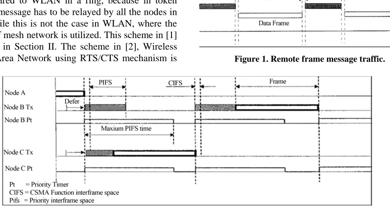
On the other hand, the WMAC (Wireless MAC) WCAN allows several nodes to communicate with each other without the assistance of a central node. The contention situation is solved by utilizing different Priority IFS (PIFS) for each message. Each node must wait for a PIFS time value before it is allowed to send its message. PIFS times provide message priority and are derived from the scheduling method which is performed by the user ap- plication. The message with the shortest PIFS takes the highest priority, as it requires the shortest delay to access the channel. Figure 2 shows how PIFS provides channel access to two nodes. In Figure 2, node B and node C try to access the channel at the same time. As node C has the shorter PIFS, it senses that the channel is idle and starts transmitting its message. After a short while, node B’s PIFS expires and it senses that the channel is currently occupied by node C. Therefore, node B waits for node C to conclude its transmission before it transmits out its message packet.
Inspired by the token frame scheme introduced in [7- 12], the authors in [1], propose WCAN using token frame in transmitting messages around the network. Also, the token defines the ring network by setting the successor and predecessor fields present in each node. Following this scheme, the WCAN presented in [1], is a wireless- based distributed medium access control (MAC) protocol for ad-hoc networks. Having a wireless based distributed MAC has the advantage of being robust against single node failure, as it can recover gracefully from it. Addi- tionally, nodes are connected in a loose and partially connected manner. The results of the analysis infer that WCAN with token scheme when compared to WLAN in ring network performs better with increased throughput, because of reduced collisions in the token scheme. The WCAN with token scheme has greater end-to-end delay when compared to WLAN in a ring, because in token scheme the message has to be relayed by all the nodes in the ring, while this is not the case in WLAN, where the advantage of mesh network is utilized. This scheme in [1] is presented in Section II. The scheme in [2], Wireless Controller Area Network using RTS/CTS mechanism is
presented in Section III. And Conclusion is presented in Section IV.
2. Wireless Controller Area Network Using
Token Frame
WCAN is the new adaptation of its wired cousin CAN. The WCAN presented in [1] utilizes some of the pro- perties available in WTRP as its protocol. WTRP is a wireless based distributed medium access control (MAC) protocol for ad-hoc network. Coincidently, these same properties are required for the success of the WCAN sys- tem. The advantages of distributed MAC are its robust- ness against single node failure and its support for flexi- ble topologies that allows a node to partially connect to the network system [7-12].
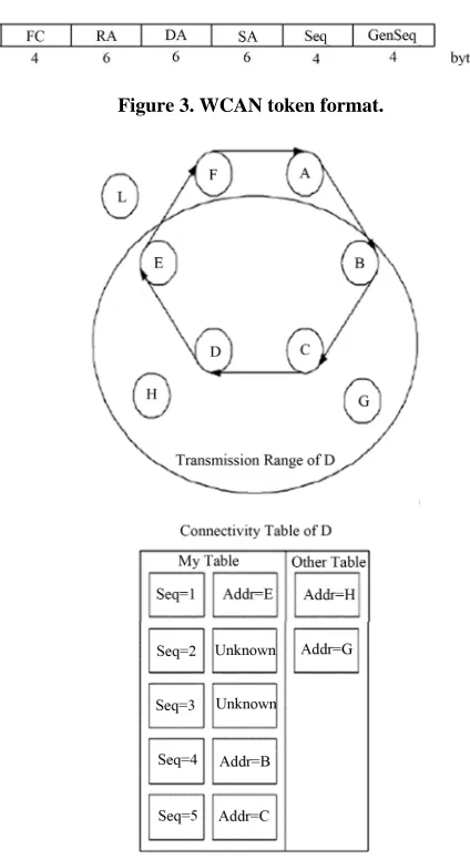
Depending on the requirements and the CAN frame format, some modifications are needed to be done on token frame. Figure 3 shows the proposed token frame used in the WCAN architecture system. Frame control (FC) contains an SOF, a 29-bit message identifier (that is used in Extended CAN), an RTR, and a reserved bit (that is to be defined in the future). In addition to these, the ring address (RA), destination address (DA), and the source address (SA) are added into the frame to define the direction of the token frame. (RA refers to the ring to which the token frame belongs). The sequence number is used to build an ordered list of stations or nodes that are present in the ring. An example of an ordered list of avai- lable nodes in a sample ring can be seen in Figure 4. Ge- neration sequence is incremented at every rotation of the token by the creator of the token.
[image:2.595.107.505.508.725.2]In Figure 4, station D monitors the successive token transmission from B to C before the token comes back to
Figure 1. Remote frame message traffic.
Figure 3. WCAN token format.
Figure 4. The ordered list and system architecture of station D.
E. At time 0, D transmits the token with sequence num- ber 0, at time 1, E transmits the token with the sequence number 1 and so on. D will not hear the transmission from F and A but when it hears the transmission from B, D will notice that the sequence number has been in- creased by 3 instead of 1, This indicates that there were two stations that it could not hear between E and B. With this information, station D could build an ordered list of nodes that are available in the ring as shown in the con- nectivity of D.
As aforementioned, the WCAN system in [1] is a hy- brid between WTRP and CAN. Therefore, in order for a station or node to win the arbitration and gain access to the medium, it must first capture the token that is circu- lating in the ring and place its message identifier into the FC field.
The token is then transmitted out to the next station in the ring based on the ordered list that the station has. The next station captures the token and examines the message
identifier first. If the message identifier has the higher priority, the station will transmit the same token to the next station on the ordered list. However, if the station wants to transmit a message or information which itself has higher priority, it will replace the message identifier in the token with its own and transmits it to the next station. A station or node will know if its transmission is successful only when the token it receives next contains the same message identifier it has. Otherwise, it will be in receiving mode until it receives the token back with a lower priority message identifier.
In order for the ring to be flexible in its network to- pology, partial connectivity has been introduced. Nodes are allowed to join the ring in a dynamic manner. Nodes can join if the rotation time (sum of token holding times per node) would not grow unacceptably with the addition of the new node. Figure 5 illustrates an example of node G joining the network. Node B invites node G to join by sending out a SOLICIT_SUCCESSOR token. Node G accepts the token and responds by sending out a SET_ SUCCESSOR token to node B. The node B will then transmit yet another token, SET_PREDECESSOR to node G indicating that node C will be the predecessor node of node G. Node G sends the SET_PREDECESSOR token to node C, and brings the joining process to completion.
[image:3.595.317.529.498.720.2]A different approach is done to enable a node to leave the network. Figure 6 illustrate how node C leaves the ring network. Firstly, node C waits for the right to trans- mit. Upon reception of the right to transmit, node C sends the SET_SUCCESSOR token to its predecessor node B with the address of its new predecessor node D. If B can hear D, B tries to connect to node D by sending a SET_PREDECESSOR token. If B cannot be connected
Figure 5. Node G joining the network.
to node D, node B will find the following connected node and send the SET_PREDECESSOR token.
2.1. WCAN Operation
The WCAN operation can be divided into two main ope- rations; namely the normal operation and the soliciting operation. The normal operation involves only data pac- ket transmission within WCAN network with a set num- ber of nodes. The soliciting operation however engages a lot of decision making, as it involves soliciting operation with nodes that are outside of the network [13,14].
In normal operation, a node makes only certain chan- ges on its operating module. In this operation, there is no joining process, which means either the ring is full or there is no station outside of the ring. When a node gets the token in its idle state, it goes to have token and mo- nitoring state. The station goes back to the idle state from the monitoring state when it receives the implicit ack.
The soliciting operation involves many procedures in order for a node to join or leave the network. In order for the ring to be flexible in its network topology, partial connectivity has been introduced. Nodes are allowed to join the ring in a dynamic manner. Nodes can join if the rotation time (sum of token holding times per node) would not grow unacceptably with the addition of the new node. A different approach is done to enable a node to leave the network. For a node to leave the network, it must first inform its successor and predecessor that it is leaving the network.
In order for a node to gain access to the medium, the node must first capture the token that circulates around the network. The token is generated first by a ring master assigned in the network. Once a token is captured, a node wins the arbitration by comparing the message identifier located in FC. Once a node wins the arbitration, it will place its message identifier into the FC field and starts transmitting its data to the next node on its list, which is the predecessor. Otherwise, the said node will be in the receiving end and relays the token until it receives a token with lower message identifier priority.
The following steps describe the process of WCAN operation. For simplicity, it is assumed that each node knows its successor and predecessor nodes during this operation [13,14].
From the initializing process, the ring owner of the network begins its operation by creating the first token to be circulated into the network. If the owner has data to transmit, it adds a data frame into the token and changes the frame type to data token frame. Other nodes in the network are shifted into idle mode till they receive the circulated token.
When another participating node receives the cir- culated token during the idle state, it checks for the
frame type of the token first before comparing the MsgID of the token. If the receiving node receives the data token, it first checks if the MsgID is dedicated to the node. If yes, it will process the received data by sending it to the node’s upper OSI layer. Otherwise, the node checks for any data to be transmitted and begins the arbitration process. For successful arbitra- tion, the node will replace the frame MsgID and re- move the data from the token.
Otherwise, the node stores its data in its buffer before getting a chance to transmit it. The process is relatively the same when the node receives an empty token, with the exception of arbitration process.
Once the node finishes the process, the node will begin transmitting an acknowledgement frame to its predecessor or previous hop node. During this time, the node goes into monitoring state and awaits the acknowledgement reply.
A source node will know if its transmission is suc- cessful only by receiving the data token that consists of the same MsgID in it. The source node in return frees the token and releases it to the ring network.
2.2. Timing
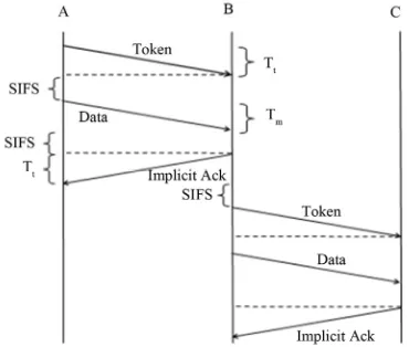
As stated earlier, the transmission of messages in WCAN proceeds in one direction along the ring network. Figure 7 shows the timing diagram of WCAN token and mes- sage. Assume that there are N nodes on the said ring network. Also, m and t are defined as the time
needed in transmitting messages, and token, respectively. Out of the total N nodes in the network, another assump- tion is that only n active nodes are actively operating while the other nodes are inactively operating [1,13,14].
T T
[image:4.595.329.514.562.719.2]By assuming the propagation delay (PROP) as DCF (Distributed Co-ordination Function) interframe space (DIFS), which is the period of time when channel is avai- lable, the token rotation time (TRT) can be calculated as [1]
m
TRT n T DIFS N
TtDIFS
S
(1)
In WCAN, the active nodes may send one packet and one token in a token rotation cycle, while the inactive nodes just forward the token. Thus, the aggregate th- roughput, for a token ring network with n active nodes may be derived as [1]
m
m t
s n T R n T N T DIFS (2)
It is proven in [1] that the use of the token concept has its advantages in terms of improving efficiency by re- ducing the number of retransmissions due to collisions, which is fairer as all stations use the channel for the same amount of time. The WCAN protocol utilizes the token frame that allow nodes to share a common broadcast channel by taking turns in transmitting upon receiving the token frame that is circulating around the network for a specified amount of time. The token frame allows nodes to access the network one at a time, giving “fair” chance to all nodes, instead of them competing with one another. Moreover, the token frame method provides high th- roughput in a bounded latency environment.
3. Wireless Controller Area Network Using
RTS/CTS Mechanism
Wireless industrial networks are data-centric, these net- works are deployed in critical applications, where the timeliness is perhaps the most difficult requirement to meet, due to the tradeoffs between power consumption, interference mitigation, scheduling and routing efficiency. Several research challenges in the networking, operat- ing systems and middleware layers must be coordinated to identify adequate solutions. Existing MAC protocols for multihop wireless networks can be classified into four categories: 1) scheduling based; 2) collision free; 3) con- tention based; and 4) hybrid schemes.
These existing MAC protocols focus more on optimiz- ing system throughput. The key challenge remains to provide predictable delay and/or prioritization guarantees while minimizing overhead packets and energy consump- tion.
In [2], the contention based protocol using the Request To Send/Clear To Send (RTS/CTS) mechanism is ap- plied with priority considerations to manage concurrency.
3.1. WCAN with Priority
WCAN with priority is an extension of the WCAN pro- tocol by the integration of algorithms to manage concur- rency [15]. WCAN is an adaptation of the CAN protocol for use in Wireless industrial communications. RTS/CTS mechanism can be adopted easily for the WCAN case [15]. However, depending on the CAN frame format, some modifications should be done. The new CAN
frames as detailed in paper [16].
In the RTS, CTS and ACK frames, the MAC-ad- dresses are replaced by the 29-bit CAN_ID, within the arbitration field.
The 2-bits ACK field within the CAN frame is re- placed by a dedicated ACK frame.
The IFS (Inter-Frame Space) access priority and bi- nary exponential back-off algorithm to gain access to the medium is still used.
The main modification of the RTS/CTS scheme in the WCAN case is that the MAC address is substituted by the Arbitration field. This characteristic means that the WCAN protocol is Data-Centric so it is based on total diffusion or directed diffusion. However, the RTS/CTS mechanism cannot be used for MPDUs with broadcast and multicast immediate address because there are mul- tiple destinations for the RTS, and thus potentially mul- tiple concurrent senders of the CTS will respond. On the other hand, the RTS/CTS mechanism need not be used for every data frame transmission, because the additional RTS and CTS frames add overhead inefficiency. The me- chanism is not always justified, especially for short data frames.
In [2], the authors propose an algorithm based on the RTS/CTS frames to:
Manage priority between data frames;
Minimise numbers of CTS in response of an RTS; Optimise Energy consumption.
RTS/CTS mechanism is used in 802.11 standards to enable a station to reserve the medium for a specified time through the use of RTS and CTS frames. In this case of WCAN this mechanism is used for medium res- ervation and essentially for priority arbitration by Ob- ject-ID.
3.2. Producer/Consumer Model
The producer (henceforth mentioned as sender) is an application that captures information and diffuses it for consumers (mentioned hereafter as receiver).
The sender senses the medium when it is in the idle state. It waits for a period of short Inter Frame Space (SIFS) and sends its RTS frame. After sending its RTS frame, the sender waits, for an extended SIFS (ESIFS), for an eventual CTS frame that indicates that there is another sender having a more priority data level.
1 0 2 Priority period i n ii n i
b n in i n i Sb
S
a Slot Time
(3)
n = posfirst 1;
i: value of the bit in the position i of the immediate
more priority Object-ID; a Slot Time.
In this step, the node must calculate the Object-ID of the immediate more priority data level. To deduct this value the sender makes a binary subtraction of his Ob- ject-ID by 1. The resulting Object-ID is used to determi- nate the n parameter used in the above formula. In this formula n is the position of first bit that the value is equal to “1”. If after ESIFS “Extended SIFS” no CTS frame was received the node concludes that his data have the most priority and send his data frame [2].
Priority periodESIFSSIFS (4)
ASlot Time: The value of the correspondingly named PHY characteristic.
In the case of receiving a CTS frame that indicates the presence of a data to transmit with more priority level, the node updates his network allocation vector (NAV) with the value of Duration/ID field in the CTS frame. To save energy, the node sleeps for the duration of NAV if it is not a consumer of the data designated by the Object-ID of the received CTS frame.
Consumers (receivers) are nodes that need the data referenced by the Object-ID. Every node that receives an RTS frame must compare its Object-ID with that in the RTS frame if it has data to transmit. If it has no data to send, it updates its NAV with the duration mentioned in the Duration/ID field of the received RTS frame. If it is not a consumer, it sleeps for the period of the NAV. In the case of having a more priority level the node senses a medium. If the medium is in the Idle state for Priority SIFS (PSIFS) it sends a CTS frame. The PSIFS duration permit as to encourage the send of the CTS frame of the data that have the most priority. In the case of receiving a CTS frame during the PSIFS what indicate that there is a more data priority level, the node must update its NAV and if it is not a data consumer it must sleep during the NAV period. If no CTS received during PSIFS the node conclude that it has the most priority to send and send its data after an SIFS [2].
1 0 2 i n i i a n PSIFS SIFSn i n
i Si n i S
S a S P (5) With: n = posfirst 1;
a Slot Time;
i
The WCAN protocol uses a dedicated frame for ac- knowledgement to indicate the state of received data
frame. In this scheme RTS/CTS to manage priority, low level priority data frame take too much time to be trans- mitted when the network is not in use. To optimise our network use acknowledgment frames are sent in this time using the standard CSMA/CA. If there are a RTS or CTS frame received that has an ESIFS greater than DIFS and the sender node has not received an ACK frame for DIFS + SIFS time, he concludes that the data was not received and proceed for retransmission.
: value of the bit in the position i.
Let be the normalized system throughput, defined as the fraction of time the channel is used to successfully transmit payload bits. To compute, let us analyse what can happen in a randomly chosen slot time. Let tr be
the probability that there is at least one transmission in the considered slot time. And let Ps
tr
P
1 1 n
tr
P
be the probability that a transmission is successful, given the probability
. So one has [2]
(6)
1 1 1 1 1 1 n tr n n n s P n P
(7)Now, one is able to express the normalized system throughput S as the ratio [2],
Payload Information in a slot time
Length of a slot time
1 1
s tr
tr s tr s s tr c
S E
E
P P E P
P P P T P P T
(8)
s
T and Tc are the average time the channel is sensed
busy because of a successful transmission or collision respectively. The E P
is the average packet length and is the duration of empty slot time.In the case of the protocol “WCAN [15,16] with prior- ity” only RTS/CTS access mechanism is used, so colli- sion can be only between two RTS frames. Every node that has data to send must wait for an ESIFS time to send his data if there are no node that has more priority data level. Based on these constraints we obtain:
RTSs
T ESIFS HE P
RTS
c
T SIFS
(9)
(10)
is defined as the limit reached by the system throughput as the offered load increases, and represents the maxi- mum load that the system can carry in stable conditions.
4. Conclusions
In this review paper, a few different models of Wireless controller area network schemes are presented, namely the WCAN with token ring scheme, WCAN using RTS/ CTS scheme and the WCAN model using the RFMAC and WMAC. The discussion of the WCAN using token scheme and WCAN using RTS/CTS scheme is presented in detail.
In the WCAN with contention based MAC protocol, the Request To Send/Clear To send (RTS/CTS) mecha- nism is applied with priority considerations to manage concurrency. In [2], the ESIFS time versus level of prior- ity of sent data is analysed. The results conclude that for higher level priority Object-ID, ESIFS time is very low, but this time grows exponentially for low level priority Object-ID. It is guaranteed that the most high priority level data gain access to the support. On the other hand, based on these values of ESIFS the global performances of this protocol decreases for a large number of low level priority data. Similarly the throughput versus the priority level of Object-ID for different number of station is ana- lysed in [2]. It is concluded that the Throughput is nearly indifferent of the number of station but it decreases ex- ponentially for low level priority Object-ID.
The WCAN with the token scheme shares the same properties as can be found in WTRP protocol with a few modification and adjustment on the token frame. Fur- thermore, the flexibility of the topologies allows nodes to join and leave the network dynamically. The developed WCAN is built on the MAC layer as a wireless based distributed MAC protocol for ad-hoc network. WCAN was deployed using QualNet simulator and achieve mixed reaction results. Simulation results show that WCAN out- perform IEEE 802.11 in terms of throughput in a ring network environment. However, in terms of average end- to-end delay, WCAN increases linearly with increasing number of nodes and is slightly higher than IEEE 802.11. This is due to the fact that every node takes turn in trans- mitting the token around the ring network causing the overall delay to increase. From the results, it’s shown that WCAN provide “fair” share for all nodes by sched- uling the transmission with token reception. Additionally, WCAN is advantageous by reducing collision probability, by distributing the resource fairly among each node.
REFERENCES
[1] W. L. Ng, C. K. Ng, B. M. Ali and N. K. Noordin, “Wireless Controller Area Network Using Token Frame Scheme,” Proceedings of 2012 Third International Con-
ference on Intelligent Systems Modelling and Simulation, Shanghai, 8-10 February 2012, pp. 695-699.
[2] S. Dridi, B. Gouissem and S. Hasnaoui, “Performance Analysis of Wireless Controller Area Network with Pri- ority Scheme,” The Sixth Annual Mediterranean Ad Hoc Networking Workshop, Corfu, 12-15 June 2007, pp. 153- 158.
[3] S. Dridi, O. Kallel and S. Hasnoui, “Performance Analy- sis of Wireless Controller Area Network,” International Journal of Computer Science and Network Security, Vol. 7, No. 1, 2007.
[4] B. BenGouissem and S. Dridi, “Data Centric Communi-cation Using the Wireless Control Area Networks,” IEEE International Conference on Industrial Technology, Mum- bai, 15-17 December 2006, pp. 1654-1658.
[5] A. Kutlu, H. Ekiz and E. T. Powner, “Performance Ana- lysis of MAC Protocols for Wireless Control Area Net- work,” Proceedings of Second International Symposium on Parallel Architectures, Algorithms, and Networks, Bei- jing, 12-14 June 1996, pp. 494-499.
doi:10.1109/ISPAN.1996.509031
[6] A. Kutlu, H. Ekiz and E. T. Powner, “Wireless Control Area Network,” IEEE Colloquium on Networking Aspects of Radio Communication Systems, Savoy Place, 11 March 1996, pp. 3/1-3/4.
[7] M. Ergen, D. Lee, R. Sengupta and P. Varaiya, “WTRP— Wireless Token Ring Protocol,” IEEE Transactions on Vehicular Technology, Vol. 53, No. 6, 2004, pp. 1863- 1881. doi:10.1109/TVT.2004.836928
[8] M. Ergen, D. Lee, R. Sengupta and P. Varaiya, “Wireless Token Ring Protocol-Performance Comparison with IEEE 802.11,” Eighth IEEE International Symposium on Com- puters and Communication, Kiris-Kemer, 30 June-3 July 2003, pp. 710-715.
[9] D. Lee, A. Puri, P. Varaiya, R. Sengupta, R. Attias and S. Tripakis, “A Wireless Token Ring Protocol for Ad Hoc Networks,” IEEE Aerospace Conference Proceedings, Vol. 3, 2002, pp. 1219-1228.
doi:10.1109/AERO.2002.1035254
[10] D. Lee, R. Attias, A. Puri, R. Sengupta, S. Tripakis and P. Varaiya, “A Wireless Token Ring Protocol for Intelligent Transportation Systems,” IEEE Intelligent Transportation Systems, 2001, pp. 1152-1157.
[11] Z. Deng, Y. Lu, C. Wang and W. Wang, “E2WTRP: An Energy-Efficient Wireless Token Ring Protocol,” IEEE 15th International Symposium on Personal, Indoor and Mobile Radio Communications, Vol. 1, 2004, pp. 574- 578.
[12] Z. Deng, Y. Lu, C. Wang and W. Wang, “EWTRP: En- hanced Wireless Token Ring Protocol for Small-Scale Wireless Ad Hoc Networks,” International Conference on Communications, Circuits and Systems, Vol. 1, 2004, pp. 398-401.
[14] W. L. Ng, C. K. Ng, B. M. Ali and N. K. Noordin, “Wireless Controller Area Network Using Token Frame Scheme in Smart Home Network,” In: Proceedings—Part III, Communications in Computer and Information Sci- ence (CCIS), Springer, Berlin, Heidelberg, 2011, pp. 544- 556.
[15] S. Hasnaoui, “RTS/CTS Access Scheme in Wireless CAN Networks,” CCCT05 Conference Proceedings, Vol. 2, 2005, pp. 254-261.