© 2018, IRJET | Impact Factor value: 7.211 | ISO 9001:2008 Certified Journal | Page 2915
EFFECT OF SOIL STRUCTURE INTERACTION ON SEISMIC RESPONSE OF
BRIDGES WITH PILE FOUNDATIONS
Aswathi M
1,
Dr. Jayalekshmi R
21
M Tech student , Department of Civil Engineering, NSS College of Engineering, Palakkad, Kerala, India
2Professor, Department Civil Engineering, NSS College of Engineering, Palakkad, Kerala, India
---***---Abstract - Civil engineering structures are elements that directly contact with ground. In early days, it is assumed that the foundation as well as the soil beneath the foundation are perfectly rigid. But neither foundation nor the soil is fixed in real case. Here comes the importance of soil structure interaction. When an external force such as earthquake act on the system structural displacement and ground displacement will be developing and are mutually dependent on each other. The process of response of soil influence the motion of the structure and vice versa is termed as soil structure interaction. Soil structure interaction have vital role in each and every construction field especially in case of high rise buildings and bridges founded on weak soil. So while designing a bridge it is very important to include the effect of SSI in design. This work is intended to study the effect of soil structure interaction on seismic response of bridges with pile foundation under Indian soil condition. It is found that as soil flexibility increases all the parameters such as bridge deck displacement, bridge deck acceleration and column shear force increases Neglecting soil structure interaction will end in the conservative result than the actual case
Keywords—Soil structure interaction, bridge pier, flexibility of soil, Winkler model etc
1.INTRODUCTION
Bridges are inevitable structures in our society which play a major role in the development of the country. Since bridges are subjected to heavy loads due to moving vehicles, its design should be done with utmost care to avoid losses of life and properties. As a common practice, load from bridge deck is transferred through longitudinal girders to the supporting pear cap and then to the piers. Piers will transfer the load to foundation. Hence all these components should be designed properly. Bridge foundation can be shallow foundation as well as deep foundation such as pile, well foundations etc.
In our country pile foundation is more common. Neglecting the effects of soil interaction may cause variation in the actual behaviour of a bridge during any external force.
2.EFFECT OF SOIL STRUCTURE INTERACTION
Soil Structure Interaction effect is important in design of engineering structures especially structures founded on soft and medium soil. In hard soil the effect is negligible.
Flexibility of soil foundation system reduces the overall stiffness of the structure and increase the natural period of the system. Considerable change in spectral acceleration with natural period is observed from the shape of the response spectrum curve. Thus the change in natural period may alter the seismic response of any structure considerably. Moreover the relationship between the periods of vibration of structure and that of supporting soil is important regarding the seismic response of the structure. The displacements increase with the increase in soil flexibility.
And also from the past works it is clear that SSI effect is more in soft soil and not relevant in hard soil. Only limited literature are available on the effect of SSI on bridges with pile foundation under Indian soil condition. And also Winkler spring model is more popular and studies are mainly concentrated on this method. So this work is attempted to study the effect of SSI on seismic response of bridges with pile foundation situated in Indian soil condition by using Winkler method. Assumptions used in this study are:
1. The effect of abutments are neglected for interior spans. 2. Piers are of equal height.
3. GEOMETRY DETAILS
The superstructure is four span simply supported RC deck slab (deck slab is discontinuous at every intermediate supports) with span length 30m. Total carriage way width is 15.6 m with four lanes of traffic. Seven number of precast concrete I section girders are used to support cast-in-place RC deck slab. The thickness of RC deck slab is assumed as 0.21m based on the details available for existing bridges. Primary elements of bridge are modeled in CSI SAP2000 version 14. Finite element meshing procedure is also assigned for the bridge superstructure.
Table 3.1 Geometric details of bridge
Geometrical details
Grade of concrete M30
Reinforcement Fe 415
Span length 30m
Total length of bridge 120 m
Width of carriage way 15.6 m
Thickness of slab 0.21m
© 2018, IRJET | Impact Factor value: 7.211 | ISO 9001:2008 Certified Journal | Page 2916 Substructure consist of RC piers with different foundation
supports. Pier height is taken as distances from bottom of a pier cap to the top of pile cap. Four cases of pier height (9m,10m,11m and 12m) and 3 cases of pier cross sections with same area of cross section were selected for the present study. Details of parameters studied is given in table 3.2 Modelling of foundation incorporating soil structure interaction can be done in two ways :
1. Winkler spring model
2. Elastic continuum model
Winkler Spring Model
In Winkler spring model the soil and the foundation is assumed as springs representing the stiffness of soil foundation system. In this type of modelling non linearity of soil foundation system is not considered.
In this study the soil-pile foundation system is modelled as Winkler springs.
Table 3.2 Details of parameters
Parameter Cross
section Length of pier Cross section dimension
Pier height Square 9m 2mx2m
Square 10m 2mx2m
Square 11m 2mx2m
Square 12m 2mx2m
Pier cross
section Circular
11m
2.25m diameter
Square 2mx2m
Rectangular 2.5mx1.6m
4. SOIL PROFILES USED IN THE STUDY
[image:2.595.300.586.98.218.2]Soft and medium soil profiles are considered for the study because in Indian condition soft and medium soil are more vulnerable than rock soil . And in this study the bridge foundation is modeled as Winkler springs. Soil properties adopted are given in table 4.1 and corresponding soil stiffness values for Winkler springs are provided in table 4.2.
Table 4.1 Soil properties
Soil
type Modulus of Elasticity (KN/m2)(E)
Poisson’s
Ratio(µ) Unit Weight (KN/m3)
Shear modulus(G) (MPa) Medium
Soil 35000 0.4 16 12.5
Soft Soil 15000 0.4 16 5.357
Table 4.2 Soil stiffness values
Soil type
Shear modulus (G)
(MPa)
KV(KN/m) KHx
(KN/m) KHz
(KN/m) KRx
(KN-m/rad)
KRz
(KN-m/rad)
Mediu
m soil 12.5 869823 614365 587389 36354800 33050200
Soft soil 5.357 518815 462033 438704 17987900 23151800
KRz is transverse stiffness (rotation)
Where,
KV is vertical stiffness (translation)
KHx is longitudinal stiffness(translation)
KHz is transverse stiffness( translation)
KRx is longitudinal stiffness (rotation)
5. SEISMIC ANALYSIS
11 ground motions are applied to the structure by response spectrum method.
Details of selected ground motion are given in table 5.1.
[image:2.595.42.560.450.780.2]© 2018, IRJET | Impact Factor value: 7.211 | ISO 9001:2008 Certified Journal | Page 2917 6. RESULTS AND DISCUSSIONS
6.1 RESULTS
Using the results obtained graphs are plotted for all the bridge design parameters such as shear force in pier, bridge deck acceleration and bridge deck displacement in both longitudinal and transverse direction.
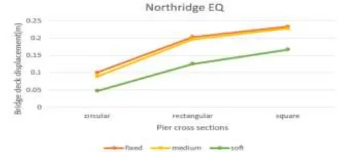
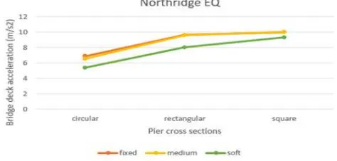
[image:3.595.312.558.90.200.2]Graphs for Northridge earthquake (since Northridge earthquake has maximum PGA) for different parameters are reported below [fig 6.1 to 6.12]
[image:3.595.40.286.234.341.2]Fig.6.1 Variation of column shear for different pier height in transverse direction
Fig.6.2 Variation of column shear for different pier height in longitudinal direction
Fig.6.3 Variation of column shear for different pier cross section in transverse direction
[image:3.595.312.555.247.360.2]Fig.6.4 Variation of column shear for different pier cross section in longitudinal direction
[image:3.595.40.290.398.505.2]Fig.6.5 Variation of bridge deck displacement for different pier height in longitudinal direction
Fig.6.6 Variation of bridge deck displacement for different pier height in transverse direction
[image:3.595.310.554.407.517.2] [image:3.595.307.554.563.674.2]© 2018, IRJET | Impact Factor value: 7.211 | ISO 9001:2008 Certified Journal | Page 2918 FIG.6.8Variation of bridge deck displacement for different
[image:4.595.47.278.84.186.2]pier cross section in transverse direction
[image:4.595.310.558.86.204.2]Fig.6.9 Variation of bridge deck acceleration for different pier height in longitudinal direction
Fig.6.10 Variation of bridge deck acceleration for different pier height in transverse direction
[image:4.595.50.273.228.329.2]Fig.6.11 Variation of bridge deck acceleration for different pier cross section in longitudinal direction
Fig.6.12 Variation of bridge deck acceleration for different pier cross section in transverse direction
6.2 DISCUSSIONS
From the graphs obtained it can be seen that for fixed base column shear force is less and increases as flexibility of soil increases in both longitudinal and transverse direction. Bridge deck displacement and bridge deck acceleration follow the same trend. That means both bridge deck displacement and acceleration increases as soil flexibility increases. Model with different pier height say 9m, 10m, 11m and 12m where analyzed for 11 ground motions in fixed base, medium soil and soft soil conditions .It is observed that as pier height increases column shear force increases for soft medium and fixed base cases. Bridge deck displacement increases as pier height increases. Similarly bridge deck acceleration also increases with the pier height.
Different pier cross-section say circular, rectangular and square type where analyzed for the same model. From this it is observed that circular cross-section has lesser column shear value where square cross section shows maximum column shear. Same trend is observed for both bridge deck displacement and bridge deck acceleration
7. CONCLUSION AND RECOMMENDATIONS
7.1 SUMMARY AND CONCLUSION
The main aim of the present study is to investigate the effect of soil structure interaction on RC bridges with pile foundation located in soft and medium soil during earthquake. To investigate this a 4 span continues bridge having span length 30m was modelled using finite element software SAP2000. Total 6 bridge configuration was selected with same span length. The set of 11 ground motions recorded on soft and medium soil where selected from PEER data base. Seismic analysis was performed for the 6 model bridges as described in previous sections.
The conclusions drawn from the study are :
[image:4.595.41.282.384.505.2] [image:4.595.43.280.564.677.2]© 2018, IRJET | Impact Factor value: 7.211 | ISO 9001:2008 Certified Journal | Page 2919 2. For all soil conditions column shear force, bridge deck
acceleration and bridge deck displacement observed to be decreasing with the decreases in pier height.
3. Circular pier cross section show lesser value for column shear force, bridge deck acceleration and bridge deck displacement in all types of soil whereas square cross section shows maximum value for the same parameters.
4. Analysis and design without considering soil structure interaction is not accurate. It means that neglecting soil structure interaction will give more conservative results than actual situation.
REFERENCES