A Session based Spatial Domain Multiple Image
Hiding Technique using Variable Bit Replacement
and Multiple Passwords
Tanmay Bhattacharya
Asst. Prof. Dept. of IT JIS College of Engineering
Kalyani, WB, India
Bikash Debnath
Asst. Prof Dept. of CSE SVIST (Baruipur) 24 Parganas (S) , WB , India
S. R. Bhadra Chaudhuri
Prof. Dept. of E&TCE BESU (Shibpur) Howrah, WB, India
ABSTRACT
For hiding secret information in images, there exists a large variety of Steganography techniques. The least significant bit (LSB) insertion method is the most common and easiest method for embedding messages in an image in spatial domain but it has some limitations such as it is easier to understand using steganalysis, this limitation has been overcame in this work. This work intends to embed multiple images in a single cover image. Three images can be embedded within a single cover image in its three different color channels (RGB) and they are embedded in between least significant bit (LSB) and moderately significant bit (MdSB). Three different passwords which are later converted into keys are used for three different color channels. Three different keys of 64 elements are generated from three different passwords. The key consists of the position values of a colored channel of the cover image where the information of a grey image is embedded using variable bit replacement (VBR) technique. Three different channels are combined to form a stego image and later grey images are retrieved from the stego image similarly. This transition of password to key and also the dependency on key imposes greater security. Another important aspect is that the same stego image bears different meaning for different receiver.
Keywords
Steganography, Session based, Multiple Keys, Variable Bit Replacement (VBR) and Moderately Significant Bit (MdSB).
1.
INTRODUCTION
Data hiding is a challenging issue. Steganography comes from the Greek words Steganós (Covered) and Graptos (Writing). Steganography in these days refers to information or a file that has been concealed inside a digital picture, video or audio file. If a person or persons view the object that the information is hidden inside, he or she will have no idea that there is any hidden information; therefore the person will not attempt to decrypt the information. The simplest steganogaphic method is carried out by embedding secret data in the least significant bit(s) (LSB) of the cover image. More complex forms are PVD, VBR, GLM etc are present.
Two main issues are considered when using the algorithm. The first issue is imperceptibility which is the visibility of the secret data to the human eyes. The second issue is capacity, i.e., how much amount of secret data that can be embedded in the cover image. In this work the main focus is to make improvement in terms of the amount of secret data and also to provide high security.
2.
STEGANOGRAPHIC TECHNIQUES
2.1 Physical Steganography
Physical Steganography has been widely used. In ancient time people wrote message on wood and then covered it with wax. Message was written on the back of postage stamps. Message was written on paper by invisible inks.
2.2 Digital Steganography
Digital Steganography is the art of invisibly hiding data within data. It conceals the fact that message exists by hiding the actual message. In this, secret data can be hidden inside the image, text, sound clip which can be represented in binary.
2.3 Printed Steganography
Digital Steganography output can be in the form of printed documents. The letter size, spacing and other characteristics of a cover text can be manipulated to carry the hidden message. A recipient who knows the technique used can recover the message and then decrypt it.
3.
REVIEW OF RELATED WORK
Different types of image steganography method exist such as LSB (least-significant-bit), PVD (pixel-value differencing), GLM (gray level modification) and VBR (variable bit replacement) have been mentioned in the following section.
3.1
Data hiding by Least Significant Bit
(LSB)
One of the most popular steganography exist is least significant bit (LSB) [1], [2] and [3] by directly replacing the LSBs of the cover-image with the message bits. Here greater amount of data can be inserted but it is easier to track it by steganalysis.
3.2
Data hiding by Pixel Value
Differencing
The pixel-value differencing (PVD) method [4] provides higher embedding capacity without introducing obvious visual artifacts. Based on PVD method, various approaches [5] have also been proposed.
Modest changes in the smooth regions can be accepted but more harsh changes in the edge regions are accepted. In the PVD based methods have been proposed to increase the embedding capacity.
neighbor. The larger the difference larger amount of secret information can be embedded.
3.3
Data hiding by Grey Level Modification
The grey level modification [6] (GLM) the information that has to be embedded is converted to binary numbers. In this technique the odd and even numbers are mapped with data within an image. It is a one-to-one mapping between the binary data (i.e. a bit stream with 1s and 0s) and the selected pixels in an image. From a given image a set of pixels are selected based on a mathematical function. The grey level values of those pixels are examined and compared with the bit stream that is to be mapped in the image.3.4
Data hiding by Variable bit replacement
In the variable bit replacement technique [8] a secret image is embedded in two steps. In the first step the secret image is changed based on the sender’s Stego-Key then its output is once again perturbed by a Transposition operator. Finally the image is embedded within the host image at two different bit positions in each byte between LSB (Least Significant Bit) and MdSB [7] (Moderately Significant Bit) by using Hash Function. At the time of extraction of secret image firstly perturbed image is extracted then by reverse engineering with the session based TO and SK the secret image is obtained
4.
THE PROPOSED SCHEME
Simple LSB method is not used as the replacement method for insertion of each bit of the secret message inside a cover image. The bit replacement actually occurs between LSB and MdSB based on key. The paper has presented a new image based steganography scheme in which multiple images can be embedded within a single cover image i.e. three images are embedded within three different channels red, green and blue respectively of a cover image. Within a single picture three new grey images are embedded and later extracted by three different session based passwords which are converted into keys. Analysis may help to detect that steganography has been implied on the cover image, but attackers cannot be able to extract the secret images from the cover image without knowing the parameters used in this process.
The entire steganographic process has two parts, one part is to insert or hide the secret images file inside a cover image, and another is to add high security feature.
4.1
Description of embedment of secret
image
At the sending end, the images are embedded in a cover image and then the stego-image is sent to the intended receivers. The insertion process is not a simple LSB method as mentioned before; it consists of a complex process and involves some calculations at various steps to insert a bit in between least significant bit (LSB) and moderately significant bit (MdSB).
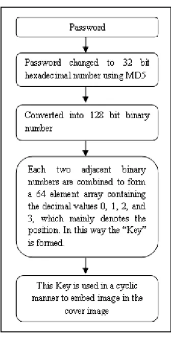
A function is included to generate a 128 bit fixed binary number from session based password, which is again reduced into a 64 elements “key” after transition (consists of decimal numbers formed by taking two consecutive binary values) and actually holds the positions, where the substitution will occur in the cover image. It consists of values within the range of 0 to 3 that means at any one of the last 4 bits (LSB to MdSB) of the given cover image according to the above mentioned 64 elements and occurs in a cyclic manner.
This conversion of password to key is actually done by using MD5 on the password which converts the key to a fixed 32 bit hexadecimal number, which is reconverted into 128 bit
binary number and then reduced to 64 elements (decimal numbers).
Three different keys are generated for three different receivers. The insertion method involves various steps where different kind of operations is done. The different steps are described in the following section of this paper.
4.1.1
The Image Embedding Method
The following diagram represents how the secret images are hidden within the cover image. The algorithm is broken into two parts.
[image:2.595.322.539.226.499.2]First part consists of how to insert the images in the cover image and the latter part comprises of how to extract the images from the newly formed stego image.
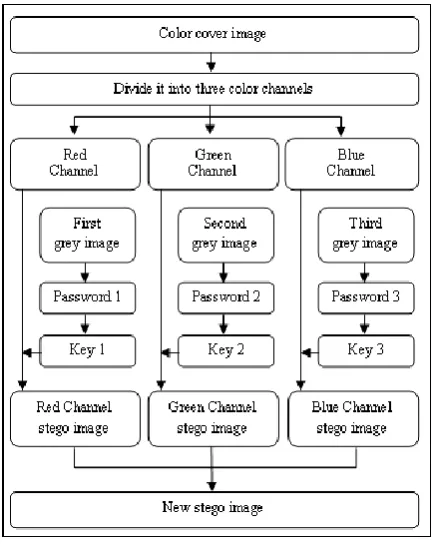
Fig 1: Part I - Algorithm for embedding of multiple images in a single cover image
The steps of the algorithm are
Step I: At the first step, a color image is taken.
Step II: The color image is broken into three color channels red, green and blue respectively.
Step III: Three passwords are taken from the sender and are converted into 128 bit number. Then each of them are paired to convert them into 64 element “Key” or array named SubArray1, SubArray2, SubArray3 respectively which mainly consists of position values, where the bits of the cover image are to be replaced for example if a sequence of binary number is there of 10 11 00 01 then new array consists of 2 3 0 1. i.e. 0 means last bit , 1 means 2nd last bit, 2 means 3rd last bit , 3 means 4th last bit respectively.
Fig 2: Conversion of a password to Key
Step IV: Three grey images are taken whose sizes are 1/3 rd of the cover image.
Step V: The grey images are converted into binary numbers.
Step VI: They are reshaped into one dimension.
Step VII: Each channel of the cover image is substituted by a new grey image with the help of the SubArray1, SubArray2 and SubArray3 in a cyclic manner as stated before. Bitset method is used.
Step VII: Each of the channels are combined to form a “stego” image
4.1.2 Explanation of the proposed scheme with
example
1. Say one of the password: “ira”
2. MD5 algorithm used on the above password to obtain the following hexadecimal number.
Columns: 1 to 16
3 c 6 7 0 8 0 a 1 a 0 9 b 0 2 2 Columns :17 to 32
[image:3.595.84.252.73.404.2]f b 9 d 9 4 e 5 7 a 7 5 d d a d Fig 3. Hexadecimal representation
(1 D Array of 32 elements) using MD5
3. Then converted to binary format Columns :1 to 16
0 0 1 1 1 1 0 0 0 1 1 0 0 1 1 1 Columns :17 to 32
0 0 0 0 1 0 0 0 0 0 0 0 1 0 1 0 Columns :33 to 48
0 0 0 1 1 0 1 0 0 0 0 0 1 0 0 1 Columns :49 to 64
1 0 1 1 0 0 0 0 0 0 1 0 0 0 1 0 Columns :65 to 80
1 1 1 1 1 0 1 1 1 0 0 1 1 1 0 1 Columns :81 to 96
1 0 0 1 0 1 0 0 1 1 1 0 0 1 0 1 Columns :97 to 112
0 1 1 1 1 0 1 0 0 1 1 1 0 1 0 1 Columns :113 to 128
1 1 0 1 1 1 0 1 1 0 1 0 1 1 0 1
4. Two consecutive bits are taken to form 64 elements i.e actually the “Key” which shows the positions.
Columns :1 to 16
0 3 3 0 1 2 1 3 0 0 2 0 0 0 2 2 Columns :17 to 32
0 1 2 2 0 0 2 1 2 3 0 0 0 2 0 2 Columns :33 to 48
3 3 2 3 2 1 3 1 2 1 1 0 3 2 1 1 Columns :49 to 64
1 3 2 2 1 3 1 1 3 1 3 1 2 2 3 1
[image:3.595.310.548.87.295.2]Fig 5.Converted into a 64 decimal numbers (2 bits / block)
Table 1. An arbitrary example to show how the proposed scheme works for a single channel of the color image
1st three position referring
to Fig 5
Grey Image 1st three
Bit value
Red Component of the image
Before embedding After embedding
Decimal value
Binary value
Binary value
New Decimal Value
0 1 148 1001
0100
1001 0101
149
3 0 149 1001
0101
1001 0101
149
3 1 152 1001
1000
1001 1000
152
5. Similarly this will occur for other two channels also, using Separate password.
[image:3.595.309.552.356.474.2]6. Then they are combined to form the stego image as mentioned in the Fig.1
[image:3.595.310.563.557.694.2]4.2
Description of extraction of secret
images
At the receiving end, the images which are embedded in the cover image to form the stego-image are extracted. The extraction process is almost similar to that of the embedding method just in reverse order. Since the inserted pictures are meant for three different receivers therefore they have three different keys and they are also converted similarly by the function as mentioned in the embedment section. The different steps are described in the following section of this paper.
4.2.1 The message extraction method
This is the second part of the method which is used to extract the images from the “stego” image. The following diagram represented the extraction of hidden images from the Stego image.
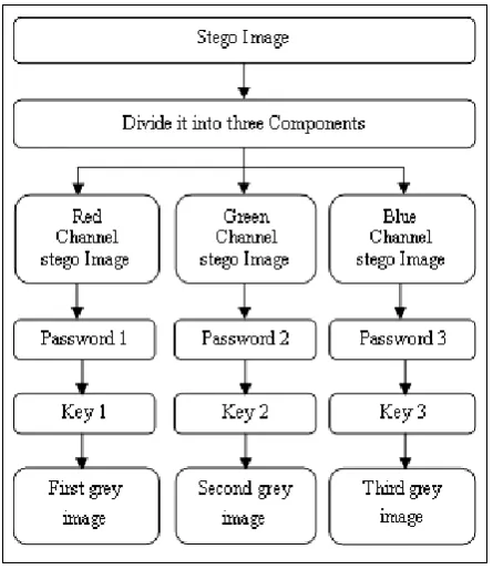
Fig 6: Part II - Algorithm for multiple images extraction from the stego image
The steps of the algorithm are
Step I: At the first step, the “Stego” image is taken.
Step II: The image is divided into three color channels red, green and blue.
Step III: Three passwords are taken from the different receivers and each of them is converted into their corresponding key as mentioned before in Fig 2, they are actually in the form of array which are SubArray1, SubArray2 and SubArray3 respectively.
Step IV: These keys are used for extraction of images from the “Stego” image. Bitget method is used.
Step V: The SubArray1, SubArray2 and SubArray3 are used respectively to extract back the images from the stego image.
Step VI: Three images are extracted.
5.
RESULTS AND DISCUSSIONS
Test 1. Calculations of PSNR and SNR
These three grey images are embedded into the following images of Fig 8. and later extracted from the stego image.
[image:4.595.317.551.138.220.2]morgan.bmp pumpkin.bmp car.bmp
Fig. 7 The three images which are to be inserted
Passwords taken are “ira”, “bikash” and “swarnali” respectively for embedding or retrieving the three different images shown in Fig 7.
The different set of cover images along with their stego images are shown below.
1
[image:4.595.58.281.266.524.2]Original: Myflower.bmp Stego: new_Myflower.bmp
Fig. 8 First set of image
2
Original: changu.bmp Stego: new_changu.bmp
Fig. 9 Second set of image
3
Original: flower.bmp Stego: new_flower.bmp
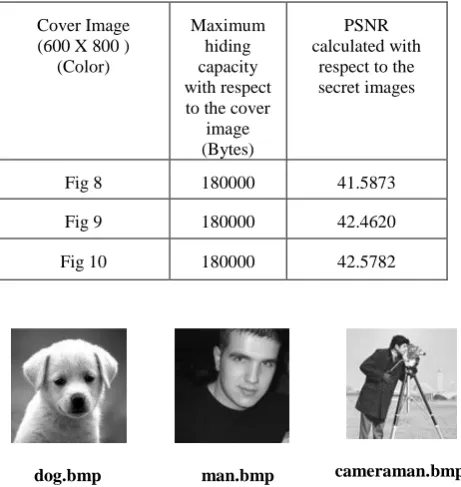
[image:4.595.312.563.321.691.2]dog.bmp man.bmp cameraman.bmp
Fig. 11 These three images are inserted in Lena, Baboon and Boat and following result is obtained which is compared with Wu-Hwang’s PVD LSB method.
Table 3. The comparison with Wu-Hwang’s PVD LSB method. Passwords used are ‘ira’, ‘bikash’ and ‘swarnali’ and images used are shown in Fig 11 of dimension 102 X 102.
Cover image (Grey)
Wu-Hwang’s PVD LSB Method
Cover image (Color)
Proposed Method
512 X 512
Capacity (Bytes)
PSNR (db)
512 X 512
Total Capacity
w.r.t. cover image (Bytes)
PSNR w.r.t.
the above images
(db)
Lena 66064 38.80 Lena 98304 42.51
Baboon 68007 33.33 Baboon 98304 42.49
Boat 66622 35.01 Boat 98304 42.57
The result obtained is better than Wu – Hwang’s PVD-LSB from the PSNR perspective. And also in Wu-Hwang’s method single grey image is inserted in a grey cover image whereas in the proposed method three grey images are inserted within a color image and also having a greater security.
6.
CONCLUSIONS
The proposed approach of hiding multiple images in a single color image is based on multiple session based passwords. So it is very difficult to find out the hidden images from the stego image if the passwords and their conversion mechanism are not known, hence high level of security is achieved. The same stego image can also bear different secret image for different receiver depending on their secret passwords. PSNR obtained is approximately 42 which confirm imperceptibility of the host and the stego image.
In future the proposed method can be extended with more efficient methods to increase the hiding capacity and also the secret images will not be affected when noise will be inserted in the stego image.
7.
REFERENCES
[1] R. Chandramouli, Nasir Memon: “Analysis of LSB Based Image Steganography Techniques”, Proc. IEEE ICIP, pp1019-1022, 2001.
[2] Dr. H. B. Kekre, Archana Athawale, Ms. Pallavi.N.Halarnkar: “Increased Capacity of Information Hiding in LSB’s Method for Text and Image”, International Journal of Electrical and Electronics Engineering 2:4 pp.246-249, 2008
[3] Yang C and Wang S: “Transforming LSB Substitution for Image-based Steganography in Matching Algorithms”, Journal of Information Science and Engineering 26, pp. 1199-1212, 2010.
[4] D. C. Wu and W. H. Tsai: “A steganographic method for images by pixel-value differencing," Pattern Recognition Letters, vol. 24, no. 9-10,pp. 1613-1626, 2003.
[5] H.C. Wu, N.I. Wu, C.S. Hwang: “Image steganographic scheme based on pixel-value differencing and LSB replacement methods”, IEEE Proceedings: Vision, Image and Signal Processing, Vol.152, Issue 5, pp.611-615, Oct 2005
[6] V. Potdar, & Chang, E., 2004: “Grey Level Modification Steganography for Secret Communication”, Proceedings of IEEE Conference on Industrial Informatics, pp. 223-228, June 2004 Berlin.
[7] Tanmay Bhattacharya, Sandeep Bhowmik & S. R. Bhadra Chaudhuri: “A Steganographic Approach by using Session Based Stego-Key, Genetic Algorithm and Variable Bit Replacement Technique”, International Conference on Computer and Electrical Engineering, pp-51-55, 2008.
[8] Ran-Zan Wang, Chi-Fang Lin and Ja-Chen Lin: “Hiding data in images by optimal moderately significant-bit replacement” Electronics Letters 7th December 2000 Vol. 36 No. 25, pp. 2069-2070.
The PSNR and Hiding Capacity values are calculated between original and stego images of the above set of pictures are given below
Table 2. The results obtained from Test 1 taking colored cover images of 600 X 800 as shown in Fig. 8, Fig.9 and Fig.10 and 3 different secret images of size 160 X 120 shown in Fig 7 are taken
Cover Image (600 X 800 )
(Color)
Maximum hiding capacity with respect to the cover
image (Bytes)
PSNR calculated with
respect to the secret images
Fig 8 180000 41.5873
Fig 9 180000 42.4620
[image:5.595.50.281.182.426.2]