© 2017, IRJET | Impact Factor value: 5.181 | ISO 9001:2008 Certified Journal | Page 617
Design of Robotic Arm based on Hand Gesture Control System using
Wireless Sensor Networks
R.Raja Prabhu
1, R.Sreevidya
21
Assistant Professor, Dept of Electrical and Electronics Engineering, Imayam College of Engineering, Trichy,
Tamilnadu, India, [email protected]
2
Assistant Professor, Dept of Electrical and Electronics Engineering, TRP Engineering College, Trichy,
Tamilnadu, India, [email protected]
---***---Abstract -
In many industries wireless operations arenecessary especially in dangerous or hazards areas. In some of the industries it is necessary to handle few jobs with very high temperature which is not possible by human hand in such cases wireless operations are more efficient. This paper focuses on design of hand gesture controlled robotic arm using microcontroller with the help of X-bee and wireless sensor networks. Simulations are being carried out and the hardware prototype was successfully implemented with the above requirements.
Key Words: Robotic manipulator, hand gesture controlled
arm,flex sensor, X-bee, Accelerometer.
1. INTRODUCTION
In today’s life automation plays very important role. Robotic arm is called as robot manipulator which can perform various functions as human arm performs. Many industries use a robot for various functions where important part of any robot is Robotic arm or called as robot manipulator should be controlled precisely depending upon application. In industry or any application robot manipulator can be used for applications like welding, trimming; picking etc. advantage of such robotic arm is it can work in hazards area, which cannot be accessed by human. Many parameters of robot are designed according to requirement. There are different ways to control robotic arm like Voice Controlled, Keypad Control, Gesture Control, etc. Implemented system consists of transmitter & receiver. Transmitter is nothing but human hand with flex sensors & receiver is robot manipulator. Motion of transmitter is wirelessly transmitted to receiver through X-bee module. Robotic arm which is receiver is nothing but a mechanical system formed by different joints and end and effectors i.e. gripper movements of these fingers or gripper can be carried out using stepper motor or servo motor when user carry out motion of hand for any application at transmitter side same movement is copied by receiver as on transmitter there are flex sensors mounted on glove at transmitter which change its resistance depending on movement of user.
2. RELATED WORK
There has been many research works in the field of Hand Gesture based Human Computer Interaction following different algorithms to develop a fast and reliable procedure for gesture recognition. In Paper [1] – [6] by Francisco Arce, Jose Mario Garcia Valdez a three axis accelerometer has been used to read different types of Hand gestures. In Paper [7] – [11] by AnalaPandit, DhairyaDand, Sisil Mehta, ShashankSabesan, AnkitDaftery used a combination of accelerometer and gyroscope and the reading are taken in to for analyzing the gesture. Here accelerometer is dedicated for collecting translational dynamic and static change in positional vector of hand and infer it to the movement of mouse whereas gyroscope has been used for rotation of virtual object. There are many papers where gestures are being analyzed using colour gloves [12] – [15]. A data glove is a type of glove that contains fiber optics sensor or flex sensors embedded in it to recognize the finger movements. Hand gesture recognition using image processing algorithms many times involve use of colour gloves. By tracking this colour glove different hand gestures can be interpreted as described by Luigi Lamberti1 and Francesco Camastra in their paper [16] – [18]. Here they have modelled a colour classifier performed by learning vector Quantization. In Paper [19] by J.S. Kim, C.S. Lee, K.J. Song, B. Min, Z. Bien, a pattern recognizing algorithm has been used to study the features of hand. There are many Papers where training of hands using a large database of near about 5000-10000 positive and negative images are considered. But this procedure is very tiring and time taking.
© 2017, IRJET | Impact Factor value: 5.181 | ISO 9001:2008 Certified Journal | Page 618 However, the invariants they considered inspired us for our
defined invariants.
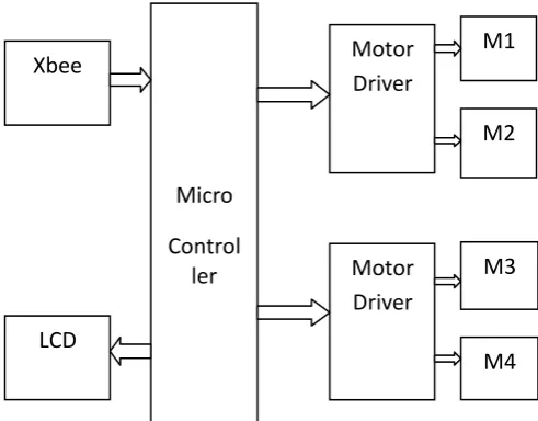
3. BLOCK DIAGRAM
The block diagram was shown in Fig.1 below. It consists of two parts which are interconnected by the wireless sensor communication systems. The X-bee will be acting as the transmitter and the receiver device system. The first part consists of gloves which were occupied by Li-ion battery, microcontroller and flex sensors. The second part consists of motor, microcontroller and robotic fingers through which the mechanical action takes place.
Fig -1: Functional Modeling analysis of the entire system
3.1 Transmitter
The below fig.2 is block diagram of transmitter consist of Microcontroller with two inputs from flex sensor & accelerometer.
Fig -2: Block Diagram of Transmitter
As shown in fig, Flex sensors are analog resistors. It works as variable analog voltage divider. Internally it consists of carbon resistive element with thin substrate. As substrate is flexible when it is bent, sensor produces resistive output which is equivalent to bend radius. The flex sensor provides greater accuracy for small movements also. Smaller the radius higher will be the resistance value. These flex sensors are mounted on human palm as user moves palm for particular applications flex sensor also bends by same amount as they are flexible. The changes due to tilt of accelerometer are in forward, backward i.e. X-axis, left, right i.e. Y-axis and up, down i.e. Z-axis. Accelerometer converts deflection into proportionate voltage & Analog to Digital converter convert analog signal into proportionate digital value. So according to positive & negative deflections motor either rotates in clockwise or in anticlockwise direction.
3.2 Receiver
The below fig.3 is block diagram of receiver, in the transmitter side x-bee transmit the signal and this signal is received by the receiver X-bee and then fed to the microcontroller which drives motor through motor driver to control movement of robot manipulator. The sensor glove reads values from the flex sensors and correspondingly sends them wirelessly using X-bee protocol to the robotic hand. The operation is overseen and controlled with the help of Atmega16 development board.
Fig -3: Block Diagram of Receiver
The sub module section with energy flow shown in Figure, gives a depiction of the operation within the sensor glove and with other peripheral components.
Xbee
Micro
Control
ler
Motor
Driver
Motor
Driver
LCD
M1
M2
M3
M4
Micro
Controller
Flex
Sensor
Xbee
[image:2.595.40.283.245.424.2] [image:2.595.318.564.431.623.2] [image:2.595.47.274.529.723.2]© 2017, IRJET | Impact Factor value: 5.181 | ISO 9001:2008 Certified Journal | Page 619
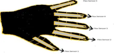
Fig -4: Flex Sensor
As shown in fig.4, flex sensors are mounted on each joint of all five fingers and bending of sensor due to hand movement of the operator changes the resistance of the sensor and this change in resistance is fed as input to the robotic unit.
Fig -5: Robotic Hand Unit
The battery’s chemical energy is converted into electrical energy and transmitted to the controller board. The board then coordinates the necessary actions by reading values from flex sensors or sending data wirelessly to robotic hand in Fig.5.
Fig -6: BO Motor
BO motor shown in fig.6 is used to move robot manipulator gripper in forward & backward direction.BO motor is brushless electric motor that divides rotation into equivalent number of steps. The position of motor can be controlled through these steps. It can hold one of these steps without any feedback sensor. If DC voltage is applied to the terminals of motor, it rotates contentiously. It accepts DC voltage as input & converts it into train of pulses i.e. square wave. Each pulse defines increment in shaft position, thus each pulse rotates shaft through a fixed angle.
4. SIMULATION DIAGRAM WITH RESULT
Below window in fig.7 shows simulation diagram with result in proteus. X-Bees are hugely popular wireless transceivers for a number of reasons. They are flexible – they send and receive data over a serial port, which means they’re compatible with both computers and microcontrollers initially we connect the xbee module to the A-B cable and
andusb port connected to computer and installing usb driver silicon labs cp210x. After installation we find silicon labs cp210x USB to UART bridge “COM28”. Now we installed software XCTU and after opening XCTU we need to set communication parameters as shown in the figure9. Baud rate = 9600, Flow control = None, Data bits = 8, Parity = None, Stop Bits = 1. Now clicking on test/query, we get model’s firmware version=10EC, Model type XB24, Serial Number= 13A20040B2EB5A. This shows testing of xbee module completed successfully. Similarly we checked second X-bee module. To test communication between your X-Bee’s we need to connect second X-Bee to a computer as well. That means doing the “Add device” one more time.
Fig -7: Simulation Diagram with Result
4.1 Configuring Networks
[image:3.595.72.253.99.193.2] [image:3.595.313.554.256.448.2] [image:3.595.69.259.276.367.2]© 2017, IRJET | Impact Factor value: 5.181 | ISO 9001:2008 Certified Journal | Page 620
Fig -8: X-bee Software GUI with Module Testing Circuit
The next level of an X-Bee network is the personal area network ID (PAN ID). The network ID is some hexadecimal value between 0 and 0xFFFF. X-Bees can only communicate with each other if they have the same network ID. There being 65536 possible ID’s, there’s a very small chance that your neighbor will be operating on the same network. Finally there are MY and destination addresses. Each X-Bee in a network should be assigned a 16-bit address (again between 0 and 0xFFFF), which is referred to as MY address, or the “source” address. Another setting, the destination address, determines which source address an X-Bee can send data to. For one X-Bee to be able to send data to another, itmust have the same destination address as the other X-Bee’s source. Overall system performance is check wirelessly by using two different power supplies for transmitter and receiver. System is working properly. Signal reception time is almost negligible.
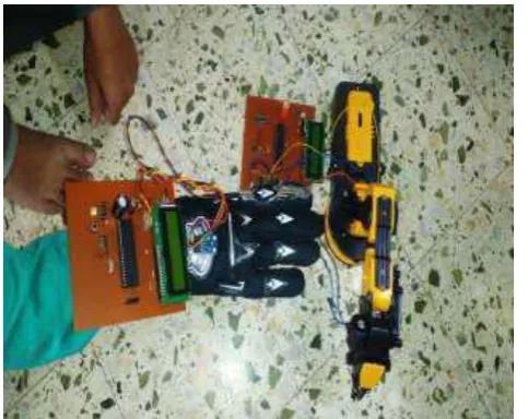
5. EXPERIMENTAL SETUP
Following fig.9 shows experimental setup which consists of transmitter i.e. glove mounted on human palm with flex sensors & receiver which is robot manipulator arm. This setup shows receiver is following movement of transmitter.
Fig -9: Experimental Setup
CONCLUSION
Gesture based interfaces allow human computer interaction to be in a natural as well as intuitive manner. This paper discussed hardware and software co-design of robotic arm controller using DC motors employing microcontroller ATMEGA16.The robotic hand has been designed to meet all of the original specifications of the project. The fingers are allowing for full motion of the hand. Observations show that the project produces the required motion of the fingers. Such type of hand gesture controlled robotic arm is mostly useful for Industrial, Medical & Military applications. This type of the hand gesture technology can be used where the humans are unable to sustain in the difficult or harsh environments. This might reduce some of the labor that is used in industry and also the life risk factor.
REFERENCES
[1] F. Arce, J. M. G. Valdez,” Accelerometer-Based Hand Gesture Recognition Using Artificial Neural Networks” in Soft Computing for Intelligent Control and Mobile Robotics Studies in Computational Intelligence, vol. 318, pp 67-77, 2011
[2] A. Pandit , D. Dand , S. Mehta , S. Sabesan , A. Daftery,” A Simple Wearable Hand Gesture Recognition Device using iMEMS,” International Conference of Soft Computing and Pattern Recognition , pp 592-597,2009
[3] R. Wang, J. Popovic, ”Real-time hand-tracking with a color glove,” ACM Transactions on Graphics, vol. 28 , pp 461-482, 2009
[4] “Luigi Lamberti1 and Francesco Camastra”, Real-Time Hand Gesture Recognition using a Color Glove,” Depart ment of AppliedScience, University of Naples Parthenope, 2010, pp.321-344
[5] J.S. Kim, C.S. Lee, K.J. Song, B. Min, Z. Bien, “Real -time hand gesture recognition for avatar motion control,” Proceedings of HCI'97, pp. 96-101,February 1997
[6] I.-K. Park, l -H. Kim, and K.-S. Hong, "An Implementation of an FPGA-Based Embedded Gesture Recognizer Using a Data Glove," Conference on Ubiquitous Information Management and Communication Proceedings of the 2nd International conference on Ubiquitous information management and communication 2008, Suwon, Korea,January31 – February 01, 2008, pp.496-500
[7] Dr. Shantanu K. Dixit and Mr. Nitin S. Shingi “Impl ementation of Flex sensor and electronic compass for hand gesture based wireless automation of material handling robot” Int ernational Journal of Scientific and Research Publications, December 2012
[8] W.T. Freeman, C.D. Weissman, Television control by hand gesture, Proceedings of the International Workshop on Automatic Face-and Gesture-Recognition, Zurich, Switzerland, June 1995, pp. 179-183.
[image:4.595.45.280.92.242.2] [image:4.595.43.285.553.745.2]Sh-© 2017, IRJET | Impact Factor value: 5.181 | ISO 9001:2008 Certified Journal | Page 621 Hussain.Salleh, Siew Kean Seng, and Leong SengHuat “Data
Gloves Malay Si gn Language Recognition System” 1- 4244-0983-7/07/$2 5.00 ©2007 IEEE.
[10] T. Starner, A. Pentland,"Visual recognition of American sign language using hidden Markov model", Proceedings of the International Workshop on Automatic Face-and Gesture-Recognition, Zurich, Switzerland, June 1995, pp. 189-194.
[11] Martin Urban, Peter Bajcsy, Rob Kooper and Jean-Chistophe “Recognition of Arm Gestures Using Multiple ori entation Sensors.” Lementec2004 IEEE Intelligent Transportation Systems conference Washington, D.C., USA, October34,2004
[12] J. Yang, Y. Xu, C.S. Chen,"Human action learning via hidden markov model", IEEE Trans. Systems, Man, Cybernet. 27 (1), 1997, pp. 34-44.
[13] Jiayang Liu, Zhen Wang, and Lin Zhong, Jehanickramasuriya and VenuVasudevan “Accelerometer-based Perso nalized Gesture Recognition and Its Applications,” 978-1-4244-3304-9 /09/$25.00 ©2009 IEEE
[14] Syed Atif Mehdi, YasirNiaz Khan, “Sign Language Reco gnition Using Sensor Gloves” Proceedings of the 9th International Conference on Neural Information Processing (ICONIP‘02), Vol.
[15] T.S. Huang, A. Pentland,"Hand gesture modeling, analysis, and synthesis", Proceedings of the International Workshop on Automatic Face-and Gesture-Recognition, Zurich, Switzerland, June 1995, pp. 73-79.
[16] PIC18F2410/2510/4410/4510 Rev. B3 Silicon Errata28/40/44-Pin Flash Microcontrollers with 10-Bit A/D and nano WattTechnology
[17] PujanZiaie, Thomas Muller and Alois Knoll,” A Novel Approach to Hand-Gesture recognition in a Human-Robot Dialog System” Robotics and Embedded Systems Group Department of 3/08 Informatics Technische University Muinchen 978-1-4244-3322- IEEE
[18] Ben W. Miners, Student Member, IEEE, Otman A. Basir,Member, IEEE, and Mohamed S. Kamel, Senior Member,IEEE “Understanding Hand Gestures Using Approximate Grap h Matching,” IEEE TRANSACTIONS ON SYSTEMS,MAN, AND CYBERNETICS—PART A: SYSTEMS ANDHUMANS, VOL. 35, NO. 2, M ARCH 2005 239
[19] Jakub Segan,"Controlling computer with gloveless gesture" In Virtual Reality System’93, 1993, pp. 2-6.
[20] E. Hunter, J. Schlenzig, R. Jain,"Posture estimation in reduced-model gesture input systems, Proceedings of the International Workshop on Automatic Face-and Gesture- Recognition, June 1995, pp. 290-295.
[21] M.J. Swain, D.H. Ballard,"Color indexing" International Journal of Computer Vision 7 (1), 1991, pp. 11-32.
[22] Sergio Rodriguez1, Artzai Picon2 and Aritz Villodas3 “Robust Vision-Based Hand Tracking Using Single Came ra forUbiquitous 3D Gesture Interaction” IEEE Symposium o n
3D User Interfaces 2010 20-21 March, Waltham, Massachusetts, USA, 2010 IEEE.
BIOGRAPHIES
R.Raja Prabhu received the B.Eng (I) in Electrical and Electronics Engineering from Anna University, Chennai in 2005. He completed the M.Eng (I) in Applied Electronics from Anna University, Coimbatore in the year 2009. He is now working as assistant professor in the department of electrical and electronics engineering in Imayam College of Engineering, Trichy, India.
His area of interest includes power electronic converters, power factor correction, energy conversion and renewable energy applications.
R.Sreevidya was born in the state of tamilnadu, India. She received the BE degree in Electrical and Electronics Engineering from Anna University, Chennai in 2010 and ME degree in Power Electronics and Drives from Anna university, Chennai in 2014. She is now working as assistant professor in the department of electrical and electronics engineering in TRP Engineering College, Trichy, India.