International Research Journal of Engineering and Technology (IRJET)
e-ISSN: 2395-0056Volume: 04 Issue: 08 | Aug -2017
www.irjet.net p-ISSN: 2395-0072© 2017, IRJET | Impact Factor value: 5.181 | ISO 9001:2008 Certified Journal
| Page 2139
CLOSED LOOP POWER CONTROL OF GRID CONNECTED DG UNITS FOR
REDUCING ACTIVE HARMONICS USING CURRENT CONTROL SCHEME
Mr.SK.KHADARBASHA
1, Mr. K.VENKATA RAVINDRA
2, Mr. T.RAVI KUMAR
31
Pg Scholar, M.Tech, Power Electronics, Geethanjali Institute Of Science And Technology, Nellore-524137,
Ap, India
2
Assistant.Prof, M.Tech, Geethanjali Institute Of Science And Technology, Nellore-524137,Ap,India,
3
Assoc.Prof,M.Tech,(Phd), Geethanjali Institute Of Scienceand Technology, Nellore-524137,
Ap, India,
---****---Abstract:
With an increase in non linear loads may raisepower quality issues at the distribution side. In order to utilize distribution generation units in effective manner we have to reduce active harmonics. In this proposed method we used current control approach, which unlined integrated DG units in order to reduce harmonics by primary DG function. In this proposed current controller consists of two decouple control branches harmonic DG currents, load harmonic current detection, system harmonic voltage detection are not required. In this closed loop control is used is used to reduce difficulty it is directly fundamental current reference without phase locked loop(PLL) .This proposed control effectively reduces fundamental current in DG units. In this project we can know how we can reduce harmonic currents due to frequency deviation using current control technique to a DG unit connected with closed loop control simulation done in Matlab/Simulink.
Index Terms:
Active power filter, distributed generation,resonant controller harmonic compensation, virtual impedance, Harmonic extraction, phase-locked loop (PLL).
I. INTRODUCTION
Now-a-days importance of renewable resources power generation is increasing; a large number of power electronic converters are used with DG units with low voltage power distribution systems. With the increase of non-linear loads like variable speed drives, LED (Light Emitting Diode) lamps will further decrease in power quality.
To reduce the harmonic distortion numbers of active and passive filters are used, By using filters cost will increases. Otherwise we use flexible control of grid connected DG units. Are reliable, where ancillary harmonic Compensation capability is integrated with primary power of DG units through control references.It is more important that DG unit’s real and reactive power will not change in harmonic compensation.
It has to satisfy fundamental DG current with power reference. This current reference is taken from ripple free voltage with fixed magnitude and PLL used to synchronise fundamental current reference with main
grid. It can also be obtained from power-current transformation.
To make easier operation with DG units with ancillary harmonic compensation capability maintaining accurate power control. This proposed current control have two parallel branches First control branch is used to control fundamental current, second branch is to control load harmonic current or feeder resonance voltage. As in pi regulation in the outer power control loop, proposed DG unit also achieves zero steady state power tracking errors even fundamental current has some steady state errors. This result shows effectiveness of DG unit at the distribution side.
II. DG UNITS WITH HARMONIC COMPENSATION
In this we briefly know about how active filters acts in reducing harmonic distortion in DG units.After we can know about proposed control strategy.
A. Conventional Harmonic Current Compensation
In this interfacing converter is connected to distribution system with a coupling of choke (Lf and Rf), load at Poc.To improve power quality of grid current (I2), The harmonic load current (I local) will be absorbed through DG current (I1) regulation. As mentioned in above that current reference consists of two parts. One is current reference. (Iref) is synchronised with Poc voltage (VPoc) as
International Research Journal of Engineering and Technology (IRJET)
e-ISSN: 2395-0056Volume: 04 Issue: 08 | Aug -2017
www.irjet.net p-ISSN: 2395-0072© 2017, IRJET | Impact Factor value: 5.181 | ISO 9001:2008 Certified Journal
| Page 2140
Fig-1.DG unit with local load harmonic current compensation capability.
Where ωD1 is the cut-off bandwidth of SOGI and ωf is the fundamental angular frequency.
The relationships between the power reference and the fundamental reference current in a single-phase DG system can be formed in the artificial stationary α − β reference frame as given below:
Where Irefα f and Irefβ f are the DG fundamental current reference and its orthogonal component in the artificial α−β reference frame.Similarly, VPoCα f and VPoCβ f are PoC fundamental voltage and its orthogonal component, respectively.
The instantaneous fundamental current reference (Iref f) of a single-phase DG unit, DG harmonic current reference (Iref h) can be obtained as
Where GD (s) is the transfer function of the harmonic extractor
With the derived fundamental and harmonic current references, the DG current reference is written as
Iref = Iref f + Iref h
Here V*P is the reference voltage for pulse width modulation (PWM) processing, Kp the proportional gain of the current controller Gcur (s),Kih the resonant controller gain at the order h, ωc the cut-off frequency of the resonant controller, and ωh is the angular frequency at fundamental and selected harmonic frequencies.
B. Conventional Feeder Resonance Voltage Compensation
DG unit should not actively regulate the PoC voltage quality in this mode. As a result of this, PoC voltage can be distorted particularly when it is connected to the main grid through a long underground cable with nontrivial parasitic capacitance. The resonance issue associated with long underground cables, the R-APF concept can also be embedded in the DG unit current control, as shown in Fig. 2. Compared to Fig. 1, the DG harmonic current reference in this case is modified as
Where RV is the virtual damping resistance at harmonic frequencies.With this harmonic current reference (9), the DG unit essentially works as a small equivalent harmonic resistor at the end of the feeder, when it is viewed at power distribution system level. By providing sufficient damping effects to the long feeder, the voltage quality at different positions of the feeder can be improved.
C. Proposed Harmonic Compensation Method
International Research Journal of Engineering and Technology (IRJET)
e-ISSN: 2395-0056Volume: 04 Issue: 08 | Aug -2017
www.irjet.net p-ISSN: 2395-0072© 2017, IRJET | Impact Factor value: 5.181 | ISO 9001:2008 Certified Journal
| Page 2141
Fig-2.DG unit with PoC harmonic voltage mitigation capability.
The interactions between DG harmonic current and PoC harmonic voltage may cause some steady-steady DG power offset. Nevertheless, the power control using fundamental current reference is still in an open-loop manner, which can not address the power offset introduced by harmonics interactions. In order to achieve accurate power control performance in current-controlled DG units, the instantaneous fundamental current reference (including both magnitude and phase angle information) can be determined by a simple closed-loop power control strategy as
Here VPoCα is the nonfiltered PoC voltage expressed in the α − β reference frame (VPoCα = VPoC) and VPoCβ is its orthogonal component. The gains g1 and g2 are adjustable and they are used to control DG unit real and reactive power.
The detailed regulation law is given as
where kp1, kI 1, kp2 , and kI 2 are proportional and integral control parameters, Pref and Qref are the real and reactive power references, E∗ is the nominal voltage magnitude of the DG unit, τ is the time constant of first-order low-pass filters. PDG and QDG are measured DG power with low-pass filtering as
Although the proposed closed-loop power control method eliminates power tracking errors, it can be seen that the fundamental current reference in (10) will be distorted if PoC voltage has some ripples. When it is applied to the current controller in (8), the distorted fundamental current reference will affect the performance of DG harmonic current tracking.
To overcome this drawback, an improved proportional and resonant controller with two control branches is proposed as
As the fundamental resonant controller is not included in the harmonic control branch, it is possible to remove the harmonic extraction blocks in (7). Accordingly, the local load current or PoC voltage without any filtering is directly used as the input of the harmonic control branch. Note that when the harmonic current reference Iref h is set to zero, the harmonic control branch ensures that the DG current is ripple-free. This is very similar to the performance of conventional DG unit without any compensation,where the DG unit current is controlled to be sinusoidal.
Iref-h=
I
local, local non-linear load compensation -V
PoC/Rv feeder resoanace voltage0 , DG harmonic current rejection. (16)
International Research Journal of Engineering and Technology
(IRJET)
e-ISSN: 2395-0056Volume: 04 Issue: 08 | Aug -2017
www.irjet.net p-ISSN: 2395-0072© 2017, IRJET | Impact Factor value: 5.181 | ISO 9001:2008 Certified Journal
| Page 2142
calculation is not needed in the proposed DG power control loop.
III. Modelling of DG Unit with the Proposed
Current Control Scheme
In this section, the harmonic compensation performance using the proposed current controller is investigated.
A. Modelling of the Proposed Current Control Method
It is well understood that the current-controlled inverter shall be described as a closed-loop Norton equivalent circuit
Where the gain (Hc (s) and Yc (s)) can be derived based on the conventional current controller in (8) and the DG unit circuitry parameters [27]. The corresponding equivalent circuit is shown in Fig. 4. Note that for the DG unit with harmonic compensation capability, the current reference Iref in Fig. 4 has two components (Iref f and Iref h). For the DG unit using the proposed current control method, its equivalent circuit is derived as shown in the rest of this section. First, (18) describes the transfer function of DG unit filter plant GInd (s) a
Fig. 3.Equivalent circuit of a DG unit using conventional current control method.
Fig-4.proposed current control method
Where Lf is the inductance of the DG coupling choke and Rf is its stray resistance. VPWM is the average inverter output voltage. Additionally, the delay of DG control [28] is written as
Where Td is the sampling period of the system.Note that the delay here includes one sampling period processing delay and half sampling period voltage modulation delay.
By solving (15), (18), and (19), the closed-loop DG current response can be given as
Where Hf (s) and Hh (s) represent the closed-loop response of DG unit current to fundamental and harmonic current references, respectively. YP (s) demonstrates the sensitivity of DG line current tracking to PoC voltage disturbances [27]. The detailed expression of terms in (20) is listed as
International Research Journal of Engineering and Technology (IRJET)
e-ISSN: 2395-0056Volume: 04 Issue: 08 | Aug -2017
www.irjet.net p-ISSN: 2395-0072© 2017, IRJET | Impact Factor value: 5.181 | ISO 9001:2008 Certified Journal
| Page 2143
[image:5.595.40.545.126.394.2]IV. SIMULATION DIAGRAM
Fig 5.Simulation Diagram of Proposed System
SIMULATED RESULTS
In order to verify the correctness of the proposed control strategy, simulated results are obtained from a single-phase DG unit.
A. Simulated Results
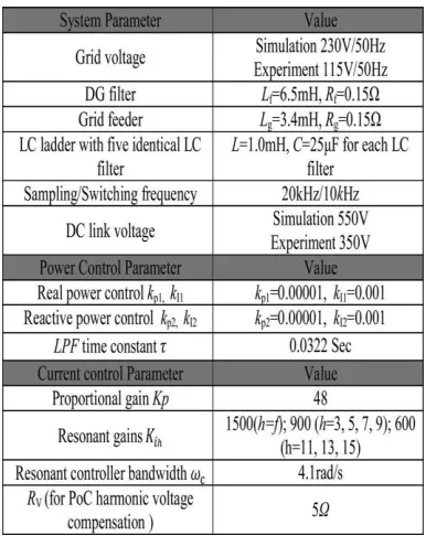
The DG unit with a local diode rectifier load is tested in the simulation. The configuration of the system is the same as shown in Fig. 1, and PoC is connected to a stiff controlled voltage source (to emulate the main grid) with nominal 50 Hz frequency. The main grid voltage contains 2.8% third and 2.8% fifth harmonic voltages. In this simulation, the reference power is set to 600W and 200 var. The detailed parameters of the system are provided in Table 1. When the local load harmonic current is not compensated by the DG unit [corresponding to Iref h = 0 the performance of the DG unit is shown in Fig. 6. It can be seen from Fig. 7 that the DG current is sinusoidal with 5.57% total harmonic distortion (THD).
The proposed method can still realize satisfied local load harmonic current compensation, resulted in an enhanced grid current quality with 5.88% THD. Meanwhile, DG unit current is polluted with 201.5% THD.
[image:5.595.352.545.450.693.2]
International Research Journal of Engineering and Technology (IRJET)
e-ISSN: 2395-0056Volume: 04 Issue: 08 | Aug -2017
www.irjet.net p-ISSN: 2395-0072© 2017, IRJET | Impact Factor value: 5.181 | ISO 9001:2008 Certified Journal
| Page 2144
Fig.6. Performance of the DG unit during DG harmonic rejection: (a) grid current Ig (b) DG current Idg
(c) Local load current I Local.
Fig.7. Performance of the DG unit during local load compensation: (a) grid current Ig,(b)DG current Idg
(c)Local load current I local.
Fig-8.Power flow of the DG unit during local load harmonic current compensation
(Pref = 600 W and Qref = 200 var).
Fig-9.Power control reference during local load harmonic compensation: (a) PoC voltage and fundamental current reference Iref; (b) power control
gains g1 and g2.
Fig-10 Performance of the DG unit under local harmonic compensation mode. (a)grid voltage Vgrid,
(b)grid current Ig (c) DG current Idg (d)Local load current Ilocal
CONCLUSION
International Research Journal of Engineering and Technology (IRJET)
e-ISSN: 2395-0056Volume: 04 Issue: 08 | Aug -2017
www.irjet.net p-ISSN: 2395-0072© 2017, IRJET | Impact Factor value: 5.181 | ISO 9001:2008 Certified Journal
| Page 2145
REFERENCES
[1] F.Blaabjerg, Z. Chen, and S. B. Kjaer, “Power electronics as efficient interface in dispersed power generation systems,” IEEE Trans. Power Electron, vol. 19, no. 5, pp. 1184–1194, Sep. 2004.
[2] F.Wang, J. L. Duarte, M. A. M. Hendrix, and P. F. Ribeiro, “Modeling and analysis of grid harmonic distortion impact of aggregated DG inverters,” IEEE Trans. Power Electron, vol. 26, no. 3, pp. 786–797, Mar. 2011.
[3] L.Asiminoaei, F. Blaabjerg, S. Hansen, and P. Thogersen, “Adaptive compensation of reactive power with shunt active power filters,” IEEE Trans. Ind. Appl., vol. 44, no. 3, pp. 867–877, May/Jun. 2008.
[4] L.Asiminoaei, F. Blaabjerg, and S. Hansen, “Detection is key—Harmonic detection methods for active power filter applications,” IEEE. Ind. Appl. Mag., vol. 13, no. 4, pp. 22–33, Jul./Aug. 2007.
[5] C.J.Gajanayake, D. M. Vilathgamuwa, P. C. Loh, R. Teodorescu, and F. Blaabjerg, “Z-source-inverter-based flexible distributed generation system solution for grid power quality improvement,” IEEE Trans. Energy Convers., vol. 24, no. 3, pp. 695–704, Sep. 2009.
[6] J. He and Y. W. Li, “Analysis, design and implementation of virtual impedance for power electronics interfaced distributed generation,” IEEE Trans. Ind. Appl., vol. 47, no. 6, pp. 2525–2038, Nov./Dec. 2011.
BIOGRAPHIES
Sk.Khadarbasha, received B.Tech from Audisankara College of Engineering & Technology, Gudur, AP, India. Currently pursuing M.Tech at Geethanjali Institute of Science Technology ,Nellore,AP,India.The research interest includes Harmonics reduction and Power quality.
Mr.K.Venkata Ravindra received M.Tech from PBR VITS, Kavali, Nellore(Dist.).Currently working as a Asst.professor at Geethanjal Institute
of Science &
Technology,Nellore,AP,India.