© 2017, IRJET | Impact Factor value: 5.181 | ISO 9001:2008 Certified Journal | Page 1463
DESIGN OF A COMPACT UWB ANTENNA FOR MIMO APPLICATIONS
Arunkumar Rayani
1Department of Electronics, St.Ann’s College Of Engineering & Technology,Chirala, India
---***---Abstract
—This paper proposes a compact ultra-wideband (UWB) multiple-input-multiple-output (MIMO) antenna with a dimension of 26 40 mm .The two antenna elements (PM1, PM2) are placed perpendicular to each other to achieve good isolation and fed with microstrip line, two long ground stubs are added to the ground plane to improve isolation and enhance impedance bandwidth A short ground strip is placed in order to make a common ground for two monopoles. A rectangular slot on both the monopoles decreases mutual coupling .Antenna parameters like reflection coefficients at the two input ports, coupling between the two input ports, radiation pattern are studied. The operating frequency is observed between 3.1-10.6(UWB) with a mutual coupling less than -15dB.IndexTerms--Multiple-Input-Multiple-Output(MIMO), Antenna
Microstrip feed, planar monopole, ultra wideband.
I. INTRODUCTION
ULTRAWIDEBAND (UWB) is a rapidly growing technology which makes use of wide frequency band to transmit signals at low energy level. It has promising applications in short-range high-data-rate transmission, radar imaging and cancer sensing. Since the authorization from the Federal Communications Commission in the US for unlicensed use of 3.1–10.6 GHz spectrum for applications with low power emission in 2002 [2] UWB systems have attracted attention. Like other wireless communication systems, UWB systems suffer from multipath fading. It is well-known that multiple-input- multiple-output (MIMO) technology can be used to provide multiplexing gain and diversity gain to improve the capacity and link quality, respectively, of wireless systems [3]. UWB systems using huge bandwidths already have high data rates, so MIMO technology can be used for fade countermeasure through diversity gain.
The basic concept of MIMO/diversity is to use multiple antenna elements to transmit or receive signals with different fading characteristics. Since it is unlikely that all the received signals will experience deep fading at the same time,
the system reliability can be increased by proper selection of the received signal. However installing multiple antenna elements on the small space available in portable
devices will inevitably cause severe mutual coupling and significantly degrade the diversity performance. Thus, one of the main challenges to employ MIMO technology in portable devices is the design of the small MIMO antennas with low mutual coupling.
Many MIMO antennas have been proposed for UWB systems [4]–[17]. In [4]–[11], various decoupling structures were employed between two symmetrically placed elements to Enhance isolation. In [12], [13], antenna elements of different types were combined to achieve pattern diversity. The antenna elements had distinct radiation patterns and polarizations, and so were able to receive signals with low correlation. In [14]–[17], perpendicular feeding direction are used to achieve polarization and pattern diversity. Among the aforementioned designs, some were not able to operate in the entire UWB band allocated by the FCC [4], [5], [8], [12], [13]. For those which could cover the entire UWB band [6], [7], [9]–[11], [14]–[17], some were not compact enough for portable devices [14]–[16]. For example, in [14], a complicated 3-D feeding network with a large volume was required. In [15], [16], the sizes of the MIMO antennas were 80 80 mm . For the rest of these designs, the MIMO antenna proposed in [7] had the smallest size of 5 = mm Good isolation was achieved by inserting a tree-like structure between the two antenna elements.
© 2017, IRJET | Impact Factor value: 5.181 | ISO 9001:2008 Certified Journal | Page 1464
II. ANTENNA DESIGN
The schematic configuration of the proposed Multiple-Input Multiple-Output antenna with ultra wideband frequency is shown in Fig.1. For the design, the radiating patch is etched on the substrate of dielectric constant 4.4 and thickness of 0.8mm. The proposed MIMO antenna consists of two planar monopole antennas denoted by PM1, PM2 in Fig. 1 which are fed by 50- microstrip line with a dimension of Wf
Lf the two square radiators have identical dimensions The
ground planes of PM 1 and PM 2 have the same width of G
but different lengths of WG and L respectively and are printed
on the other side of the substrate. A short ground strip with a size of LS3 WS3 is used to electrically connect the two
ground planes together, forming an L-shaped common ground for both PMs. A small rectangular slot is cut on the upper edge of the ground plane under each feed
TABLE I : DIMENSIONS OF PROPOSED ANTENNA (MM)
L Lr Lf Ls1 Ls2 Ls3 lfs Df1 DS lr
26 10 9 17 16 3 4 6.1 5 7 W LG Wf Ws Lss1 Ws3 Wfs Df2 WG --
[image:2.612.36.296.333.629.2]40 8 1.8 1 5 1 1 8.1 29 --
Fig. 1. Geometry of proposed antenna ( top layer and bottom layer)
line to increase impedance matching at higher frequencies enhance isolation and increase impedance bandwidth, two long ground stubs shown in Fig. 1, are employed. Stub 1 is
bent in an angle to reduce the overall antenna area, while stub 2 is a straight stub placed in parallel with PM 2. A slot with a dimension of lr Wf is made to decrease mutual
coupling to some more extent The Computer simulation using the EM simulation tool CST is carried out to study and the proposed MIMO antenna in terms of impedance bandwidths, radiation patterns and with input signal at either of the two input ports, and isolation between the two input ports. The optimized dimensions for the MIMO antenna are listed.
III. RESULTS AND DISCUSSION
This part will discuss the performance of proposed MIMO antenna by using computer simulation The simulated S11 S22 S21 plots for the UWB MIMO antenna designed in this
paper is shown in Fig.2, Fig.3, Fig4 respectively. The result in Fig.2 and Fig.3 shows that for port 1 and port 2 S11 < -10dB in
the entire UWB range and so satisfying impedance matching requirement for the entire UWB specified by the FCC.
© 2017, IRJET | Impact Factor value: 5.181 | ISO 9001:2008 Certified Journal | Page 1465
Fig 3: S22 plot for the proposed antennaMutual coupling less than 15 dB is considered enough for good performance [7], [11], [15], [16]. Fig.4 shows the simulated S21 [mutual coupling] between the two input
ports Fig.4 shows that the mutual coupling is less than -15dB across the entire UWB bad and so this makes the proposed antenna suitable for MIMO applications in the UWB range
Fig 4: S21 plot for proposed antenna
In order to operate an antenna efficiently, maximum power must be transferred between the transmitter and the antenna. Maximum power transfer can take place only when the impedance of the antenna is matched to that of the transmitter. The higher the VSWR, the greater is the mismatch. VSWR plot for the proposed antenna is shown in Fig.4. From the plot, it can be observed that VSWR is less than or equal to 2.5 in the radiating frequency. Thus, the mismatch is very less in the radiating band.
Fig 4(a): VSWR for PM
Fig 4(b): VSWR for PM2
© 2017, IRJET | Impact Factor value: 5.181 | ISO 9001:2008 Certified Journal | Page 1466
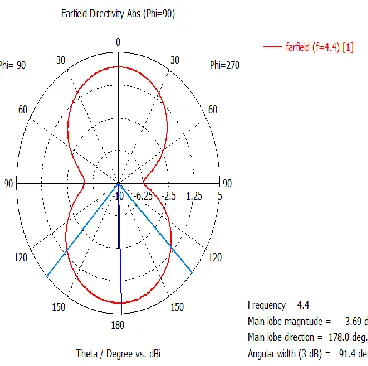
Fig 5: Polar plot at resonating frequency f = 4.44GHzFrom the figures, it can be observed that the radiation is maximum at an angle 178o at resonating
frequency 4.44GHz for PM1 while for PM2 the radiation is maximum at an angle of 177o at resonating frequency
[image:4.612.102.286.103.286.2]4.44GHz
Fig 6: Polar plot at resonating frequency f= 4.44GHz
IV.CONCLUSION
In this paper, a compact MIMO antenna is designed and simulated. The presented antenna contains two PMs in order to achieve good isolation between the two input ports they
are placed perpendicular to each other. To improve isolation two long stubs are placed adjacent to radiating element and a short ground strip is employed to connect two ground planes The proposed antenna is simulated using computer simulation technology and results shown that the antenna can be operated in the entire UWB band from 3.1 to 10.6 GHz with mutual coupling of less than -15dB between the ports All results indicate that the MIMO antenna is a good candidate for portable UWB applications.
REFERENCES
[1] Li Liu, S. W. Cheung and T. I. Yuk “Compact MIMO Antenna for Portable Devices in UWB Applications” IEEE Trans on Antennas and Prop, Vol. 61, No. 8, August 2013
[2] Federal Communications Commission (FCC), Revision of Part 15 of the Commission’s Rules Regarding Ultra-Wideband Transmission Sys-tems First Rep. and Order, ET Docket 98-153, FCC 02-48, Adopted: Feb. 2002; Released, Apr. 2002.
[3] L. Zheng and C. Tse, “Diversity and multiplexing: A fundamental tradeoff in multiple-antenna channels,”
IEEE Trans. Inf. Theory, vol. 49, pp. 1073–1096, May 2003.
[4] K. L. Wong, S. W. Su, and Y. L. Kuo, “A printed Ultra-wideband diversity monopole antenna,” Microw. Opt. Technol. Lett., vol. 38, no. 4, pp. 257–259, 2003.
[5] L. Liu, H. Zhao, T. S. P. SEE, and Z. N. Chen, “A printed ultra-wide-band diversity antenna,” in Proc. Int. Conf. on Ultrawideband (ICUWB’2006), Waltham, MA, USA, Sep. 2006, pp. 351–356.
[6] S. Hong, K. Chung, J. Lee, S. Jung, S. S. Lee, and J. Choi, “Design of a diversity antenna with stubs for UWB applications,” Microw. Opt. Technol. Lett., vol. 50, no. 5, pp. 1352–1356, 2008.
[7] S. Zhang, Z. Ying, J. Xiong, and S. He, “Ultrawideband MIMO
diversity antennas with a tree-like structure to enhance wideband isolation,”
[8] T. S. P. See and Z. N. Chen, “An ultrawideband diversity antenna,” IEEE Trans. Antennas Propag., vol. 57, no. 6, pp. 1597–1605, 2009.
[9] Y. Cheng, W. J. Lu, and C. H. Cheng, “Printed diversity antenna for ultra-wideband applications,” in Proc. Int. Conf. Ultrawideband (ICUWB’2010), Nanjing, China, Sep. 2010, pp. 1–4.
© 2017, IRJET | Impact Factor value: 5.181 | ISO 9001:2008 Certified Journal | Page 1467
Propag., vol. 5, no. 12, pp. 1463–1470, 2011.
[11]J. M. Lee, K. B. Kim, H. K. Ryu, and J. M. Woo, “A compact ultrawide-band MIMO antenna with WLAN band-rejected operation for mobile devices,” IEEE Antennas Wireless Propag. Lett., vol. 11, pp. 990–993, 2012.
[12]A. Rajagopalan, G. Gupta, A. S. Konanur, B. Hughes, and G. Lazzi, “Increasing channel capacity of an ultrawideband MIMO system using vector antennas,”
IEEE Trans. Antennas Propag., vol. 55, no. 10, pp. 2880–2887, 2007.
[13]S. Zhang, B. K. Lau, A. Sunesson, and S. He, “Closely-packed UWB MIMO/diversity antenna with different patterns and polarizations for USB dongle applications,” IEEE Trans. Antennas Propag., vol. 60, no. 9, pp. 4372–4380, 2012.
[14] G. Adamiuk, S. Beer, W. Wiesbeck, and T. Zwick, “Dual-orthogonal polarized antenna for UWB-IR technology,” IEEE Antennas Wireless Propag. Lett., vol. 8, pp. 981–984, 2009.
[15]E. A. Daviu, M. Gallo, B. B. Clemente, and M. F. Bataller, “Ultra-wideband slot ring antenna for diversity applications,” Electron. Lett., vol. 46, no. 7, pp. 478–480, 2010.
[16]M. Gallo, E. A. Daviu, M. F. Bataller, M. Bozzetti, J. M. Pardo, and L. J. Llacer, “A broadband pattern diversity annular slot antenna,” IEEETrans. Antennas Propag., vol. 60, no. 3, pp. 1596–1600, 2012.
[17]Y. C. Lu and Y. C. Lin, “A compact dual-polarized UWB antenna with high port isolation,” in Proc. IEEE Antennas Propag. Society Int. Symp. (APSURSI’2010), Toronto, ON, Canada, Jul. 2010.
[18]L. Liu, S. W. Cheung, Y. F. Weng, and T. I. Yuk, M. A. Matin, Ed., “Cable effects on measuring small planar UWB monopole antennas,”
Ultra Wideband—Current Status and Future Trends, Oct. 2012.
[19]M. B. Knudsen and G. F. Pedersen, “Spherical outdoor to indoor power spectrum model at the mobile terminal,” IEEE J. Sel. Areas Commun., vol. 20, no. 6, pp. 1156–1168, Aug. 2002.