© 2017, IRJET | Impact Factor value: 5.181 | ISO 9001:2008 Certified Journal
| Page 2920
Precise Flow Control Using Microcontroller For Insulin Infusion
Process
Shashank B.Surywanshi
1, D.G.Chougule
21
M. E Eln, Tatyasaheb Kore Institute of Engg & Tech, Warananagar. Kolhapur, Maharashtra, India
2
Professor in Etx, Tatyasaheb Kore Institute of Engineering & Technology, Warananagar. Kolhapur, Maharashtra,
India.
---***---Abstract –
for today’s life in every aspect automation isrequired to reduce the work. So we have designed Automatic flow control system for Insulin Infusion Process as well as for general precise flow control industrial applications. This System will overcome the current drawbacks of insulin flow control pump used for injection of insulin into the body of diabetes patients. Infusion pumps can deliver fluids in way that would be impractically expensive or unreliable if done manually by any person .For example, delivering rate of fluid or liquid or medicine as small as 0.1ml per hour and this is continuous process of injection for many hours with change of delivering rate. The MBFC system is having unit to measure the patient’s blood glucose level and accordingly automatically adjusts the flow of insulin through the pump. This system can also be used for precise flow control of biomedical fluids as well as medicines and industrial fluids or liquids. Through the MBFC System any single medical staff in hospital ICU can do all the things from sugar measurement to final Insulin doses adjustment, So in absence of responsible doctor the MBFC can take care of all the necessary things with reduced man power. The proposed system has blood glucose measuring unit through which the nurse or doctor can measure patient’s blood glucose level in time and accurately there after the insulin flow into the body of patient is adjusted or set. The Insulin pump flow can be set automatically on the amount of sugar or manually by the nurse or doctor as according to the need. The Proposed system is having three IPs running at a time and also having PC interface through which the total control and setting can be made.
Key Words:
MBFC, Insulin Pump(IP), BGM, Precise Flowcontrol.
1. INTRODUCTION
The ability to control and manipulate fluid flows in present technological benefits has a wide range of applications in both man-made and natural systems that have fluid flow in or around them. In recent years, flow
control has become a highly multi-disciplinary research activity encompassing theoretical, computational and experimental fluid dynamics, acoustics, control theory, physics, chemistry, biology and mathematics. Flow control for fluids or liquids or medicines has many applications. In the field of bio-medical the most effective treatment method for the diabetics is long-term insulin injecting, for which currently open loop insulin infusion pumps are used. As todays demand is low cost and more automation a novel design of automatic insulin injection process using microcontroller is put forward. It can realize the accurate setting, storage and display for the insulin dosage, and drive a miniature stepper motor to push the insulin into the patient’s body automatically and accurately, which is very convenient for the diabetics to manipulate and ensures a best therapy effect as well. Also this syringe can infuses fluids, medication or nutrients into a patient's circulatory system. There are wide applications for flow control almost in all engineering fields from automobile for small dispense of fuel into the ignition system to chemical and food processing where concentration and quantity of food products plays an important role. So MBFC system is the need for today’s fields where there is a demand of precision, accurate and controlled fluid infusion for many hours is required. As the inventions in biomedical field increasing continuously MBFC system is such a system which fulfills all the aspects of the Insulin infusion Process because the system provides quite high but controlled pressures for the flow and also provides Central control on the flow operation for three patients at a time.
2. SYSTEM DESCRIPTION
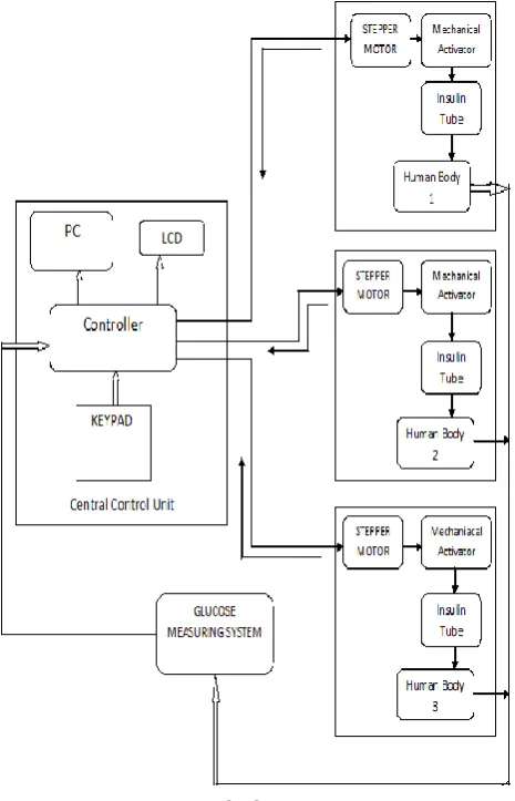
The Microcontroller based flow control for Insulin Infusion Process consists of main four sections as shown in Fig. 01.
[1] Glucose measuring Unit. [2] Controlling Unit.
[3] Three Patient Controlled Units. [4] PC Interface Unit.
© 2017, IRJET | Impact Factor value: 5.181 | ISO 9001:2008 Certified Journal
| Page 2921
glucose measuring system consists of glucometer sensorfollowed by data processing parts, keypad and LCD. On three controlled units or receiving units there are three patient bodies connected to respective IPs & the total insulin injection process will going to be carried out at the same time from single controlling unit.
Fig -1
: Block Diagram
Insulin injection process is having selectable rate insulin tube or syringe for the delivery of insulin or other similar medication, including selection of the interval between motor-driven syringe advance and including control of the plunger displacement for delivery of an insulin bolus of predetermined size. Process is having slow-rate, highly accurate dispensing which can be used to inject small amounts of medication at a relatively constant rate for days at time.
Circuit of the IP system is mainly made up of the driver unit for the stepper motor, and alarm circuit . The MCU is the core of the whole system to set injection dose, store and dynamically display. When patients with diabetes are injected, the controller will send pulses with certain frequency to the stepper driver unit.
The stepper driver module provides enough current to drive the miniature stepper motor, which
propels the actuator to push the piston inside the liquid container and finish the injection with a preset dose and also doses goes on adjusted according to the feedback of blood glucose level of the particular patient.
The human-computer interaction module is consisted of key and stroke segment LCD parts with additional feature of direct PC interface also, provides total system control from single computer, which is used to complete such interactive operations as dose set in automatic & manual mode settings. In case of power failure Control unit can be driven through battery supply and system operation is carried using keypad & LCD. Through PC control the system is best to use which is having three different windows for the three controlling units. In PC control mode first the mode is selected i.e. Auto or Manual for each patient or controlling unit then the amount of patient sugar is measured using BGM unit. The measured sugar appears on the respective patient window and the IPs speed adjusted according to the mode selected.
3. HARDWARE ORIENTATION
1.Power supply:
In the circuit using IC 7805,IC7812. we can get +5V AND +12V DC supply.
In the circuit, +5V DC supply is required for: AVR ATMEGA16
LCD Display
And +12V DC supply is required for: DRV 8825.
Stepper motors.A. The controller
This kind of MCU is ATmega32 - featuring, High-performance, Low-power AVR with 8-Bit RISC architecture and rich peripheral resources and so on. RTC module provides an exact real-time clock for the system. Some dual I/O functions , such as supporting stroke segment LCD driver, comparing capture model, PWM wave output (CCP), supporting BSL mode of download, are utilized in the application. Controller takes the data from BGM unit process the data display the amount of sugar on LCD or PC and accordingly takes the decision of Insulin flow adjustment. The role of controller is to do multiple tasks such as sort the sugar value measured according to the patient and adjust or set the speed of respective IP only without disturbing the other patients IP.
B. The driver unit for the stepper motor.
[image:2.595.59.292.172.534.2]© 2017, IRJET | Impact Factor value: 5.181 | ISO 9001:2008 Certified Journal
| Page 2922
and designed for low voltage portable applications. Thechip has micro, full and half-stepping capability. Three driver units along with three mechanical assemblies take care of the accurate Insulin flow adjustment. To reduce the flow rate to required range proper gearing mechanism is used along with DRV 8825 micro-stepping feature. The working of DRV is controlled by the controller by software as well as by hardware means.
C. Human-Computer Interaction unit
Human-Computer Interaction unit is composed of two parts: the stroke segment LCD screen, the membrane switches and computer with controller interface. The LCD along with keypad is used in case of actual monitoring person or nurse presence or any power failure case where we are not able to use the PC interface. Through keypad the mode is selected like automatic injection or manual injection of insulin, Measured sugar is displayed on the LCD and accordingly speed of IPs are set. Also it is having the feature to stop the IPs & reverse movement of the pumps. When it is time for the patient to inject, only needs to press the Injection button. With the of second part having direct PC interface, there are three different controlling windows for the three patients. First select the mode of operation of IPs, then it automatically takes the sugar data via serial port as the blood sugar is measured through BGM unit and accordingly adjusts the three IPs with respect to respective blood glucose amount of each patient. As the injection process going on any time we take the amount of blood glucose level which will be displayed on the PC screen and therewith doses goes on adjusted automatically. It is having feature to measure the blood glucose and adjust the IPs speed in run time. Also having feature to control & monitor individual patient. In run time any patients IP can be stopped or moved back without disturbing the other patients status.
D. Blood Glucose Measuring Unit
This unit was facilitated with glucometer sensor, keypad, controller, LCD display. Blood of the respective three patients is taken after some intervals on the completion of insulin doses and the glucose level was check in this unit which is then fed to control unit to take the corresponding decisions of insulin doses. The measured blood sugar is displayed on the LCD or on the PC GUI according to the selected mode. Same BGM unit is used for the three patients but at a time only single patients sugar is measured and not simultaneously.
4. TESTING AND SIMULATION RESULTS
Part 1: Blood Glucose Measuring Unit
The blood sugar concentration is the amount
of glucose (sugar) present in the blood of a human or animal. The glucose sensor is electrochemical strip which is having glucose oxidase enzymes. Our existing glucometer employs glucose dehydrogenase to generate
electrons on a strip covered with blood, and the change in voltage across the strip is measured over time to determine glucose concentration. This method is called Amperometric Method of blood glucose measurement.
Resistance across the strip drops over time due to the chemical reaction on the strip and the increase in the product of the enzyme-catalyzed reaction. Measurement of the corresponding voltage drop is correlated with known blood glucose concentrations to determine the patient’s blood glucose concentration.
The enzyme on the strip acts as a bio-recognition element, which recognizes glucose molecules. The enzyme molecules located on an electrode surface, which acts as a transducer. glucose molecules are recognized by the enzyme and acts as a catalyst to produce gluconic acid and hydrogen peroxide from glucose and oxygen from the air. The electrode recognizes the number of electron transfer due to hydrogen peroxide coupling. The electrons flow is depends to number of glucose molecules present in blood. The glucose sensor is an electrochemical strip which uses glucose oxidase enzymes in conjunction with three electrically conductive electrodes. The glucometer strip is having three electrodes namely working electrode, reference electrode and counter electrode. When blood is placed onto the test strip, it reacts with a enzyme due to that amount of glucose in the blood turns either into gluconic acid or gluconolactone, depending on the type of reagent used on the strip.
Fig-2: Glucometer Strip
Chemical reaction at reaction zone
GODGlucose +O
2+ H
2O Gluconic acid + H
2O
2H
2O
2O
2+2H
++ 2e
-J1 CON3 1 2 3 + -U3 LF356 3 2 6 7 1 4 5 C1 CAP VCC_ARROW J3 CON2 1 2 + -U1A LM358 3 2 1 8 4 R2 RESISTOR VCC_ARROW J2 CON2 1 2
© 2017, IRJET | Impact Factor value: 5.181 | ISO 9001:2008 Certified Journal
| Page 2923
The signals from glucose sensor which is change in currentare passed to signal condition unit. This output of the Biosensor collected at working electrode is connected to amplifier LM358. The glucometer requires 220 millivolts maintained across the two electrodes using LM358 Op-Amp.One of the electrodes is a reference electrode and the other is the working electrode. The reference electrode is connected to electrical ground (common), and the working electrode is maintained at 220 mV. When a blood sample is placed on the test strip, the resistance of the strip immediately drops, causing current flow proportional to amount of blood molecules . The average current produced by the glucose test strip is 20μA. The output of LM 358 is given to the filter circuit. The current is converted to voltage through a current-to-voltage converter made with the help of LF356 which also acts as Low Pass Butterworth filter. A current to-voltage converter is simply an op amp with a feedback resistor. The output voltage from LF356 is in the rage of 1-10 mv. Both LM358 & LF356 required external bias voltage of range 2-3 volts.
Fig-4: waveform of voltage at pin 6 of LF356
This output is actual voltage signal corresponding to the amount blood glucose. In the fig 03 if strip with blood sample is placed at con3 location initially the output voltage of LF356 increases rapidly for 1-2 sec time period proportional to blood glucose amount and then settle to a stable value after 2 seconds. This analog voltage is connected to ADC pin of ATmega32. We taken average of all voltage values at the output in the controller and then calculated the mean value after 2 seconds to measure the actual blood glucose of the patient.
Fig-5: Blood Glucose displayed on LCD.
Part 2: Central Control Unit with keypad & LCD
In the central control unit via keypad and LCD depending on measured glucose concentration IPs speed is adjusted. Single BGM unit is used for three patients so first and main function of the ATmega32 is to sort the measured blood glucose value according to the patient. User has the flexibility to use either hardware or PC software mode to use the total MFC system. As firstly the system started all the IPs are off ,to start any pump first we select the auto or manual mode via keypad & LCD,then select the particular patient i.e its IP. Now first measure the blood glucose of the patient through BGM unit with a single switch and sort the value according to the patient under observation. Depending on amount of glucose adjust the speed manually in manual mode of operation and in automatic mode the control unit itself sets the speed of IPs on the basis of previously loaded data of blood glucose speed chart. For the automatic mode this blood glucose speed chart is set in software itself according to the demand of doctors. This chart gives information about for what amount of sugar value what will be the required speed of IPs. So on the amount of sugar value ATmega32 automatically go on adjusting the speed of IPs in automatic mode of operation. The Particular IP is started with the frequency pulses from the ATmega32 to the DRV 8825, which then provides 4 output pulses to the stepper motor to rotate it. The controller is having hardware toggle mode on compare match, this feature of ATmega32 is used to drive three DRV8825 at the same time without interrupt or interference with each other. The minimum speed of any IP is 0.1ml/hr and maximum is 10ml/hr.
In ICUs for the diabetes patients the speed of IP is adjusted with respect to amount of sugar i.e if the blood sugar concentration is large then high speed is set on IP to inject or infuse more amount of insulin into the body of patient. Likewise the programming is done for the full user interface with the system. For the low speed of IPs controller generates low frequency square wave signal to respective DRV 8825 and for high speed of IP the controller will generate high frequency square wave. Also the controller does the role of direction controlling of the stepper motors to run in forward(clockwise) or backward(anticlockwise),stop the motors or to move back the motors to their initial positions.
© 2017, IRJET | Impact Factor value: 5.181 | ISO 9001:2008 Certified Journal
| Page 2924
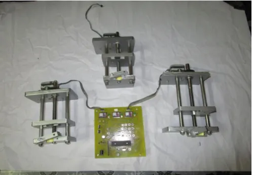
Part 3: Three Patient Controlled Units.In the project the three patient controlled units are actually three IPs. Each of the Insulin pump controlled by stepper motor. So to interface three IPs to ATmega32 three Driver ICs DRV8825 are used.2 Pins of controller controls a single IP so total of 6 pins of controller controls all the three IPs full operation. 3 pins of ATmega32 are used to set the direction of three IPs i.e forward or reverse, and 3 pins to run the IPs with proper frequency or speed with the use of DRV8825. As the case with this driver to drive one stepper motor the driver requires only 2 pins of controller also the resolution of stepper motor can be increased as this driver can rotate the stepper motor in any mode i.e. half drive, full drive, wave drive or most important micro-stepping drive mode.
Fig-7: DRV8825 Pin diagram and required drive current waveform.
Fig-8: Actual Implemented total System.
Part 4: PC Interface Unit.
To control the MBFC system we have two options one is hardware control mode i.e via keypad and LCD and second is software control mode i.e via PC GUI Control. This GUI Control panel is made with C Sharp programming language. To control the total system through PC, UART serial communication protocol used with standard baud of 9600 along with CP2102 chip USB to UART bridge. The GUI control is having three windows for the three patients along with all the modes of operation. These modes includes automatic IP flow rate adjust mode, manual IP
flow rate adjust mode, move IP back mode and IP stop mode. The measured blood glucose of the patient is transmitted to PC GUI in patients respective window. Then according to requirement user will set the mode and then the data having mode information is transmitted back to the controller to adjust the flow rate of IP. In run time user has the flexibility to adjust any mode of the above without system interrupt or without disturbing the rest of IPs.
1. On the amount of Blood glucose value for the respective patient, Individual Insulin Pumps delivering rate can be set or varied by changing values from GUI of PC connected to the system. The GUI is having Individual window with all controls for each patient.
2. Simultaneously for all the three Insulin pumps delivering rate can be set or varied through the PC. 3. Through PC GUI, for the three IPs can be provided
with back motion and stop state.
Fig-9: Selecting Automatic or Manual Mode
Blood Glucose
IP delivering rate
100-150 mg/dl
0.1ml/hr
150-200 mg/dl
0.2ml/hr
200-250 mg/dl
0.4ml/hr
250-300 mg/dl
0.6ml/hr
300-350 mg/dl
0.8ml/hr
350-400 mg/dl
1ml/hr
400-450 mg/dl
1.5ml/hr
[image:5.595.41.256.330.392.2]450-500 mg/dl
2ml/hr
[image:5.595.308.560.353.530.2] [image:5.595.38.288.441.613.2]© 2017, IRJET | Impact Factor value: 5.181 | ISO 9001:2008 Certified Journal
| Page 2925
5.System Flow chart
6. CONCLUSIONS
The aim of this work was to demonstrate a total system for Controlled Insulin Infusion Process with closed loop configuration. In ICU there is detailed and clear observation on patients condition is required. As the case with diabetes patients in ICU Our MBFC system provides all the necessary things with reduced manpower with less doctor interaction .Initially the doctor takes care of all the things about patient condition and speed adjustment according to the modes and later he will reliable on his staff for the total observation of patients. The BGM unit with its flexibility to use for any patients with total system interface gives intime and correct value of blood sugar. On the account of BGM unit sugar value directly feed to the system so the record keeping becomes easy and suitable The designed Microcontroller based flow control system for Insulin Infusion process provides close loop system with automatic speed adjustment of Insulin Pumps without stopping or interrupting them. Also through PC interface the total system becomes more easy to use. In designed system it provides control for Three ICU patients which can also be increased so a single staff can take care of all the patients from a single control unit from a single PC. As all the necessary units for the Insulin Infusion process comes under a single system through this project it becomes more cost effective and more economical as well. In present MBFC system out-off four units two are successfully simulated. Hence this system proves to be very advantageous as well as efficient, the one which might become the bench mark in the history of automation.
REFERENCES
[1] Konstantia Zarkogianni, Stavroula G. Mougiakakou, Aikaterini Prountzou, Andriani Vazeou, Christos S. Bartsocas, and Konstantina S. Nikita“An Insulin Infusion Advisory System for TypeI Diabetes Patients based onNon-Linear Model Predictive Control.Methods”
Proceedings of the 29th Annual International Conference of the IEEE EMBS,August 2007, pp.23-26.
[2] Wenrui Zhao, Qi Wang, Qingbo Zhan, Jianjun Zhuang, Xinbao Ning, “Design of Portable Insulin Syringe Based on MSP430 MC” 3rd International Conference on Biomedical Engineering and Informatics of the IEEE BMEI,978-1-4244-6498-2/10/$26.00
©2010,pp.1459-1462.
© 2017, IRJET | Impact Factor value: 5.181 | ISO 9001:2008 Certified Journal
| Page 2926
First International Conference Biomedical Engineering and Informatics IEEE, 2006, pp.65-68.
[4] Prof. Smita R.Dikondwar, “Micro Flow rate Infusion Pump Prototype” International Journal of Advanced Research in Computer Science and Software Engineering Volume 3, Issue 7, July 2013,pp.315-318.
[5] Inventors-Brian Pope, Zhan Liu, “Syringe pump rapid occlusion detection system” US Patent, Publication number-EP1616589 B1, Dec 2009.
[6] Inventors Morten Mernoe, Mitchell Wenger, James Causey, Todd Kirschen, “Dispensing fluid from an infusion pump system” US Patent Publication number US8747369B, June 2014. [7] Stoianovici, D. ; Patriciu, A. ; Petrisor, D. ;
Mazilu, D.; Kavoussi, L, “A New Type of Motor:Pneumatic Step Motor” 7th International Conference on Electronics Packaging Technology IEEE ,Volume: 12 , Issue: 1 ,July 2007.
[8] Medtronic Website.“Real-time Continuous glucose monitoring system”,2008 Online available at http://www.medtronic.com. [9] “2466S–AVR–05/09 datasheet,” 2009 Atmel
Corporation, Atmel®. &“Oct 1991,L293E Datasheet,”1994 SGS-THOMSON.