PSNR Comparison of Lifting Wavelet Decomposed
Modified SPIHT Coded Image with Normal SPIHT Coding
Ashish Nautiyal
Scholar of M.Tech U.T.U. Dehradun (India)Isha Tyagi
Scholar of M.Tech U.T.U. Dehradun (India)Mukesh
Pathela
Assistant Professor S.C.E. Dehradun (India)
ABSTRACT
Today’s world is the era of communication i.e. sending some information from one point to another. And images are one of the commonly used multimedia, because of the application in almost every field of engineering i.e. biomedical, astronomical, geological etc. To make communication fast and efficient with respect to images, compression is needed in each and every field. Idea behind the work is to reduce the size of image at transmitter end and after sending it to the receiver, regenerate it again to its original form. But to attain a measurable amount of compression, there are always some losses (compromise on resolution) at receiver end. The measure of efficiency of compression coding depends upon the balance between resolution and compression ratio of images. So aim of every coding scheme is to make a good trade-off between resolution and compression ratio so that we can achieve a fast communication with a good regenerated image at the receiver end.
In this work, compression is based on wavelet transform. Wavelet is an important tool to covert spatial domain representation into frequency domain which is not based on a fundamental frequency of sine or cosine waveform of infinite period of time but finite numbers of short waves of different frequencies which give the best result for high frequency components as well as for low frequency (long time period) components too. After transforming the image, lower and higher energy parts can be easily differentiated and quantization can be applied to truncate the unnecessary lower energy parts where higher energy is kept preserve.
For coding of transformed image, a Set Partitioning in Hierarchical Tree (SPIHT) coding algorithm is used. After the transformation, SPIHT coding scheme basically code high energy components first and progressively transmits the coded bits to make an increasingly refined copy of the original image. A modified SPIHT coding is presented in the work for progressive transmission.
Keywords
Discrete Wavelet Transform (DWT), Lifting Wavelet Transform, Image compressing, Set Partitioning in Hierarchical Tree (SPIHT)
1.
INTRODUCTION
The objective of this paper is to improve the compression algorithm by using lifting wavelet transform and modified Set Partitioning in Hierarchical Tree compression algorithm, and compare the PSNR plot with normal SPIHT method.
The problem is useful in all applications of image compression like Biometrics, biomedical Imaging for
diagnosis of disease, and in some others imaging applications like photography, image browsing, multimedia, etc. Other application is in the transmission of information in progressive manner given to the bit stream.
In this paper it has been shown that PSNR is being improved by 8% for practical image. Modified scheme is also giving very less value of MSE with great amount of improvement. Execution time of coding is the factor which is very important for transmitting data so it should be less to make the transmission fast. In modified scheme execution time is being improved by approximately 10 sec or more. So overall modified SPIHT coding method is giving improved result over normal SPIHT coding when used with lifting wavelet technique.
2.
LIFTING IN DWT
The Wim Sweldens built up the lifting scheme for the structure of bi-orthogonal wavelets. The most important feature of the lifting scheme is that structures are derived in the spatial domain. This does not need complex mathematical calculations which are required in conventional methods [5]. Lifting scheme is easiest and efficient algorithm to determine wavelet transforms. It does not depend upon Fourier transforms. This scheme is used to produce second generation wavelets that are not essentially translation of one particular function.
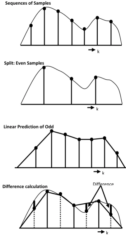
Making wavelets with the help of lifting scheme mainly consists of three major steps. The first step is to split phase which split data into odd as well as even sets. The next step is predicting step in which odd set is predicted from even set. This phase ensures the polynomial cancellation on high pass. Third step is to update phase which will update the even set using wavelet coefficient for calculating scaling function. This stage ensures conservation of moments on low pass [5]. The fundamental idea of wavelet transform is to take advantage of correlation present in most real life images to build meager approximation. Correlation is local in both frequencies as well as in time domain. Conventional wavelet transform uses wavelet filters for building time-frequency localization. In this section, it will be discussed how to obtain lifting steps from wavelet filters.
2.1.1
Poly-phase representation of function
Let’s consider the sequence of samples of a signal f (k). Now Z-transform of sequence can be given as:
Let’s consider finite-impulse-response (FIR) filter h, having filter coefficients . Z-transform of the function is given by:
(2)
Sub-sampling of the function is equivalent to keeping only the even samples which is given by . Z-transform of the sub sample function is given by:
(3)
After calculating and we can give the expression:
(4)
Similarly
(5)
So from equation 4 and equation 5 we can represent function as:
(6)
Equation 6 is representing how we break the function in even and odd parts.
2.1.2
Primal Lifting (Updating) and Dual Lifting
(Predicting)
In DWT the for corresponding scaling and wavelet function in wavelet transform there are filter banks h and g in this step two types of lifting is performed and these filters are updated.
Using a primal lifting new filter which is complementary to g is formed by filters h and g.
(7)
Using dual-lifting, new filter which is complementary to h is created from filters h and g.
[image:2.595.339.542.340.718.2](8)
Fig. 1. Three lifting steps of forward wavelet transform Even and odd samples are interleaved. If the signals are having locally correlated structure, in that case even and odd samples are extremely correlated. Then it is very simple to predict odd samples from even samples. In order to accomplish maximum data compression, prediction has to be powerful. And in order to build powerful predictor, we have to know nature of the signal. We would like to characterize data more compactly to reduce storage requirement as well as to reduce transmission bandwidth and rate. If we can use
dominant prediction mechanism, we can characterize data more compactly. The coarser signal has to have same average value with respect to original signal as shown in Fig. 2..
3.
SET PARTITIONING IN
HIERARICHAL TREE (SPIHT)
In SPIHT a modified form of embedded coding of wavelet coefficients is performed which carries the major strengths of EZW, namely ordered coefficient transmission and self-similarity across subbands of similar orientation. In accumulation, first it partitions the set of coefficients into subsets of insignificant coefficients and then identifies each significant coefficient [2]. The approach which is proposed by Said and Pearlman is called as Set Partitioning in Hierarchical Trees (SPIHT). At some identical target bit rates, experimentations have revealed that SPIHT algorithm has modified the performance over EZW, because of its capability to exploit the grouping of insignificant coefficients [2]. The objective of this lesson will first present some of the basics of progressive image transmission and later introduce the concepts of set partitioning. In this the encoding algorithm will be explained and then we should be able to design and implement a SPIHT coder and decoder with the help of this theory.
Fig. 2. Method for lifting scheme of wavelet transform Even Samples 𝑊∅ 1,
+
𝑊∅ 0, Split Predict Update
Sequence Odd value Stage
Odd Samples 𝑊𝜓 1,
Sequences of Samples
Split: Even Samples
Linear Prediction of Odd Samples
Difference calculation
k
k
k
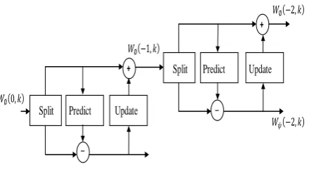
[image:2.595.55.277.524.649.2]Fig. 3. A multi-level wavelet transform with lifting scheme
3.1
Spatial Orientation Tree
The spatial orientation tree, demonstrated in fig. characterizes the spatial relationship between the subbands in the form of a pyramid collected of a recursive four-band split. In this each node of the tree corresponds to a pixel and is easily identified by its pixel coordinate. Moreover other than leaves, each node of the tree has its four offspring exactly equivalent to the pixel at the same position in the next finer level of the pyramid of similar orientation, as revealed by arrows in the diagram [9]. The only extraordinary case, is the LL subband existing at the highest level of pyramid. Basically pixels in this subband form the root and groups of adjacent 2x2 pixels [7]. Other than one of the pixels out of these four, all lasting three pixels have their four offspring in the HL, LH and HH subbands of the equal scale, as shown. Only three subbands exist for determining the descendants since one out of the four is obviously left out.
The spatial orientation tree which is discussed above has close similarity with the hierarchical tree structure that was used to inspect the zerotrees and the corresponding zerotree roots in EZW algorithm. However, there is a foremost difference too. In the hierarchical tree of EZW, each and every LL subband pixel at the highest level has mainly three offspring at the HL, LH and HH subbands, whereas offspring relationship of LL subband pixels in the spatial orientation tree is same which has been already discussed [9].
3.2
Rules for Set-Partitioning
First we will define the following sets before presenting the set partition rules here:
: It is known as the offspring set. It actually contains the coordinates of the pixels, which are basically offspring of the node .
: It is the descendant’s set. It actually contains all the coordinates of the pixels which are basically descendants of the node .
: The difference set of and . It therefore holds the descendants of the node , other than the offspring.
: This set contains the coordinates of all spatial orientation tree roots, which belongs to the highest level of pyramid, i.e., the LL subband.
The set partitioning rules are given below based on the above set definitions:
Rule 1. The initial partition consists for each .
Rule 2. If will be found significant, partition it into with the four element set .
Rule 3. If will be found significant, partition it into the four set of where .
In SPIHT both the encoder and decoder maintains and continuously updates the following three lists given below: List of the insignificant pixels (LIP)
List of the significant pixels (LSP) List of the insignificant set (LIS)
Now the encoding algorithm can be easily summarized as follows:
Initialization: For output n, n can be selected by user or is predefined for maximum efficiency, then LSP is empty, later on add starting root coordinates to LIP and LIS.
Sorting pass: For entries in LIP it will decide if it is significant and output the decision result and if it is significant, then moves the coordinate to LSP and give output sign of the coordinate. It is stopped if the rest are all going to be insignificant.
Refinement Pass: In this pass all the values in LSP are now . And for all pixels in the LSP output will be the most significant bit.
Quantization-step Update: In this it is required to decrement n by 1 and do another pass at sorting pass.
4.
MODIFIED SPIHT
First demerit of SPIHT comes in the scanning of (LIP) list of insignificant pixels, (LIS) list of insignificant sets and (LSP) list of significant pixels. In this the complexity of the algorithm can be increased by repeated coefficient scanning. Another drawback will come with the coefficients put into LIP. At last scanning procedure coefficients smaller than the current threshold sometimes will result in redundancy.
Modified SPIHT is also wavelet based image compression method which provides the highest quality of image. This modified SPIHT algorithm mostly makes the changes follows. In this SPIHT codes four coefficients and shifts to the next four ones. Hence, these four coefficients are taken as a block. The maximum of the blocks, observed as compared threshold will always decrease the number of comparison, which can relate with the distribution of these coefficients matrix. In addition to that, when the maximum is smaller than or equal to the existing threshold, the block will now be coded with only single bit in place of four zeros. Hence, the proposed method can reduce redundancy up to a certain extend. In computation of the maximum possible threshold, the modified algorithm can generate the maximum of these blocks. Therefore, this algorithm can obviously reduce the number of comparison in scanning and coding zero trees.
4.1
Changes in Modified SPIHT Algorithm
The modified SPIHT algorithm primarily makes the following changes:
SPIHT codes initially four coefficients and then shifts the coefficients to the next four ones. Hence, this scheme views the four coefficients as a single block. The maximum of blocks regarded as the number of comparison will be decreased by compared threshold. This is related with the distribution of coefficient matrix. Especially, when the maximum of these blocks is smaller than or equal to the existing threshold. The block will be coded with only single bit instead of four zeros. Hence, proposed method for modified SPIHT can reduce the redundancy to certain extends.
In computation of the maximum threshold, the modified algorithm can generate the maximum of the blocks. Hence, it can apparently reduce number of comparison when it is scanning and coding zero trees.
Split Predict Update
Split Predict Update
𝑊∅ 0,
𝑊∅ 2,
𝑊𝜓 2, 𝑊∅ 1,
_
_
+
The remaining coefficients in non-important block can be coded in next scanning process, rather than be coded in the current scanning process. Modified method can realize the coefficients coded prior to the non-important coefficients more effectively.
: Represents a wavelet coefficient block. , and have same definition as previous with respect to . This algorithm initialize with
. And in sorting pass there are types of test is done. First one is LIB test called LIBT and second is LIS test called LIST. The LIBT will code the block and/or coefficients in blocks, while the LIST generally disposes the sets in LIS. In each LIBT, if the value of the coefficient block is smaller than current threshold, the whole block is insignificant and is the coded bit. Otherwise, it will be output and represented the significance of the whole block. After that, the four coefficients will be respectively compared to the current threshold and when the coefficient has not been put into LSP, it is known as insignificant. It will be separated from the block and added to the tail of LSP. As the test is finished, the block will be removed from LIB if all the four coefficients have been put into LSP. Otherwise, the block will be tested again in next LlBT.
5.
AN EXAMPLE AND RESULT
In this section, simple examples are used to elaborate the order of schemes used in SPIHT. All the functions for the SPIHT code and proposed coding were written in the MATLAB. Several functions are introduced for the implementation of different steps of the algorithm. The steps with respect to the functions are enlisted here. Firstly using a defined image, we have to obtain Discrete Wavelet Transform of the test image for this an advanced technique is used, known as Lifting technique. Then we include the function for arranging 1-D array of wavelet coefficients into 2-D subband. Now the dominant pass function is applied according to different coding scheme. In the sorting pass, scanning of tree is done. Test for the positive and negative significance is done, by using tree scanning function for insignificant node according to the subband in which it exists.
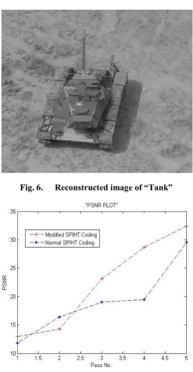
[image:4.595.317.544.70.227.2]For the operation we use gray scale image of “Tank” of size 512x512 as show in fig.4. In this image again first proposed modified SPIHT scheme was applied and performance parameters were measured and a PSNR vs. Pass No. graph was plotted. And then comparison between modified SPIHT compression and modified SPIHT method was done after that. A Modified Coding Scheme was applied over the “Tank” image for 5 passes and different parameters were recorded including the Execution Time, PSNR and MSE of the process. In table1 results of various parameters over 5 passes are shown.
[image:4.595.309.554.265.429.2]Fig. 4. Test image 2 “Tank” of size 512x512 Table 1. Parameter of Modified SPIHT Coding Scheme
on test image “Tank”.
Pass No.
parameters
1 2 3 4 5
Rate 128 64 32 16 8
PSNR(dB) 12.9408 14.244 23.15 28.67 32.39
MSE 3.30e+003 2.44e+003 314.5 88.37 37.49
bpp 0.0625 0.125 0.25 0.5 1
CR % 99.2188 98.4375 96.875 93.75 87.5
In this compression there are also some improved parameters (mainly PSNR, MSE and Execution Time) which can be noticed in table 1 and are quite remarkable.
[image:4.595.326.531.541.714.2]PSNR v/s Pass Number Plot for Test Image “Tank” for modified SPIHT method with normal SPIHT method. PSNR plot of a coding scheme for image “Tank” is shown in figure 7 which shows the improvement in the in reconstructed image after each pass of coding scheme up to five passes. The PSNR for 5 passes in dB is 32.39.
Fig. 6. Reconstructed image of “Tank”
Fig. 7. PSNR comparison between Modified SPIHT
coding and Normal SPIHT coding schemes.
In the proposed work, after applying Modified SPIHT coding scheme up to five passes, the overall performance parameters are recorded and compared by modified SPIHT coding method which is shown in table 2
[image:5.595.69.270.72.241.2]Same like previous results in this compression there are also some improved parameters (mainly PSNR, MSE and Execution Time) which can be noticed in table 2 and are quite remarkable
Table 2. Comparison b/w results obtained by modified SPIHT and modified SPIHT
Parameters Modified SPIHT Modified SPIHT
CR % 87.5% 87.5%
PSNR (dB) 32.3905 29.5727
MSE 37.499 71.7484
bpp 1 1
ET (Sec.) 17.6465 39.3315
If we compare the Modified SPIHT with the Modified SPIHT, we can notice that Modified SPIHT gives remarkable result. In this CR% and bpp are same with quite improved PSNR from 29.57dB to 32.39dB, reduced MSE from 71.7484 to 37.499 and reduced execution time of coding from 39.3315sec to 17.6465sec. which is our desired aim to be achieved.
6.
. CONCLUSIONIn this paper the original experiment and result was shown in above points. This paper has shown the flow of research that among two main process of compression i.e. transformation and coding, both of the processes has modified to improve the image compression. For this first lifting wavelet technique has been used for transformation and then coded by modified SPIHT.
In the experiment an image has been taken as mentioned above and in the image improved method has been used and PSNR values are recorded then it has been compared by a just one step back method which is also based on SPIHT method. After comparison it has been observed that although modified coding scheme gives the same amount of compression it does improve the PSNR when it is applied for more number of passes. In fig.7 we can clearly see that at starting point normal method is giving higher value than modified one but it is very low so as number of passes go on the PSNR of modified coding scheme is getting better more quickly than normal coding scheme. It has been observed that PSNR is being improved by 8% for image taken. Modified scheme is also giving very less value of MSE with great amount of improvement. Execution time of coding is the factor which is very important for transmitting data so it should be less to make the transmission fast. In modified scheme execution time is being improved by approximately 20 sec.
7.
REFERENCES
[1] Li Zhu and Yi_min Yang School of Mechanical Engineering and Automation Wuhan Textile University Wuhan, China; “Embeded Image Compression Using Differential Coding and Optimization Method”, 2011 [2] Ram, M. Elad, and I. Cohen, “Generalized tree-based
Wavelet transform”, IEEE Trans. on Signal Processing, Vol. 59, No. 9, pp. 4199–4209, September 2011
[3] S. Ktata and H. Mahjoubi Biophysics and Medical technology research laboratory at Higher Institute of Medica Is Technologies of the University of Tunis El Manar, 9 Rue Zouhair Essafi, 1006 Tunis, Tunisia; “A Zerotree Coding for Compression of ECG Signal Using EZW and SPIHT”, 2011.
[4] Vahid R. Dehkordi, Student Member, IEEE, Hoda Daou, Student Member, IEEE, and Fabrice Labeau, Senior Member, IEEE; “A Channel Differential EZW Coding Scheme for EEG Data Compression”, 2011.
[5] Zhijun Fang, Naixue Xiong, Member, IEEE, Laurence T. Yang, Member, IEEE, Xingming Sun, and Yan Yang; “Interpolation-Based Direction-Adaptive Lifting DWT and Modified SPIHT for Image Compression in Multimedia Communications”, 2011.
[image:5.595.48.288.607.746.2][7] S.P.Raja, Dr. A. Suruliandi “Performance Evaluation on EZW & WDR Image Compression Techniques”, IEEE Trans on ICCCCT, 2010.
[8] G. Sadashivappa, K.V.S. Ananda Babu, “Wavelet filters for image compression, an analytical study” ICGST-GVIP journal, volume (9), Issue (5), September 2009, ISSN: 1687-398X
[9] Emmanuel Christophe, Member, IEEE, Corinne Mailhes, Member, IEEE, and Pierre Duhamel, Fellow, IEEE; “Hyperspectral Image Compression: Adapting SPIHT and EZW to Anisotropic 3-D Wavelet Coding”, 2008.
[10]Lou jian yong,Lin jiang and Du xuewen “Application of Multilevel 2-D wavelet Transform in Image Compression”, IEEE Trans on Signal Processing 978-1-4244-3291-2, 2008