Programmable Logic Controllers
Richa Netto
Thadomal Shahani Engineering College, Mumbai University
Bandra, Mumbai - 400050 Maharashtra, India
Aditya Bagri
Thadomal Shahani Engineering College, Mumbai University
Bandra, Mumbai - 400050 Maharashtra, India
ABSTRACT
The analysis carried out in this technical paper highlights the concepts, working, advantages and practical applications of programmable logic controllers, along with a comparison with other control systems. A PLC aids in automation of a process by monitoring inputs and controlling outputs after making a decision on the basis of its program. It is commonly used for controlling many mechanical movements of heavy machinery and to control the voltage and frequency of power supplies. PLCs offer an array of advantages over other control systems, and have hence evolved as an important controller in industries these days owing to its large number of applications.
General Terms
Control SystemsKeywords
Automation, Ladder Logic, SCADA, Control Loop, Scan Cycle, EEPROM
1.
INTRODUCTION
In the past, humans were the main methods for controlling a system. Over the years, control engineering has evolved to include electricity in control systems. Previously, electromechanical relay based control systems were used. These systems obviated the use of switches for power on and power off actions. Elementary logic control decisions are predominantly undertaken by relays.
The advancement of economical computers has brought about a modern revolution, the Programmable Logic Controller (PLC). The PLC has its origins around the 1970’s in the automation and motor manufacturing industries.
2.
DESCRIPTION
Programmable Logic Controllers (PLCs), also referred to as programmable controllers, are a classification in computers. It is a device that performs discrete or continuous control logic in process plant or factory environments. PLCs are used in commercial and industrial applications. They have become popular since their inception in a wide variety of operations from boiler control to robot control.
The Allen-Bradley Company (Rockwell Automation) coined the term “Programmable Logic Controllers” as well as the corresponding acronym “PLC”. Both of these are therefore registered trademarks of the company. The National Electrical Manufacturers Association (NEMA) defines a programmable logic controller as:
“A digitally operating electronic apparatus which uses a programmable memory for the internal storage of instructions for implementing specific functions such as logic, sequencing,
timing, counting, and arithmetic to control, through digital or analog input/output modules, various types of machines or processes.”[1]
Programmable Logic Controllers are hardware and software engineered microcomputers, used to provide industrial control operations. A PLC audits inputs, makes decisions according to its program, and uses these decisions to administer outputs to automate a process or machine. The PLC is proficient in various tasks, including storage of instructions pertaining to sequencing, timing, counting, arithmetic, data manipulation and communication with the objective of controlling machines and processes.
3.
BASIC COMPONENTS OF A PLC
[image:1.595.314.544.398.554.2]The basic components of a PLC are as follows:
Figure 1: Block diagram of a PLC
3.1
I/O Modules
I/O modules physically connect to field devices. Since there are different types of input and output devices, the process determines the type of input or output module selected, digital or analog.
Inputs give the controller real-time status of variables in the form of real world signals. These variables can be analog, register or discrete. Typical analog inputs can be from thermocouples, RTDs, flow, pressure, and temperature transmitters. These inputs are transmitted over the I/O bus to the central processor unit after being converted into digital data. The input module is entrusted with the operation of converting electrical signals flowing in from input field devices like push buttons to electrical signals that the PLC can understand.[2] Examples of input modules include limit switches, proximity switches and push buttons.
Power Supply
Memory
Input Output
Programming Device
CPUSignals to solenoids, motors etc. Signals
Figure 2: Input Module
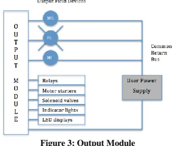
[image:2.595.77.255.348.497.2]The output module converts the signals containing instructions of the desired status of outputs into real world outputs after they have been transmitted over the I/O bus to the module. There are three categories of outputs: discrete, register and analog. Information flowing out from the PLC is again converted into electrical signals that can be interpreted by the output field devices, by the output module. Examples of these output devices are motor starters or hydraulic solenoid valves.
Figure 3: Output Module
3.2
Processor
The processor is the intellect behind the PLC. It is similar in construction to the microprocessor used in personal computers. The Central Processor Unit (CPU) performs tasks such as self-diagnostics, memory management, data handling execution, scanning, peripheral and external device communications, resource sharing, program execution and I/O bus traffic control.[3]
Execution of various logic and sequencing functions is carried out by the CPU, which operates on the PLC inputs to determine the appropriate output signals. Operations such as adding, subtracting, multiplying, dividing and comparing are performed by the Arithmetic Logic Unit which is usually a part of the CPU (but sometimes it is separate).
Figure 4: Central Processing Unit
The working of a processor is as follows: The signal to the input modules is transmitted by the machine or process input elements. The input modules then generate a logic signal that is sent to the CPU. When it receives instructions from the memory and the feedback on the status of the I/O devices, the CPU produces commands for the output devices. These commands control the devices on a machine or a process.[4] Typical loads to be controlled are devices such as solenoid valves, indicator lamps, relay coils and motor starters.
3.3
Power Supply
PLCs and their constituting modules are equipped with power generated from a power supply. The power supply converts power line voltages into those required by the solid-state components. It may be integral or separately mounted which provides the isolation necessary to protect solid-state components from high-voltage line spikes.The power supply also provides the heat dissipation required for the plant floor operation. It drives the Central Processor Unit, I/O logic signals, memory unit and some peripheral devices.[5] The expansion of I/O has lead to increased power requirement of some PLCs. Hence, they are furnished with additional power supplies.
3.4
Memory Unit
The memory unit of a PLC is the registry where the programs are stored. The fundamental unit of memory is the word. Words are made up of bits. A bit is a single piece of data. It contains information on only two states (ON/OFF or YES/NO). Longer words contain more information within. Programs are combination of words that produce control logic.
Memory can be volatile or non-volatile. Volatile memory is undesirable as is results in loss of data when power is removed. Battery backup is usually a feature of volatile memory systems. On the other hand, power outages do not result in change of state of the non-volatile memory. Therefore, it is administered in cases where it is expected that the transportation time to the job site will be long or extended power outages will be frequent.
Memory is of three types: Read Only Memory (ROM), Read/Write Memory (R/W) and Random-Access Memory (RAM).[6] Another type of memory is the electrically alterable
programmable read only memory (EAPROM).
3.5
Network Interface
PLCs are capable of communicating with other devices like computers running programming software, a terminal that lets an operator enter commands into the PLC, or an I/O that is located in a remote location from the PLC. This communication is carried out through a network interface. There are two ways in which the network interface can be a part of the PLC: it can be built directly into the PLC or it can appear as a plug on the front of the PLC.[7]
3.6
Programming Units
[image:2.595.52.278.663.736.2]Programming devices vary greatly in size, ranging from small units that are hand-held to large, astute CRT-based units with the ability to document, compute I/O status and work in both online as well as offline modes.[8] A personal computer is the most commonly used programming device.
PLCs are configured using the software that runs on personal computers. Different products may require different programming software. Software allows programs to be written in several different languages and allows users to create, edit, document, store and troubleshoot programs.
4.
PROGRAMMING A PLC
PLCs are programmed in two ways. One is to directly connect the PLC to a computer and the other is to make use of a programming panel. Logical commands are used to program the PLC in both scenarios. The panels used in programming a PLC differ greatly in their intricacies, ranging from simple keypads to hand-held computers with a screen for graphics. The programming software is operated on computers with graphics, simulators, diagnostics and auditing. After the software programmer develops the program, it is tested and then sent to the PLC. This can be done using magnetic tapes, compact disks, and communication links. However, the most common method for the transfer of a program to the PLC is by using a chip to which the program is written, commonly known as an EEPROM. After this, the chip is plugged into the PLC. The memory can be erased by exposure to UV light and reused but it cannot be overwritten.[6]
The PROGRAM mode of the processor is used when the program has to be entered into the PLC. The instructions are entered sequentially, one at a time with the help of the programming device. The controller is made to work in the RUN state (or operating cycle) when the program has to be carried out. As a consequence of each operating cycle, the controller reviews the status of the input devices, executes the program that has been entered and alters the outputs accordingly.
5.
WORKING OF A PLC
[image:3.595.359.515.74.219.2]The main components of a PLC are input modules, a Central Processing Unit (CPU), and output modules. A variety of digital or analog signals are accepted from various field devices by the input module. They are then converted into a logic signal that the CPU can use. The program instructions stored in the memory form the basis upon which the CPU makes decisions. These decisions eventually result in execution of the control instructions as required by the program. Control instructions from the CPU are converted into a digital or analog signal by the output module. This signal can be used to control various field devices. A PLC works by scrutinizing a program, instruction by instruction, continuously. This process is also known as scanning. One scan time is defined as the time taken to complete the three steps. The control loop is a continuous cycle of the PLC reading inputs, solving the ladder logic, and then changing the outputs.[9]
Figure 5: Scan Cycle
Control circuits have been conventionally described using ladder diagrams. Ladder diagrams consist of rungs; each one of these is a program statement. A program statement is basically a condition, or a set of conditions (input). Each one of these conditions has an action (output) associated with them that is executed if the condition is satisfied. Elementary logic operators like AND, OR and NOT are used to perform logical operations required by the PLC. They combine the instructions in the program statement (present on a PLC rung) thus making the result of each run either true or false (1 or 0).[10]
The instructions entered using a programming device determine what action will be performed by the PLC for a particular input. A device acting as an operator interface displays process information and provides for the addition of new process parameters to increase or decrease level of control.
6.
COMPARISON OF PLCs WITH
OTHER CONTROL SYSTEMS
PLCs are predominantly used in industrial processes where the development and maintenance costs of the automation system exceeds the total cost of automation and where it might be necessary to alter the system during its operational life, examples of these include motion and positioning control. Also, they cater to applications where the system required is highly customized. However, PLCs lack the capability requisite of highly complex algorithmic processes, like in the chemical industry.
Different techniques entailing the use of microcontrollers, relay systems, minicomputers, solid-state controls, digital logic control systems and electronic continuous control systems, among many others, are preferred for high volume or simple fixed automation tasks.
Relays can construct complicated control systems by linking an array of logic components. On the other hand, a typical relay system has hundreds of switching contacts, presenting the design engineer with a daunting task especially when the control function of a panel has to be changed, eventually resulting in complete re-wiring of the system. They do not provide the troubleshooting flexibility offered by modern programmable control systems. Relays also take up more space and require regular maintenance.[11] In addition, the high cost, low speed and lack of reliability has resulted in the replacement of relay systems by modern substitutes. Relays remain optimal for reconstruction of small control signals to higher current or higher voltage driving signals. This explains their comprehensive usage as output devices for other control systems.
CHECK INPUT STATUS
EXECUTE PROGRAM
Table 1: Comparison of PLCs with other Control System[3]
Parameters Relays Solid-State Controls
Microprocessor Minicomputer Digital Logic PLCs
Hardware cost Low Equal Low High Average (can be
high in small quantities)
Depends on number of controls
Versatility Low Low Yes Yes Yes
Troubleshooting and maintainability
Poor Poor Poor Poor Poor if IC’s are
soldered
Good
Computer compatible
No No Yes Yes Yes Yes
Arithmetic capability No No Yes Yes Yes Yes
Programming cost (Wiring) High
(Wiring) High High High Low Low
Reusable No No Yes Yes Yes
Space required Largest Large Small Ok Fairly compact Small
Operating speed Slow Faster than electro- mechanical relays
Fairly fast Fairly fast Fairly fast Fast
PLCs have a logic called PID (proportional, integral, derivative) controller. Usually, PLCs are constructed with very less analog loops; processes that require a large number of loops are based on distributed control system (DCS). With time, as the power of the PLC increases, the gap between applications of PLCs and DCSs has lessened greatly.[12] Digital Logic Control Systems use logic gates to process information (exclusively encompassing binary signals). Logic gates run at much higher speeds, cause lesser power consumption and occupy considerably lesser space than a corresponding relay circuit. Nonetheless, they are incapable of switching to higher power driving signals.
Operational amplifiers, a part of Electronic Continuous Control Systems involve the performance of mathematical operations like integration, differentiation, etc. They were utilized in the field of continuous control and lead to the simplification of complex control functions with discrete electronic systems. Largely built on linear integrated circuits, analog control is efficient with high speed. The fine-tuning of such systems during designing coupled with their fixed nature continues to cause hindrances.
A design based on microcontrollers is pertinent in systems where hundreds or thousands of units are to be produced where the end-user would not have to alter the control and the development costs are large. They can be a part of sequence and continuous control systems. Both microprocessors and microcontrollers simplify connection requirements due to their small size, making them easily locatable at the point of final control.
7.
ADVANTAGES
To implement changes in control logic of a PLC no rewiring is required which saves considerable time. PLCs can carry out complex functions such as generation of time relays, counting, comparing, arithmetic operations, etc. Increased technology
makes it possible to condense more functions into smaller and less expensive packages. The cost of a PLC is recovered in a short period, hence making it highly economical.
When changes are made to the program circuit or sequence design or when a programming fault has to be revised in the ladder diagram, the necessary amendments can be made easily by just typing it in using a keyboard. This results in faster, and at the same time, convenient troubleshooting.
If the need arises, an instantaneous printout of the original PLC circuit can be made available effortlessly, hence making documentation very efficient. The PLC prints out the actual circuit in operation at a given moment.[7] There is no need to look for the blueprint of the circuit in remote files. Due to their solid-state nature, PLCs are extremely compact and much more reliable when compared with hardwired controllers. Ergo, the costs of maintaining PLC based control systems are low.[13]
A PLC can form networks to communicate with other devices like controllers. They can be correlated to perform operations such as supervisory control, data gathering, monitoring devices and process parameters, and downloading and uploading of programs. PLCs consume only 10% of the power consumed by an equivalent relay logic controller and hence also save energy.
8.
DISADVANTAGES
The stop button is employed to disconnect a circuit in relay system; the system stops if the power fails. The PLC can be programmed to perform this function; although, in certain programs, to stop a device, one may have to apply an input voltage. Being fail-safe is not one of the features of this system.
features of PLC that is reprogramming would not be required since their operational sequence is very rarely altered.[7] In a process, the environment may experience high heat, vibration, and direct contact with electrical appliances within the PLC. Such events continuously disrupt the performance of the PLC. In addition, professional expertise is required to replace the previously used control system employing relay ladder by a PLC computer concept as the technology is comparatively new.
9.
APPLICATIONS
PLC is used as a widespread controller that has numerous applications. With the program installed in its memory, it provides the user with a simple method of changing, extending and optimizing control processes. In a PLC, input signals are interconnected in accordance with a specified program. If “true”, the PLC jumps to the resultant output. The mathematical base for the working is Boolean algebra that acknowledges only two states for one variable: 0 and 1. Modern PLCs can perform timer and counter functions, memory setting and resetting and mathematical computing operations.[14] Industries have a variety of production tasks that are highly repetitive in nature. In spite of each stage being repetitive and monotonous, it requires careful attention of the operator to ensure effective production. Whenever sequential control and automation is required, PLCs are best suited to accomplish the task.
Supervisory Control and Data Acquisition (SCADA) is a form of widespread industrial control structure that incorporates numerous sites and large distances. Here, PLCs are of use in industrial processes like: manufacturing, production, power generation, fabrication and refining. Infrastructure processes requiring PLCs are: water treatment and distribution, waste water collection and treatment, oil and gas pipelines, electric power transmission and distribution, wind farms, civil defence siren systems and large communication systems.
PLCs find applications in the tire industry, steel factories, food and beverages industry, pulp factory, petrochemical industry, mining, power, continuous bottle-filling system, 3 stage air conditioning system, speed control of DC motor and other similar sequential task as well as process control.[15]
10.
CONCLUSION
The requirement for higher quality and reliability in control techniques has stemmed from a constant demand for better and more efficient and process machinery. Smart, condensed solid-state electronic devices have made it feasible to offer control systems that can ease maintenance, reduce downtime and enhance productivity by a large amount. Flexible and proficient working has been offered to the user by programmable logic controllers. Starting out as a replacement for relays, various math and logic manipulations were gradually added to the PLC along with the incorporation of smaller cases, faster CPUs, networking and various Internet technologies. PLCs continue to develop and have become vital to a great extent of automation processes. New values make an addition to their potential incessantly.
11.
ACKNOWLEDGEMENT
This technical paper has been done under the support and guidance of Mr. G.K. Dey, Manager (Engineering Services, Instrumentation) at Godrej Industries Limited.
12.
REFERENCES
[1] W. Bolton, Programmable Logic Controllers, Fifth Edition, Newnes, 2009.
[2] Clarence T. Jones, Programmable Logic Controllers: The Complete Guide to the Technology, Patrick-Turner, 1996.
[3] W.N. Clare, G. T. Kaplan, D. R. Saldon, A. C. Wiktorowicz, R. A. Gilbert, C. W. Wendt, Process Control and Optimization Volume II.
[4] James A. Rehg, Glenn J. Sartori, Programmable Logic Controllers, Prentice Hall Higher Education, 2009.
[5] S.K. Singh, Industrial Instrumentation and Control, Second Edition, Tata McGraw-Hill, 2007.
[6] D. J. Dunn, Selection and Application of Programmable Logic Controllers.
[7] Dr. D. J. Jackson, Programmable Logic Controllers – Introduction to PLCs.
[8] Sadegh Vosough, Amir Vosough, PLC and its Applications, International Journal of Multidisciplinary Sciences and Engineering, Vol. 2, No. 8, November 2011.
[9] Greg P. Zimmerman, Programmable Logic Controllers and Ladder Logic, April 2008.
[10] Albert Falcione, Bruce H. Krogh, Design Recovery for Relay Ladder Logic, IEEE Control Systems, First IEEE Conference on Control Applications, September 1992.
[11] Gregory K. McMillan, Douglas M. Considine (ed), Process/Industrial Instruments and Controls Handbook Fifth Edition, McGraw-Hill, 1999.
[12] Sanjeev Gupta, S C Sharma, Selection and Application of Advance Control Systems: PLC, DCS and PC-based system, Journal of Scientific & Industrial Research, Vol. 64, April 2005, pp. 249-255.
[13] Prof. Jose A. Rodriguez Mondejar, Programmable Logic Controller, UPCO ICAI Departmento de Electronica y Automatica.
[14] John R. Hackworth, Frederick D. Hackworth, Jr., Programmable Logic Controllers: Programming Methods and Applications.


![Table 1: Comparison of PLCs with other Control System[3]](https://thumb-us.123doks.com/thumbv2/123dok_us/8066494.778020/4.595.47.545.87.358/table-comparison-plcs-control.webp)
