Implementation of Wavelet Based Robust Differential
1Control for Electric Vehicle Application
23
J.L. Febin Daya, P.Sanjeevikumar, Senior Member, IEEE, Frede Blaabjerg, Fellow, IEEE, 4
Patrick W.Wheeler, Senior Member, IEEE, Joseph Olorunfemi Ojo, fellow, IEEE 5
6 7
Abstract: This research article presents the modeling and simulation of electronic differential, employing a 8
novel wavelet controller for two brushless DC motors. The proposed controller uses discrete wavelet 9
transform to decompose the error between actual and reference speed. Error signal which is actually given 10
by the electronic differential based on throttle and steering angle is decomposed into frequency components. 11
Numerical simulation results are provided for both wavelet and PID controllers. In comparison the proposed 12
wavelet control technique provides greater stability and ensures smooth control of the two back driving 13
wheels. 14
15
Keywords: Brushless dc motor, Wavelet transforms, Fuzzy logic, PID controllers, Indirect field oriented 16
control, Electrical Vehicles. 17
18
Introduction:Increasing demand on automobiles, the need for vehicle safety on the road too becomes a 19
major concern. Differential system plays an important role to prevent slipping of vehicles on curved roads. 20
Mechanical differentials are heavy and bulky, not suitable for electric vehicles. Electronic differential 21
constitutes a technological advance in electric vehicle design, enabling better stability and control of the 22
vehicle on curved roads. Neighbourhood Electric Vehicles (NEV) is at present the best solution for personal 23
transportation to keep air quality and traffic problems in check. NEV implementation with two independent 24
wheel drives using induction motors, where the current and speed controllers of which were Proportional-25
Integral-Derivate (PID) compensators [1]. But PID controller is not robust, need to be tuned for its gain 26
parameters at each operating conditions. Recently, PID controllers are replaced by discrete wavelet 27
transform, thanks to the technology for its robustness [2-8]. Wavelet transforms found applications in ac 28
(ac-dc), shown better performance with experimental implementation than standard PWM techniques [2-4]. 30
Further, wavelet transform techniques are extended to ac motor applications [5] in particular to electrical 31
vehicles (EV). Fuzzy-neural control wavelet algorithms are implemented for steering control of electrical 32
vehicles (ac motor drives) [6], also applied successfully for energy management system in plug-in hybrid 33
electric vehicles (HEV) [7]. Exploiting the advantages of wavelet technology, this work involved the 34
modelling and simulation of an electronic differential with a novel wavelet controller for two brushless DC 35
motors, which is yet not proposed by the research articles. 36
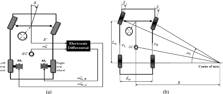
[image:2.612.79.551.215.415.2](a) (b)
Fig. 1. (a) Proposed electronic differential structure, (b)Model of the vehicle driven during a curve. 37
38
System Modelling of Electronic Differential: Fig. 1(a) depicts the proposed electronic differential 39
structure, where the left and rights wheels are controlled using two separate motors. BLDC motors are 40
preferred due to high efficiency, high torque density, silent operation and low maintenance favours the 41
electric vehicle application. Two inputs the steering angle and throttle position collectively decide the speeds 42
of the right and the left wheel in order to prevent the vehicle from slipping. For a right turn, the differential 43
has to maintain a higher speed at the left wheel than the right wheel to prevent the tyres from losing traction 44
while turning. Fig. 1(b) depicts the vehicle during a turn. Lw is the wheel base, δ is the turning angle, dw is
45
the track width, R is the radius of the turn and ωR and ωL represent the angular speeds of the left and the right
46
wheel respectively. The linear speed of each wheel can be represented as a function of the vehicle speed and 47
& (1)
The relation between the radius of the turn and steering angle and wheel base is: 49
(2)
Substituting (2) in (1), we get angular speed of each wheel as: 50
& (3)
The difference between the angular speeds of the wheel drives can be expressed as: 51
! " (4)
The sign of the steering angle indicates the direction of the turn δ> 0 = Turn Right, δ< 0 = Turn left, δ = 0 = 52
Straight Ahead. When the steering input is given by the driver, the electronic differential immediately acts 53
by reducing the speed of the inner wheel and increasing the speed of the outer wheel. The driving speeds of 54
the wheels are: 55
# $% & # $% (5)
56
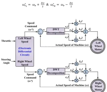
Fig. 2. Schematic circuit of proposed novel wavelet based indirect field oriented controller (IFOC) for
electronic differential of two brush-less dc (BLDC) motors. 57
[image:3.612.129.487.363.671.2]Discrete Wavelet Controller: Fig. 2 shows the overall schematic of the wavelet based speed controller of 59
two brushless DC motor drives. The throttle position and the steering angle were given as input for the 60
electronic differential which generates the desired speed for the left motor and the right motor. The error 61
detector compares the desired speed and actual speed and generates the error speed which will be used by 62
the wavelet controllers to generate the control signal for the drive system. The control component generated 63
by the wavelet controllers are used to drive the two indirect field oriented control (IFOC) BLDC motor 64
(two). 65
Resolution of DWT begins when a discrete signal &' ( of length N is passed through a high pass filter 66
resulting in an impulse response )' ( and through a low pass filter resulting in an impulse g' (. One level of 67
DWT is constituted by the outputs of high and low pass filter can be mathematically expressed as [5, 8-9]: 68
"*' ( ∑- *&',()' ,(
./0 ; *' ( ∑- *./0&',(1' ,( (6)
where, "*' ( and *' ( are the outputs of the high and low pass filters. After this again the output from the 69
low pass filter is down sampled by two and again passed through a low and a high pass filter resembling the 70
ones in the first level and expressed as (second level of decomposition) [5, 8]: 71
" ' ( 2 *',()' ,(
-/ *
./0
; ' ( 2 *',(1' ,(
-/ *
./0
(7)
Several types of wavelet filters available, the minimum description length (MDL) criterion select the best 72
and mathematically expressed as: 73
56 7,, 9 :; <32 ,?@1A A2 log EFGH G7.9FE I,
0 K , K A; 1 K K 5
(8)
where, GH M N denotes a vector of the wavelet transformed coefficients of the signal f using wavelet 74
filters (n). G7.9 OPGH OP7M N9 denotes a vector that contains k non-zero elements. The threshold 75
parameter OP keeps k number of the largest elements of the vector GH constant and sets all other elements to 76
zero. N and M denote the length of the signal and the number of wavelet filters, respectively. The entropy 77
Q7&9 of a signal &' ( of length N is defined as: 78
Q7&9 2 |&7 9| log |&7 9|
- *
/0
(9)
For determining the optimal levels of decomposition, the entropy is evaluated at each level. For a new 79
level j, if: 80
Q7&9S T Q7&9S * (10)
Two levels of decomposition sufficient for effective representation of the error signal. The components 81
(low/high frequency components) were scaled by their respective gains and then added together to generate 82
the control signal u: 83
U , V , V W , XV X , XV X (11)
where, gains , , , , … , , X are used to tune the high and medium frequency components of the error 84
signal (V , V , … , V X). Gain , X is used to tune the low frequency components of the error signal 7V X9
85
and N is the number of decomposition levels. 86
Numerical Simulation Results: To illustrate the wavelet controller performances, the parameters of the two 87
identical BLDC are taken with 2hp, 460V, 60Hz, 1750rpm rating, PWM sampling time of 0.5µsec. First 88
investigation test typically designed and framed for straight road followed by a curved road on the right 89
(clockwise) at a constant speed of 60km/hr. During the turn, the speeds of the wheels change according to 90
the command of the electronic differential. For this purposes, the amplitudes and respective time of the 91
speed and steering angle inputs are as given by Table I. 92
TABLE I. INVESTIGATION DESIGN CRITERION FOR TEST-1. 93
Time Vector (Sec) Amplitude(km/hr) and Angle (deg) Speed Input [0 0.2 0.3] [60 60 60]
Steering Angle Input [0 0.2 0.3] [0° 30° 30°] 94
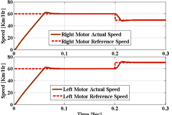
It is observed from the test results of Fig.3 (PID controller) and Fig.4 (Wavelet controller), that wavelet 95
controller based electronic differential offers smooth performance compared to conventional PID Controller. 96
Moreover, the wavelet based electronic differential offers lesser overshoot (60.09km/hr) and settles quickly 97
(0.05sec) when compared to PID controller electronic differential (63km/hr, 0.09sec). Therefore, the left and 98
100
Fig. 3. Numerical simulation output response behaviour of BLDC motors by the PID controller 101
(Investigation Test-1). Top: Motor 1, Bottom: Motor 2. 102
103
[image:6.612.160.454.277.472.2]104
Fig. 4. Numerical simulation output response behaviour of BLDC motors by the wavelet controller 105
(Investigation Test-1). Top: Motor 1, Bottom: Motor 2. 106
107
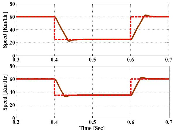
Second investigation test typically designed for straight road with a constant speed of 60km/hr., followed by 108
a right turn (300) at 30km/hr.; followed by a straight road at a constant speed of 60km/hr as given by Table 109
II. 110
TABLE II. INVESTIGATION DESIGN CRITERION FOR TEST-2. 111
Time Vector (Sec) Amplitude(km/hr) and Angle (Deg) Speed Input [ 0.3 0.4 0.6 0.7 ] [60 30 60 60]
Fig. 5 (PID controller) and Fig. 6 (Wavelet controller) shows the response behaviour of two BLDC motor. 113
It observed the peak overshoot with the PID controller is 63km/hr whereas with the wavelet controller, it is 114
60.09km/hr. Where the desired speed though is 60 km/hr. and obtained settling time with the PID controller 115
is 0.09sec whereas with the wavelet controller, it is 0.05sec. 116
117
[image:7.612.157.452.161.384.2]118
Fig. 5. Numerical simulation output response behaviour of BLDC motors by the PID controller 119
(Investigation Test-2). Top: Motor 1, Bottom: Motor 2. 120
121
[image:7.612.164.448.428.619.2]122
Fig. 6. Numerical simulation output response behaviour of BLDC motors by the wavelet controller 123
(Investigation Test-2). Top: Motor 1, Bottom: Motor 2. 124
125 126
Finally, the performances by wavelet controller are robust due to its discreet transform provides 127
responsible for controller functioning i.e lesser this gain value, the lesser the peak overshoot. But the 129
detailed coefficients ( , , ... ,,X ) are the high frequency components responsible for controlling the 130
noise signals and doesn’t affect the output speed performances under ideal noise free condition [9]. 131
132
Conclusion: This article presented an electronic differential control for electrical vehicle utilizing a novel 133
wavelet based speed controller. The proposed electric vehicle with two BLDC systems was implemented in 134
numerical simulation software and the performances are compared with PID controller. Further, it has been 135
confirmed that wavelet controller provides smooth control due to decreased peak overshoot and reduced 136
settling time. Hence, the proposed wavelet controller performances are superior and suits electrical vehicle 137
application in particular to curved roads transportation. 138
Further, real time implementation of proposed complete two motor ac drives system with wavelet controller 139
using digital signal processor (dsp) is actually under construction. This research article keeps further 140
investigations under studies, in particular with single wavelet IFOC controller algorithm for multi BLDC 141
motors (more than two motors) driven with single and/or multiple inverter drive system for future 142
publications. 143
144
References
145
[1] A. Draou, “Electronic differential speed control for two in-wheels motors drive vehicle”, in Proc. IEEE 146
4th Intl. Conf. Power Engg. Energy Elect. Drives, IEEE-POWERENG’13, Istanbul, Turkey, pp. 764-147
769, 13-17 May 2013. 148
[2] S.A.Saleh, M.Azizur Rahman, “Experimental Performances of the Single-Phase Wavelet-Modulated 149
Inverter”, in IEEE Trans. on Power Electron., vol. 36, no. 9, pp. 2650-2661, Sept. 2011. 150
[3] S.A.Saleh, “The Implementation and Performance Evaluation of 3Ф VS Wavelet Modulated AC-DC 151
Converters”, in IEEE Trans. on Power Electron., vol. 28, no. 3, pp. 1096-1106, March 2013. 152
[4] D. Gonzalez, J. T. Bialasiewicz, J. Balcells, J. Gago, “Wavelet based performance evaluation of power 153
converters operating with modulated switching frequency”, in IEEE Trans. Ind. Electron., vol. 55, no. 154
[5] M.A.S.K.Khan, M.A.Rahman, “Implementation of a new wavelet controller for interior permanent 156
magnet motor drives”, in IEEE Trans. Ind. Appl., vo. 44, pp. 1957–1965, 2008. 157
[6] Y-C.Hung, F-J.Lin, J-C.Hwang, J-K.Chang, K-C,Ruan, “Wavelet Fuzzy Neural Network With 158
Asymmetric Membership Function Controller for Electric Power Steering System via Improved 159
Differential Evolution”, in IEEE Trans. on Power Electron., vol. 38, no. 4, pp. 2350-2362, April 2014. 160
[7] C.Sun, S.J.Moura, X.Hu, J.K.Hedrick, F.Sun, “Dynamic Traffic Feedback Data Enabled Energy 161
Management in Plug-in Hybrid Electric Vehicles”, in IEEE Trans. on Power Electron., vol. 23, no. 3, 162
pp. 1075-1086 May 2015. 163
[8] S. G. Mallat, “A theory for multi-resolution signal decomposition: The wavelet representation,” in 164
IEEE Trans. Pattern Anal. Mach. Intell., vol. 11, no. 7, pp. 674–693, Jul. 1989. 165
[9] L. Coppola, L. Qian, S. Buso, D. Boroyevich, A. Bell, “Wavelet transform as an alternative to the short-166
time Fourier transform for the study of conducted noise in power electronics”, in IEEE Trans. Ind. 167
Electron., vol. 55, no. 2, pp. 880–887, Feb. 2008. 168