Department of Civil Engineering, University of Nottingham, University Park, NG7 2RD Nottingham, United Kingdom b
Department of Civil Engineering, University of Khartoum, P.O. Box 321, 11111 Khartoum, Sudan cDICEA, Università Politecnica delle Marche, Via Brecce Bianche, 60131 Ancona, Italy
d
SAAD, University of Camerino, Viale della Rimembranza, 63100 Ascoli Piceno, Italy
a r t i c l e i n f o
Article history: Received 4 April 2016
Received in revised form 10 August 2016 Accepted 16 September 2016
Keywords: Tunnelling Pile
Soil-structure interaction Building response
a b s t r a c t
In urban areas, engineers often need to assess tunnelling-induced displacements of piled structures and the resulting potential for damage. This paper presents an elastic study of tunnel-pile-structure interac-tion through Winkler-based Two-Stage Analysis Methods (TSAMs), focusing on structural displacements resulting from tunnel excavation beneath piled frames or simple equivalent beams. Comparison of results with 3D finite element analyses shows that the simple TSAM models are able to provide a good assess-ment of tunnelling-induced building displaceassess-ments. Parametric analyses highlight the role of tunnel-pile interaction and the superstructure (stiffness, configuration, and pile-structure connections) in the global response of the tunnel-soil-building system. In particular, the effect that key parameters have on deflec-tion ratios and horizontal strains are investigated. Results illustrate how piled foundadeflec-tions increase the risk of structural damage compared to shallow foundations, whereas structural stiffness can reduce building deformations. Flexural deformations are predominately induced by tunnel excavations beneath piles whereas horizontal strains at the ground level are negligible when a continuous foundation is included. Furthermore, it is illustrated that results based on buildings modelled as equivalent beams can differ considerably compared to when they are modelled as framed structures. Simple design charts are provided to estimate horizontal strains and deflection ratio modification factors based on newly defined relative axial and bending stiffness parameters which account for the presence of the piles.
Ó2016 The Authors. Published by Elsevier Ltd. This is an open access article under the CC BY license (http:// creativecommons.org/licenses/by/4.0/).
1. Introduction
In urban areas, the increasing demand for infrastructure and development of services has resulted in tunnel construction and deep excavations taking place in close proximity to buried infras-tructure and building foundations. To avoid possible damage to structures, engineers need to be able to accurately assess excavation-induced deformations of the buildings. However, although various studies have considered the effect of excavations on either a building with shallow foundations or piles connected by a rigid cap, the understanding of how the tunnel-pile interaction affects the response of buildings is still not well understood.
Various studies have considered the case of tunnel construction beneath buildings with shallow foundations. It has been recog-nised that the building stiffness should be taken into account in the assessment of tunnel-structure interaction since it generally
tends to decrease the structural distortions and risk of damage with respect to the greenfield case (Franzius et al., 2006; Dimmock and Mair, 2008; Maleki et al., 2011; Farrell et al., 2014; Giardina et al., 2015). On the other hand, the tunnel-single pile and pile group interaction problems have been widely analysed using field trials, physical modelling, and numerical simulations, leading to some confidence in the assessment of pile group dis-placements (Jacobsz et al., 2004; Kaalberg et al., 2005; Selemetas, 2005; Devriendt and Williamson, 2011; Marshall and Mair, 2011; Dias and Bezuijen, 2015), internal forces (Kitiyodom et al., 2005; Huang et al., 2009; Ng et al., 2012; Soomro et al., 2015), and pile failure due to tunnel excavation (Marshall and Haji, 2015). How-ever, as indicated byMair and Williamson (2014), studies have focused predominately on tunnelling adjacent to piles, for which the induced building distortions are expected to be minimal. In these cases, tunnelling mainly causes lateral bending in piles rather than settlements along the pile axis. In contrast, tunnelling beneath piles induces vertical pile movements, which leads to structural deformations. Moreover, it is important to note that only
http://dx.doi.org/10.1016/j.tust.2016.09.008
0886-7798/Ó2016 The Authors. Published by Elsevier Ltd.
This is an open access article under the CC BY license (http://creativecommons.org/licenses/by/4.0/).
⇑Corresponding author.
a few studies have considered the effects of structural configura-tion on building deformaconfigura-tions induced by excavaconfigura-tions. Goh and Mair (2014)highlighted the importance of structural configuration in the global interaction based on an extensive set of numerical analyses which evaluated the response of framed buildings to deep excavations.Fargnoli et al. (2015) suggested that the use of an equivalent plate and beam model for the superstructure may lead to an erroneous evaluation of the structural response to tunnelling-induced movements. The work ofLosacco et al. (2014)suggested that, in order to obtain satisfactory results, more advanced simpli-fied structural models of the building, rather than a simple beam/-plate, could be incorporated into the global interaction analysis.
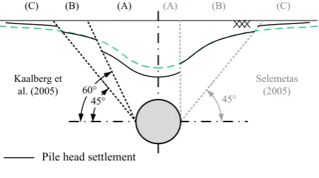
In a preliminary risk assessment of building damage caused by tunnelling, it is important to be able to predict, with reasonable simplicity and reliability, the induced structural deformations. However, for tunnelling beneath buildings on piled foundations, there is a limited amount of information and guidance available to inform such a risk assessment. In practice, engineers typically evaluate the tunnelling-induced deformations empirically, assum-ing that pile heads settle accordassum-ing to a subsurface greenfield set-tlement profile. The depth of the selected setset-tlement trough is usually taken at some distance between the surface and the pile tip in order to account for the piles being dragged down by subsur-face soil movements (Devriendt and Williamson, 2011). For tun-nels, several relationships between surface greenfield soil displacements and pile head settlements have been proposed depending on pile tip position. For instance, Kaalberg et al. (2005) and Selemetas (2005) suggested three zones where pile head settlements may be larger than (zone A), equal to (zone B) or smaller than (zone C) the greenfield surface settlements (see Fig. 1). These also agree qualitatively with results obtained by other researchers who used centrifuge testing to study the prob-lem (Jacobsz et al., 2004; Marshall and Mair, 2011).
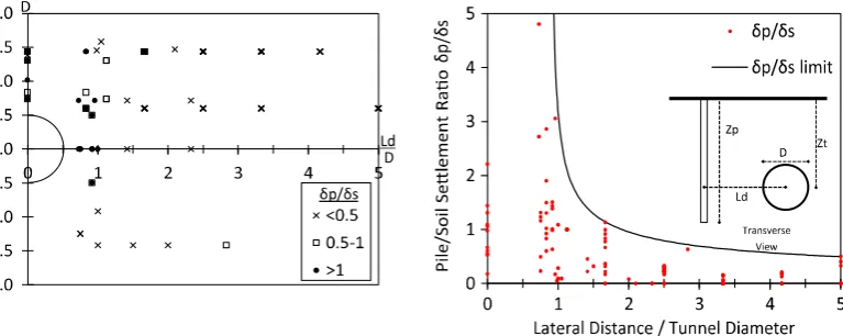
However, despite the general agreement, a comparison of previ-ous studies carried out byDias and Bezuijen (2015)demonstrated that the relationship between pile head and greenfield surface set-tlements is not a unique function of the relative tunnel-pile tip position; it also depends on working loads, tunnel volume loss, and distribution of working load between pile base and shaft. As shown inFig. 2,Dias and Bezuijen (2015)indicated that the regions A-B-C defining the relative pile/surface settlements do not capture the full complexity of the problem. The authors suggested an upper limit of the normalised pile head settlement depending on the nor-malised horizontal pile offset to the tunnel centreline. However, use of this upper limit would lead to an over-conservative assess-ment of tunnelling-induced deformation in piled buildings.
The previous studies indicate that piles with their tips directly above the tunnel (i.e. within a horizontal offset of one tunnel
radius from the tunnel axis) are likely to settle more than the sur-face, whereas piles outside this area generally settle less than the surface. This causes a narrowing of the pile head settlement profile with respect to the greenfield surface settlement trough, leading to an increased potential for building damage. Moreover, assessing tunnelling-induced deformations in buildings using a tunnel-pile interaction analysis (i.e. assuming that the building follows the set-tlement curve obtained from a tunnel-pile or tunnel-pile group analysis) does not allow inclusion of the influence of the building on the global interaction; this may be overly conservative in the cases of relatively stiff structures, as illustrated by a case study reported byGoh and Mair (2014).
In the first part of this paper, the complete tunnel-pile-structure interaction is investigated through a Winkler-based Two-Stage Analysis Method (TSAM), focusing on structural displacements that result from the tunnel excavation. Since displacements are damage related quantities, their prediction can be used to evaluate building serviceability state. The TSAM method is able to capture the main interaction mechanisms and the effects of structural configuration on the global response of the system to tunnelling. In the second part of the paper, effects of structure stiffness on the building deformations, both axial and flexural, are investigated, with emphasis on the role played by the piled foundations. Two simple design charts for evaluating the piled building deflection ratios and horizontal strains are proposed.
2. Background
2.1. Two-stage analysis method (TSAM)
Soil-structure interaction systems are characteristically com-plex due to the effects of interfaces, soil non-linearity, and plastic-ity. However, despite this, simplified elastic methods are common in structural and geotechnical engineering. In particular, many use-ful tools for tunnel-pile interaction analysis have been developed using the elastic framework. These are based on a two-stage proce-dure: (1) the greenfield soil displacements caused by tunnel exca-vation are estimated analytically, through closed-form expressions (Loganathan and Poulos, 1998; González and Sagaseta, 2001; Franza and Marshall, 2015), or numerically using software based on the finite element (FE) or finite difference (FD) methods; (2) the analysis of the full system, including soil, foundation and superstructure, is carried out considering the foundation subjected to a system of external loads that would, in the absence of the included structure, reproduce the greenfield soil movements.
[image:2.595.56.282.596.722.2]Two-staged analyses of tunnel-pile interaction problems have incorporated continuum or Winkler-based analyses in order to study tunnel-single pile and tunnel-pile group interactions.Chen et al. (1999) and Loganathan et al. (2001)used a boundary element method (BEM) to analyse pile groups.Basile (2014)extended pre-vious works to include the non-linear soil behaviour within the BEM. The main conclusion of previous works is that the group effect is beneficial, resulting in a reduction of foundation displace-ments and internal pile forces compared to isolated piles. More-over, the work of Basile (2014)indicated that soil non-linearity leads to a remarkable reduction of axial forces within the piles. Kitiyodom et al. (2005) and Huang et al. (2009)considered a beam on a Winkler elastic foundation to study the problem of tunnel-pile group interaction, confirming the beneficial effects of pile-soil-pile interaction. Zhang et al. (2011a,b) and Zhang et al. (2013) improved the soil model to account for soil nonlinearities and pile-soil interface characteristics in order to assess the influence of working loads. It was shown that existing working loads have an influence on the pile-tunnel interaction; the increase of pile working loads results in an increase of excavation-induced pile Fig. 1.Proposed relationships between pile head and greenfield surface settlements
settlements and a decrease of tunnelling effects on axial forces within the piles.
Recent studies have shown that the assumptions of soil linear-elasticity and perfect bonding between the soil and pile provide good predictions over the range of tunnel ground losses typically experienced in practice (i.e.Vl;t¼0:5—1%), whereas non-linearity and plasticity play a more important role at higher volume losses (Zhang et al., 2011a, 2013; Basile, 2014). Moreover, centrifuge tests have indicated a decrease of structural damage induced by tun-nelling in elastic buildings with shallow foundations as tunnel vol-ume loss increases because of the soil stiffness degradation (Farrell et al., 2014). Therefore, a fully elastic analysis appears to be ade-quate to highlight the main interaction mechanisms; moreover, it provides insight to help understand the global tunnel-piled build-ing interaction, as long as tunnel ground loss does not induce pile failure.
2.2. The modification factor approach and relative stiffness factors
The building modification factor approach was introduced by Potts and Addenbrooke (1997) to relate building deformations (maximum deflection ratio,DR, and maximum horizontal strain,
e
h) caused by adjacent excavation and tunnelling activities to sur-face greenfield soil movements.The deflection ratio modification factor,MDR, is calculated by dividing the building sagging and hogging deflection ratio resulting from tunnel construction DRsag;Bldg;DRhog;Bldg
by the deflection ratio of the greenfield settlement trough DRsag;GF;DRhog;GF
, as shown inFig. 3.
MDR;sag¼DRsag;Bldg
DRsag;GF
MDR;hog¼DRhog;Bldg
DRhog;GF ½ ð
1Þ
The modification factors for the maximum tensile and compres-sive horizontal strains, Meh;t and Meh;c, are given by the ratio between the maximum building strains
e
h;t;Bldg;e
h;c;Bldg and the maximum greenfield horizontal strains at the building locatione
h;t;GF;e
h;c;GF
.
Meh;t¼
e
h;t;Bldgeh
;t;GF
Meh;c¼
e
h;c;Bldgeh
;c;GF½ ð2Þ
Evaluation of the deflection ratio and the horizontal strains at the foundation level represents the first step towards a preliminary building damage assessment based on the limiting tensile strain method. For the sake of simplicity, a building that spans hogging
and sagging zones is commonly considered as two independent structures. Subsequently, the damage assessment in hogging and/ or sagging is performed by comparing maximum building tensile strain with a limiting tensile strain (Mair et al., 1996).
2.2.1. Simple beam and plate structures
Several relative stiffness factors (i.e. the stiffness of the struc-ture in relation to that of the soil) have been proposed to assess the contribution of structural stiffness in reducing the damage induced by greenfield ground movements. The use of relative stiff-ness factors was proposed byPotts and Addenbrooke (1997)and later modified to a dimensionless form byFranzius et al. (2006). These authors carried out parametric finite element analyses of building deformations caused by tunnelling and showed that the resulting building deflection is mostly dependent on relative bend-ing stiffness, whereas final buildbend-ing axial strains depend on relative axial stiffness. They summarised their results in design charts in which reduction factors are related to the appropriate relative stiff-ness, depending on deformation zone (sagging, hogging) and the ratioe=B, where eccentricityeis the horizontal distance from the tunnel centreline to the centre of the building with widthB in the transverse direction (illustrated inFig. 3). The dimensionless forms of the relative bending stiffness,
q
mod, and the relative axial stiffness,
a
[image:3.595.102.486.75.228.2]mod, are given by
Fig. 2.Analysis of pile settlement data: (a) ratio between the pile (dp) and the ground surface settlements (ds) with respect to the pile tip position; (b) upper envelope of measureddp=dsat different normalised lateral distances (Dias and Bezuijen, 2015).
[image:3.595.309.545.273.443.2]q
mod¼
EI EsztB2L
a
mod¼
EA
EsBL ½ ð
3Þ
whereEIandEAare the bending and axial stiffness of the super-structure (in kN m2and kN), respectively,E
sis the soil Young’s mod-ulus that may be estimated as the secant stiffness of the soil at an axial strain of 0.01% and at a depth ofz¼zt=2;ztis the tunnel axis depth, andLis the longitudinal length of the building.
To generalise the design charts suggested by Franzius et al. (2006) and reduce the level of scatter, Farrell (2010) and Goh and Mair (2011)proposed the following dimensionless expressions for the relative bending stiffness in sagging and hogging zones that account indirectly for the tunnel-building eccentricity:
qsag
¼ EIEsB3sagL ¼ ð ÞEI
EsB3sag
qhog
¼EI EsB3hogL
¼ ð ÞEI
EsB3hog
½ ð4Þ
where ð ÞEI is the bending stiffness of the building per running metre (in kN m2/m run), andB
sag;Bhogare the lengths of the building in the sagging and hogging zones based on the greenfield settle-ment trough (i.e. for a fully flexible building). The authors suggested that a representative value for soil stiffness could be based on a weighted average of the elastic modulus of the soil above the tunnel at a level of strain that is representative of the tunnelling scenario. The soil and building stiffnesses are difficult parameters to evaluate accurately, however a reasonable assessment of the modification factors only requires determination of relative stiffness within an order of magnitude because of the semi-logarithmic scale of design charts (Mair, 2013). This definition of relative bending stiffness per-mittedMair (2013)to describe, with narrow envelopes, data ofMDR obtained for tunnelling and deep excavations from finite element analyses, centrifuge modelling and field studies available in the literature.
2.2.2. Deflection ratio for framed buildings
For framed structures, several authors have discussed the possi-bility of simplifying the interaction analysis by considering an equivalent simple beam or plate. To estimate the bending stiffness of the equivalent beam,Potts and Addenbrooke (1997)suggested the use of the parallel axis theorem, whereas Mair and Taylor (2001), neglecting the stiffening effect of shear walls, connections, and columns, indicated that the equivalent bending stiffness should be the algebraic sum of all floor slabs. Although the use of the parallel axis theorem with the corrections proposed by Dimmock and Mair (2008) may be appropriate for masonry buildings, both approaches are not adequate in the case of framed structures (Goh and Mair, 2014). In particular, the use of the paral-lel axis theorem and the algebraic sum provide an overestimation and underestimation of the overall structural stiffness, respectively.
In the case of frame structures, it is necessary to correctly account for the stiffening contribution of columns to the beam flex-ural stiffnesses. If bays have an approximately equal length,Goh and Mair (2014)showed that this effect may be estimated with the following column stiffening factor, obtained from the struc-tural analysis of a frame deflecting in a sagging deformation mode:
Csag¼ 1þ
B2sag
l2
KLCþKUC
KLCþKUCþKB
" #
Chog¼ 1þ
B2hog
l2
KLCþKUC
KLCþKUCþKB
" # ð5Þ
wherelis the span length of each beam bay,his the storey height,
KLC¼ ðEI=hÞLC is the average stiffness of the lower column,
KUC¼ ðEI=hÞUC is the average stiffness of the upper column, and
KB¼ ðEI=lÞBis the average stiffness of the beam line. ForGoh and
Mair (2014), the equivalent bending stiffness of the frame structure is given by
EIeq;sag¼ X
CsagEI
floors EIeq;hog¼
X
ChogEI
floors ð6Þ
It is important to note thatCdepends on the number of spans in the hogging or sagging zones,Bsag=lorBhog=l; the coefficientCincreases with the number of spans because of the contribution of additional columns to the stiffness of the beams. With reference to deflection ratio modification factors, the effectiveness of Eq.(6)was shown for framed structures subjected to deep excavation-induced move-ments. However, further investigation is needed for the case where piled foundations are included.
2.2.3. Horizontal strains in framed buildings
For shallow foundations,Goh and Mair (2014)derived a stiff-ness parameter that is able to approximately quantify the contri-bution of the frame to the reduction of horizontal strains compared to greenfield soil movements. The reaction of the struc-ture at the ground level to horizontal strains was conservatively estimated considering a simple portal frame with a single bay on two pin-supports. The frame stiffness factor
a
f was defined by imposing a unit differential horizontal displacement D between the pin-supports and calculating the external horizontal reaction force H. The stiffness parameter is a function of Kc¼EIc=h andKb¼EIb=l, wherehis the column height,EIcandEIbare the bending stiffness of the column and the first-floor beam, respectively. This stiffness parameter,
a
f, is not dimensionless. As recognised byGoh and Mair (2014), a single portal neglects the influences of addi-tional storeys, variable bay length, and the presence of structural infill walls with bearing capacity. The following expression was used byGoh and Mair (2014)to define a reasonable upper bound fora
f:af
¼HD
¼ 3KbKch2ð2Kbþ3KcÞ
KN=m
½ ð7Þ
3. Two-stage Winkler-based methods for the analysis of tunnel-piled structure interaction
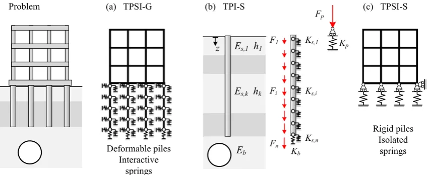
This section presents details of the TSAMs used in this paper. Two tunnel-pile-structure interaction (TPSI) approaches were adopted: a general method (Method G, referred to as TPSI-G) pro-posed byKitiyodom et al. (2005), based on deformable interacting piles, and a simplified version (Method S, referred to as TPSI-S), based on the assumption of rigid isolated piles. The simplified Method S, described inFranza et al. (2016), provides a relatively easy way to calculate tunnelling-induced settlements of piled buildings which may be useful when conducting preliminary risk assessments. A schematic representation of the two methods is shown inFig. 4.
proposed analysis method, the displacements induced by tun-nelling and building self-weight would not affect each other.
3.1. Greenfield displacement input
The prediction of tunnelling-induced soil movements may be performed with empirical, finite element, or analytical methods. Empirical methods have been used extensively in practice for the estimation of settlement trough shape because of their inherent simplicity. Empirical methods, however, do not provide reliable predictions of horizontal movements throughout the soil depth. On the other hand, finite element analyses generally require signif-icant computational effort and detailed soil constitutive model input data that may not be available. Closed-form analytical and semi-analytical solutions have been successfully adopted in tunnel-soil-structure interaction analyses, especially when hori-zontal ground displacements are important (e.g. tunnel-pile inter-action analyses), because they provide a consistent deformation pattern with depth. The closed-form expressions proposed by Loganathan and Poulos (1998)for the prediction of vertical and horizontal greenfield tunnelling-induced displacements in clays were adopted for the analyses presented in this paper. However, any greenfield displacement input could be used within the pro-posed method, thereby enhancing the versatility of the approach.
3.2. Soil springs
In this paper, the soil-pile interaction problem is modelled through vertical and horizontal linear springs distributed along the pile shaft, and by means of a vertical spring placed at the pile base; slippage and gap formation are not allowed. Several methods are available in the literature for evaluating spring stiffness. For piles subjected to passive loads due to ground movements, Kitiyodom et al. (2005)demonstrated that the integral method is most suitable when the estimation of pile internal forces, in partic-ular axial forces, is important. However, in this study, for the sake of simplicity, the horizontal and vertical soil spring stiffness were correlated to the elastic parameters of the soil with the expressions suggested by Vesic (1961) and Randolph and Wroth (1978). As shown byMylonakis and Gazetas (1998) and Huang et al. (2009), these expressions allow for a good estimation of the displacements of floating piles induced by tunnelling and external loadings at the pile heads, which are of great importance for correctly describing tunnel-piled building interaction.
The assumed values of stiffness for vertical (kz) and horizontal (kx) shaft springs (per unit-length of pile) are given in Eq.(8).
kz¼
2
p
Gsln 2rm dp
kx¼
0:65Es
dp 1
m
2s
ffiffiffiffiffiffiffiffiffi
d4pEs
EpIp 12
s
ð8Þ
whereGsis the shear modulus of soil,Esand
m
sare the Young’s mod-ulus and Poisson’s ratio, respectively, of the soil at the pile shaft,rm is an empirically determined distance beyond which the soil settle-ments become negligible, dp is the pile diameter, Lp is the pile length, and EpIp is the flexural pile stiffness. In general,rm¼
v
1v
2Lpð1m
sÞwherev
1andv
2are empirical terms depending on soil inhomogeneity (v
1v
2¼2:5 in the case of a homogeneous half-space) (Randolph and Wroth, 1978; Mylonakis and Gazetas, 1998). The stiffness of the vertical springKpbat the pile base is eval-uated with Eq.(9)(Randolph and Wroth, 1979),
Kpb¼
dpEb
1
m
2 bð9Þ
where Eb and
m
b are the Young’s modulus and Poisson’s ratio, respectively, of the soil below the pile base.3.3. General analysis method for tunnel-pile-structure interaction
The ‘General Method’ of tunnel-pile-structure interaction (TPSI) analysis (referred to as TPSI-G, refer toFig. 4) used in this paper was achieved numerically by means of the finite element method (FEM) using a displacement-based approach. Using this method, when matrix condensation is conducted for the structure with respect to the pile head nodes, the remaining degrees of freedom (dofs) of the system are the generalised displacements of the pile element nodes (i.e. vertical and horizontal displacements, and rotations). Condensation of the problem allows reduction of the dofs (i.e. the computational effort of the analysis) while preserving the rigour of the approach. The equilibrium condition of the soil-pile-structure system is expressed by the following system of lin-ear equations:
CþKsþKp
up¼fp ð10Þ
where CþKsþKp
is the global stiffness of the piled structure sys-tem,C is the soil stiffness matrix, Ks is the condensed stiffness matrix of the structure,Kpis the stiffness matrix of the pile group, andupis the displacement vector of the piled foundation. Note that
[image:5.595.80.504.65.239.2]to vertical and lateral tunnelling-induced greenfield ground move-ments, wheresis the vector of the tunnelling-induced greenfield movements. Eq.(10)may be partitioned to highlight the dofs of the pile heads connected to the superstructure (subscriptF) and of the embedded pile nodes (subscriptE):
CFF CFE CEF CEE
þ KFF 0
0 0
s
þ KFF KFE KEF KEE
p uF uE p
¼ CFF CFE CEF CEE
sF sE
ð11Þ
Piles and superstructure elements are modelled as Euler-Bernoulli elastic beams. The soil stiffness matrix is defined as
C¼A1, whereAis the soil flexibility matrix whose generic com-ponentsAijdescribe soil displacement at nodeiof the pile induced by a unit force applied at nodej. In this analysis, the interaction between nodes belonging to the same pile was neglected as well as the interaction between shaft and base nodes (i.e. pile base nodes only interact with each other). The diagonal terms of the flexibility matrix were determined starting from the stiffness val-ues obtained by Eqs.(8) and (9). In this paper, the analyses were limited to the case of a homogeneous half-space, thus the off-diagonal non-zero terms, which represent pile-soil-pile interaction contributions, were obtained on the basis of Mindlin (1936) solutions for vertical and lateral forces at the pile shaft. Concerning displacements induced at a radial distancerby vertical forces at the pile base, the off-diagonal terms were obtained from the approximate attenuation function of soil settlements, dp=ð Þ
p
r, suggested byRandolph and Wroth (1979), which was derived from the solution of a punch on the surface of a half-space.Once the equilibrium equation is solved with the inverse matrix method, the solution displacement vector,up, is obtained. Then, the displacements and deformations of the entire superstructure can be computed by displacing the dofs of the pile heads connected to the superstructure by the sub-vectoruF. Subsequently, super-structure internal forces and bending moments may be computed.
3.4. Simplified analysis method for tunnel-pile-structure interaction
The ‘Simplified Method’ for tunnel-pile-structure interaction analysis (referred to as TPSI-S) used in this paper (1) assumes the piles to be rigid, (2) neglects the pile-soil-pile interaction, and (3) disregards the horizontal soil springs. Subsequently, this procedure only requires consideration of the vertical dofs of the piles. These simplifying assumptions reduce the global tunnel-pile-structure interaction analysis to that of a building on vertical springs which account for the soil deformability, subjected to a vertical system of forces induced by tunnelling (Fig. 4(c)).
The schematic representation of the problem for a single pile case is shown in Fig. 4(b). If each pile is discretised into nþ1 nodes, it is possible to provide the following simple closed-form expressions for the stiffness of the equivalent pile-soil spring,Kp, and the resultant tunnelling-induced vertical force,Fp, at thepth pile head.
Kp¼ Xn
i¼1
kzðziÞ
D
ziþKpbFp¼ Xn
i¼1
szðziÞkzðziÞ
D
ziþszðLpÞKpbð12Þ
whereDziis the effective pile length corresponding to theith node, andszis the greenfield vertical soil movement induced by tunnel excavation at thepth pile axis line.
If a piled structure is considered, the tunnel excavation induces a system of vertical forces at the pile head level. The equilibrium equation of the system is formulated by adding the contribution
of soil stiffness to the condensed stiffness matrix of the structure. The equilibrium equation is
KsþKg
up¼fp ð13Þ
whereKsis the condensed stiffness matrix of the structure,Kgis the stiffness matrix of the soil-pile group system,upis the displacement vector of the piled foundation, andfpis the vector of the tunnelling-induced forces. The condensed stiffness matrix of the structure is a full matrix, whereas the stiffness matrix of the pile-soil system is a diagonal matrix because the pile-soil-pile interaction is neglected. The non-zero diagonal terms of Kg;ii and the terms of vector fp;i are obtained from Eq.(12). Note that, because the problem is ide-alised as an elastic structure on independent vertical elastic springs, the superstructure should be restrained in the horizontal direction by an additional external constraint (seeFig. 4(c)). Neglecting hor-izontal ground movements at the pile foundation is acceptable con-sidering that tunnel construction generally induces negligible horizontal strains in structures with continuous foundation systems at the ground level (due to the relatively high axial stiffness of the building/foundation system) (Burland et al., 2004; Dimmock and Mair, 2008). However, this may not be the case for isolated piles or a foundation with a particularly low axial stiffness at the ground level (e.g. single columns supported by a single pile not connected at the ground floor level) (Goh and Mair, 2014). In these cases, par-ticular attention should be paid in using the outcomes of the simpli-fied Method S. In the analysis presented here, solution to Eq.(13) was obtained with the inverse matrix method. Alternatively, a 3D numerical modelling software could be used. Although results pre-sented here are limited to a simple pile row foundation, this analy-sis method can account for layered soil deposits and a generic structure with a variety of pile foundation configurations.
4. Model validation
This section demonstrates that the Winkler-based methods allow for a reliable assessment of piled building displacements due to tunnel construction. The efficacy of Methods G and S was investigated by comparing results against more rigorous 3D elastic FEM analyses performed using ABAQUS (Simulia, 2010). The influ-ence of tunnel location, building configuration, as well as soil and structure stiffness were investigated. Although the analytical models allow implementation of multi-layered soil, all considered configurations correspond to vertical piles embedded in a homoge-neous half-space. Results focus on the tunnelling-induced struc-tural distortions at the foundation level (i.e. pile head movements). Pile head vertical and horizontal displacements are indicated asup
z andupx, respectively, whereas rotations are given by
u
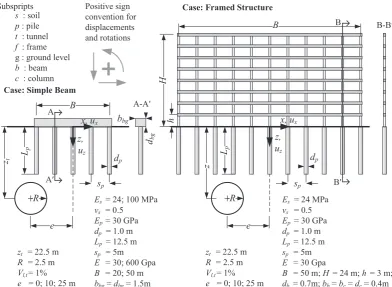
p. Tunnel-pile group interaction performed with free-pile head conditions (i.e. piles are not affected by a structure) are indicated with TPI; tunnel-pile-structure interaction analyses are denoted with TPSI.Fig. 5summarises the considered tunnel-pile-structure configurations and illustrates the adopted sign convention for dis-placements and rotations.4.1. Definition of analysis cases
Validation analyses were performed with for two structural/-foundation models: (1) simple beams with a structural/-foundation compris-ing a row of either 5 or 11 piles, and (2) a framed structure with an 11 pile foundation, each of which was supported by a pile, and with no ground-level beam connecting the columns. The sim-ple beam was given a stiffness that is representative of an equiva-lent foundation and superstructure system. Several relative soil-structure stiffness ratios, given byEs=E, where Es and Eare the Young’s modulus of the soil and superstructure, respectively, were investigated. The framed structure elements were given a Young’s modulus of 30 GPa and realistic beam and columns cross-sections (as detailed inFig. 5). The pile spacing was fixed at 5 m, hence the 5-pile building model had a widthB¼20 m, whereas the 11-pile foundation had a widthB¼50 m. The structures were located with their centre at a horizontal distanceefrom the tunnel centreline. Three different tunnel locations,e¼0;15, or 25 m, were consid-ered. The tunnel volume loss,Vl;t, was assumed equal to 1% for all the performed analyses in this paper. In this section, piles were assumed to be constrained through fixed connections to the super-structure. Both horizontal and vertical greenfield movements were considered except for the simple beam case, where only tunnelling-induced forces due to vertical greenfield movements were applied.
4.2. ABAQUS finite element models
The validation results were obtained with rigorous 3D elastic FEM analyses performed using ABAQUS. The model was composed of 3D structural bodies (beams and piles) as well as by a 3D soil mesh. Therefore, it correctly models the global interaction under the assumption of linear isotropic materials. The ABAQUS simula-tions modelled the soil and piles using 3D 8-node linear brick, reduced integration solid elements (C3D8R). The mixed
analytical-numerical approach for soil-structure interaction analy-sis used byKlar and Marshall (2008)was adopted. This ensured that the input soil displacements due to tunnelling in the numeri-cal model were consistent with those used in the Winkler-based model.
The mixed analytical-numerical analysis consists of two stages. In the first stage, all nodes of the soil model are forced to displace according to a chosen input for greenfield settlements and the reaction forces of the nodes (nodal forces required to produce the applied displacements) are recorded. In the second stage, the model is returned to its original condition (before deformation) and the selected structure is added to the model. The nodal reac-tion forces recorded in the previous stage are then applied to the model which includes the added structure. Any difference in soil displacements between the two stages of the model is due to the existence of the added structure (piles and superstructure). All other aspects of the ABAQUS model were consistent with the assumptions adopted in the Winkler-based model; tie connections at soil-pile interfaces, linear elastic isotropic materials, no contact between the soil and superstructure, and weightless materials. Furthermore, the model dimensions were set to ensure that boundary conditions did not affect results.
4.3. Validation test results
4.3.1. Simple beam model
A comparison of the ABAQUS and Winkler-based model results for the simple beam analyses are presented inFig. 6for different values of soil and equivalent structure stiffness, as well as building location. For comparison, greenfield ground movements (at the surface) are also plotted (see black dashed lines).
[image:7.595.98.491.65.352.2]predictions was assessed usingDi(Eq.(14)), which is the absolute value of the ratio between the difference in pile settlement estima-tion with the ABAQUS and the Winkler models and the maximum surface greenfield settlement of the pile group.Fig. 7shows that the accuracy is good for method G and acceptable for the simplified method S.
D
i¼uWinkler
p;z¼0 u
Abaqus p;z¼0
smax z;z¼0
ð14Þ
Particularly interesting is the settlement profile for the more flexible beam inFig. 6(a) and (d) (E¼30 GPa and 11 pile founda-tion). The data show that piles with their tips above the tunnel (i.e. within a horizontal offset less than a tunnel radius,R, from the tunnel centreline) settle more than the greenfield ground sur-face, whereas piles with their tips outside this area settle by approximately the same amount as the greenfield surface, despite the presence of the superstructure. These results fit well with the defined influence zones relating pile response to surface greenfield displacements around a tunnel (seeFig. 1).
The data illustrate that the superstructure stiffness tends to reduce the maximum relative deflection of the piled structure, where the relative deflection is the distance between the settle-ment curve and a segsettle-ment connecting two points of the curve.
For instance, in Fig. 6(b), the settlement of the 5-pile building varies almost linearly with transverse distance, giving near-zero values of relative deflection. Moreover, as expected, the super-structure shows more flexible behaviour when the ratio between soil and structure Young’s modulus and/or the ratio between struc-ture width and tunnel depth is high.
4.3.2. Framed structure model
A framed structure with isolated ground level columns was cho-sen for the validation analysis in order to emphasise effects induced by horizontal translations and rotations of the pile heads. This provides further information on the effect of structural config-uration to the overall response.
Fig. 8compares displacements and rotations of the frame struc-ture model foundation from the Winkler-based and ABAQUS mod-els; surface greenfield data are also included for comparison, when possible. Method S only accounts for the vertical dofs of piles; thus its use is only appropriate for the assessment of induced settle-ments. Displacements and rotations obtained from the tunnel-pile group interaction (TPI) analysis with a free-tunnel-pile head condition are also provided inFig. 8to highlight the effect of the frame. The data show good agreement between the ABAQUS results and both method Gðupz;upx;
u
pÞand method Sð Þupz predictions. The tunnel-pile interaction analysis again highlights that the tunnel-piles with their tips directly above the tunnel settle more than the greenfield sur-face settlements, whereas piles outside this area settle slightly less than the greenfield surface displacements. The reduction of vertical settlements due to the frame stiffness, in this case, is marginal. Fur-thermore, the shape of the structural settlement trough (i.e. curva-ture profile) is not altered by the framed building. Horizontal pile head displacements due to tunnel-pile interaction agree in magni-tude and distribution with the greenfield values. Horizontal ground movements are transferred to the buildings by the piled founda-tion and, in the TPSI analysis, frame stiffness is able to reduce the magnitude compared to the TPI displacement curve. Further-more, rotation distributions estimated in the case of TPI and TPSI differ. Interestingly, despite the connection condition of fixed pile heads, the TPSI pile head rotation distribution is qualitatively opposite to the first derivative of the frame settlement curve for [image:8.595.103.497.66.289.2]e¼0. This aspect and additional influences of the structural con-figuration are investigated further in the following section; the Fig. 7.Difference in pile settlement prediction,Di, for simple beams.
[image:8.595.91.245.598.739.2]focus of this section was to illustrate how the results Winkler-based models compare against the more rigorous ABAQUS model results.
5. Structural configuration and pile-structure connection
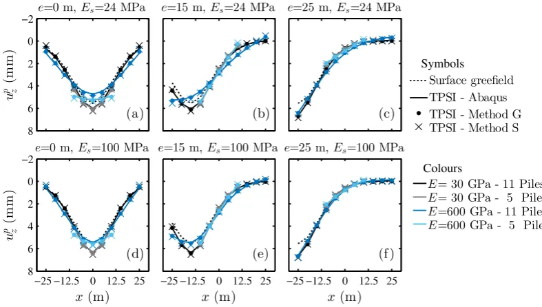
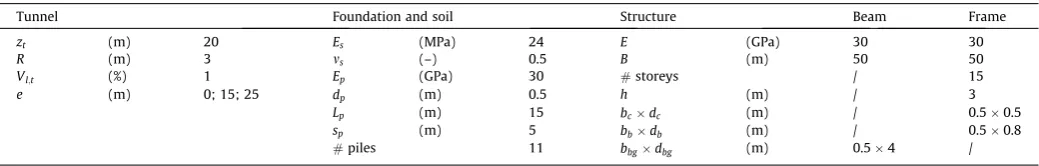
In this section, results from the ‘General Method’ of tunnel-pile-structure interaction analysis (TPSI-G) are used to evaluate the influence that structural configuration and pile-structure connec-tion detail have on building displacements. Two building models were analysed: (1) a simple beam and (2) a frame. The parameters adopted for the analyses are summarised inTable 1and results are presented inFig. 9. For comparison, greenfield displacements are also plotted. To allow for comparison of results, a unique geotech-nical domain (i.e. tunnel, soil, and foundation properties) was assumed. In addition, the two building models were given proper-ties such that maximum settlements obtained in the tunnel-pile-structure interaction analyses were equivalent (i.e. the two build-ings models had a similar stiffness). Both fixed-head (FH) and hinged-head (HH) pile-structure connections were implemented.
Note that pile head rotations have no effect on building deforma-tions and internal forces for hinged pile-structure connecdeforma-tions.
An important distinction between simple beams and framed buildings of similar stiffness is that, for the simple beams, the structural bending stiffness is concentrated at the ground level, whereas for frames, it is distributed over several storeys through the action of the columns. This significantly affects pile head move-ments and rotations resulting from tunnel-pile-structure interaction.
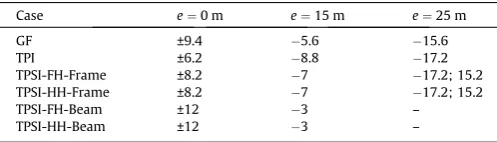
[image:9.595.107.478.65.385.2]As illustrated inFig. 9(a)–(c), the shape of the framed building settlement curves is similar to that of the TPI curves (i.e. tunnel-pile interaction with no structure included). On the contrary, the stiffness of simple beams tends to have a more significant effect on the settlement curve shape and the resulting width of the build-ing in the saggbuild-ing and hoggbuild-ing zones,BsagandBhog, respectively. To illustrate the modification ofBsagandBhog, the position of the inflec-tion point of the settlement curves inFig. 9are shown inTable 2. For the casee¼0, the inflection point offset (and therefore magni-tude ofBsag) is increased, compared to the settlement curve result-ing from TPI, more for the beam models than for the frame models. Fig. 8.Validation analysis outcomes: framed structure case.
Table 1
Model parameters - effect of structural configuration and pile-structure connection.
Tunnel Foundation and soil Structure Beam Frame
zt (m) 20 Es (MPa) 24 E (GPa) 30 30
R (m) 3 ms (–) 0.5 B (m) 50 50
Vl;t (%) 1 Ep (GPa) 30 #storeys / 15
e (m) 0; 15; 25 dp (m) 0.5 h (m) / 3
Lp (m) 15 bcdc (m) / 0.50.5
sp (m) 5 bbdb (m) / 0.50.8
[image:9.595.33.553.669.752.2]For the case ofe¼25 m, the settlement curve of the simple beam does not have an inflection point at all, indicating that the entire building is in hogging (i.e.Bhog¼B).
The structural configuration also affects horizontal foundation movements at the surface. As shown byFig. 9(d)–(f), the axial stiff-ness of the simple beam results in negligible horizontal pile head translations, whereas the framed structure is not able to prevent these movements. The horizontal movements obtained with the TPSI analysis is a reduced version of the displacements resulting from the TPI analysis. The frame resists differential pile head hor-izontal displacements through the bending stiffness of the base columns, which is less effective than the axial stiffness of horizon-tal structural elements connecting the pile heads in the beam anal-ysis. Interestingly, the moderating effect of the structure on pile head horizontal translations induces an overall building shift towards the tunnel centreline.
Finally, the understanding of pile head rotations,
u
p, requires consideration of two aspects: (1) the degree of fixity of the pile heads, provided by the overall superstructure bending stiffness at the ground level and the pile-structure connections (FH or HH);and (2) the ability of the superstructure to resist any differential horizontal movements of the foundation at the ground surface. When the frame is centred above the tunnel, TPSI analysis pile head rotation distributions are qualitatively opposite to the first derivative of the frame settlement curve (see Fig. 9(a) and (g) and note that a positive pile head rotation is anticlockwise). Pile-structure connection type (hinged or fixed) has only a marginal influence on results for this case. This happens because ground level columns, which have relatively low bending stiffness, resist differential horizontal movements between piles (i.e. drag pile heads horizontally) resulting in pile head rotations. On the other hand, for a simple beam, there is a remarkable difference in the rotations induced by hinged and fixed pile-structure connections. When the pile heads are fixed to the beam, the rotation distribu-tion has to follow the first derivative of the settlement curve in Fig. 9(a) because of the high degree of fixity at the pile heads pro-vided by the beam bending stiffness. For hinged pile heads, relative pile-beam rotations are allowed and the rotation curve shape is similar to that induced by a frame but with higher maximum val-ues because the simple beam is more efficient at reducing horizon-tal differential movements. Similar interaction mechanisms for pile head rotation are observed when the tunnel is not centred below the building (Fig. 9(h) and (i)).
Overall, the results shown inFig. 9illustrate that the choice of the structural model can have an important effect on results in a tunnel-pile-building interaction analysis.
6. Deflection ratio and horizontal strain modification factors
[image:10.595.113.495.67.385.2] [image:10.595.43.292.449.520.2]To put results in the context of the limiting tensile strain framework, this section presents a study of the effects of relative Fig. 9.Effect of structural configuration on tunnelling-induced distortions.
Table 2
Horizontal offset to inflection point,xi, of the settlement curves inFig. 9(a)–(c).
Case e¼0 m e¼15 m e¼25 m
GF ±9.4 5.6 15.6
TPI ±6.2 8.8 17.2
TPSI-FH-Frame ±8.2 7 17.2; 15.2
TPSI-HH-Frame ±8.2 7 17.2; 15.2
TPSI-FH-Beam ±12 3 –
Loganathan and Poulos (1998). This criterion was added to the analyses performed to assess the greenfield and building distortions as well as the modification factors. The results for the framed structures are compared with simple beams using a newly proposed method for determination of relative bending and axial stiffness that accounts for the structural configuration and pile geometrical distribution beneath the building (detailed in the following section). Tables 3–5 indicate the range of parameters and structural configurations assumed for the parametric analyses. The previous section (seeFig. 9), illustrated the importance of pile-structure connections on the global tunnel-pile-structure interaction for simple beams. Therefore, the analyses of the simple beams were performed for two cases: hinged (HH) and fixed (FH) pile head. Frames were only analysed for fixed pile-structure connections because of the secondary role that the rotational restraint has on the global interaction (seeFig. 9).
6.1. Deflection ratio and relative bending stiffness
6.1.1. New relative bending stiffness parameters for piled structures
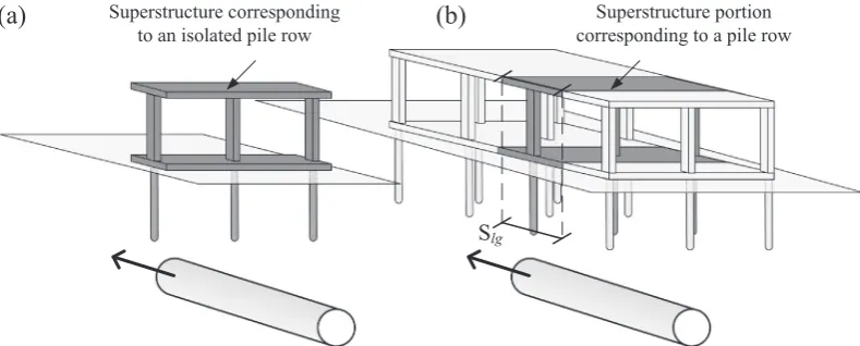
For piled foundations, it is not possible to simplify the problem to a plain strain condition. In order to define a suitable relative bending stiffness factor, the problem of a structure on a single pile row foundation is first considered (see Fig. 10(a)). For a single transverse pile row the entire superstructure contributes to the stiffening of the soil-foundation system, leading to the necessity to considerEIrather thanEI (per m run) as defined byFranzius et al. (2006) and Farrell (2010). Therefore, in these cases, the use of the following relative bending stiffness parameters are more appropriate:
(i.e. when the tunnel has passed the location of the building). By multiplying the expressions shown in Eq.(4)by the ratio between longitudinal spacing of transverse pile rows,Slg, and building lon-gitudinal length,L, the following definitions of relative bending stiffness of buildings with multiple pile rows are obtained
q
psag¼
EI EsB3sag
Slg
L
q
phog¼EI EsB3hog
Slg
L ½ m ð16Þ
whereEIðSlg=LÞis the bending stiffness of the superstructure portion corresponding to the considered transverse pile row (in kN m2). This approach permits a direct comparison of
q
for shallow founda-tions toq
pfor pile foundations. By definition, the relative stiffnesses may be evaluated fromqsag
¼q
p;r sagSlg
qhog
¼q
p;r hog
Slg
ð17Þ
This definition will be used in a subsequent section to relate design charts proposed for buildings on shallow foundations to the out-comes of the tunnel-pile-structure interaction analyses presented here. Moreover, to facilitate the description of the results, the terms primary and secondary deformation modes are used as follows: for low eccentricity cases, primary = sagging and secondary = hogging; for high eccentricity cases, primary = hogging and secondary = sagging.
6.1.2. Deflection ratio of simple beam and frame models
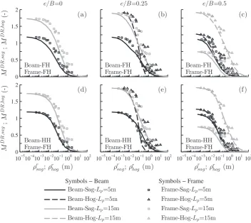
[image:11.595.93.488.579.738.2]The deflection ratio modification factors calculated from the parametric study results,MDR(Eq.(1)), are plotted against the rel-ative bending stiffness inFigs. 11 and 12. Because the analyses are performed for a single pile row, relative bending stiffness is
Fig. 11.Effects of building stiffness onMDR
forEs¼24 MPa andB= 20 m.
Fig. 12.Effects of building stiffness onMDR
[image:12.595.124.483.418.736.2]whereas the lower charts refer to fixed pile-simple beam connec-tions (FH). Frames are only analysed for fixed pile-structure con-nections (FH) because, as shown in the validation section, pile-structure connections have secondary effects on the response of framed buildings.
Figs. 11 and 12 illustrate that reduction factors are highly dependent on building eccentricity,e=B. Another important param-eter is the relative pile length,Lp=zt; data show a marked rise of
MDR for a given case with an increase of Lp=zt in both primary and secondary deformation modes (e.g. Figs. 11 and 12(a) and (d)), except for the secondary sagging deformations at high nor-malised eccentricity e=B¼0:5 (see Figs. 11 and 12(c) and (f)). Therefore, relatively long piles represent a greater potential for building damage in this context.
Furthermore, in bothFigs. 11 and 12, the modification factor trends reveal qualitative differences between the case of simple beams and framed buildings. Framed buildings undergo a gradual reduction ofMDR with relative bending stiffness in both hogging and sagging zones; on the contrary, in the case of simple beams with both fixed and hinged pile connections, the charts show that the structural deformation follows a more complex pattern, which is due to the structural continuity of the building, preventing it from responding independently in the hogging and sagging zones. For instance, in the case of a central tunnel (e=B¼0) and building widthB¼50 m (seeFig. 12(a) and (d)) hogging and sagging curves show complex and interrelated trends. After an initial decrease of both reduction factors, at approximately
q
r¼101m, there is a sharp drop of the hogging curve whereas the sagging one remains steady up to
q
r¼100m. When the hogging reduction factor reaches a value close to zero, which means that the structure is undergoing a fully sagging deformation mode, any increase in structural bending stiffness contributes to further reduce the sag-ging reduction factor.Fig. 12demonstrates that, for simple beams in both sagging and hogging greenfield zones, the structural stiff-ness is more efficient in the reduction of the secondary deforma-tion mode (the hoggingDRfor low eccentricity buildings and the saggingDRfor high eccentricity buildings). This outcome agrees with the results of centrifuge and numerical modelling analyses performed byFranzius et al. (2006) and Farrell et al. (2014), who studied the deformation induced by tunnelling on simple shells and plates, respectively. On the other hand, this may not be true for framed structures that, in this study, show a gradual reduction ofDRin both deformation zones with the increase of relative stiff-ness. In general, although the relative stiffness
q
r accounts indi-rectly for the tunnel location through Bsag and Bhog, detailed design charts should be a function of e=B and structural configuration.Additionally, comparison of results for frames and simple beams illustrates the importance of the pile-structure connection
effect of the superstructure; this is because the bending stiffness of the piles contributes to the resistance against building deforma-tion, whereas for hinged connections there would not be this stiff-ening contribution of the pile foundation.
6.2. Horizontal strains and relative axial stiffness
[image:13.595.313.542.606.729.2]Because of the capability of piles to mobilise horizontal move-ments, simple beams and framed buildings with piled foundations may undergo significant horizontal strains. This section investi-gates the effects of structural configuration and pile-structure con-nections on horizontal strain modification factors,Me, defined by Eq. (2), and introduces a unique dimensionless axial stiffness parameter for both simple beams and frame buildings. As for the analysis of relative bending stiffness, the case of a structure on a single pile row is considered. When the building has multiple transverse pile rows, it is necessary to distribute the building stiff-ness between the pile rows, as shown inFig. 10(b), in order to con-sider the appropriate portion of the building. To account for the axial stiffness of either a simple beam or a horizontal structural element connecting pile heads in framed buildings, the structural scheme shown inFig. 13was considered. This consists of a portal with a beam at the ground level connecting two pin-supports. The axial stiffness of this beam is referred to asEAbg. As shown in the validation section, for piled foundations, the pile-structure con-nection has a negligible effect on horizontal movements and there-fore strains. As a result, the conservative structural scheme based on pin-supports may be considered to be representative. Similar toGoh and Mair (2014), the frame stiffness factor,
a
f, is defined by imposing a unit differential horizontal displacement, D, between the pin-supports and calculating the external horizontal reaction force,H0, resulting ina
f ¼H0
D
¼3KbKc
h2ð2Kbþ3KcÞ þEAbg
l ½kN=m ð18Þ
The first term of
a
f represents the contribution of the portal to the overall axial stiffness of the building at the ground level whereas the latter relates to the contribution of a simple beam. To account for the soil stiffness, it would be appropriate to define the relative axial stiffness asa
f ¼
1
Es
3KbKc
h2ð2Kbþ3KcÞ þEAbg
l
" #
m
½ ð19Þ
Interestingly, the second term of this expression is similar to
a
mod¼EA=ðEsBLÞ(Eq.(3)), with the bay lengthlinstead of the build-ing widthBand the longitudinal building lengthLomitted (which is sensible considering that the soil interacts with the piles and not directly with the entire superstructure).
The cases presented inTables 3–5were also used for this anal-ysis.Fig. 14plots, for both beams and frames, the calculated values ofMehagainst
a
f, defined using Eq.(19). Results illustrate that hor-izontal strain reduction factors are not affected by the pile length,
Lp, but are influenced by building transverse width,B, and building normalised eccentricity, e=B. Moreover, Fig. 14 indicates three notable points. Firstly, the distribution of the results demonstrates the efficiency of horizontal ground level structural elements to reduce horizontal strains (for the given soil-pile foundation sys-tem, a wide range of simple beams are able to achieve a value of
[image:14.595.42.294.88.126.2]Meh¼0, whereas the stiffest frames are only able to reduceMeh to 0.4). Secondly, despite the similar trend of results for simple beams and frames, most results from the frames are below those of the simple beams; this may be due to the assumed simplified Table 3
Investigation of modification factors: combination of stiffness for simple beams.
Simple beam (15 cases) Min Max
Bending stiffness EI (kN m2
) 104 1011
[image:14.595.42.293.177.258.2]Axial stiffness EA (kN) 104 1011
Table 5
Investigation of modification factors: framed structure configurations.
Structure A B C D
E (GPa) 30 30 30 30
#storeys 2; 4; 10; 15; 30
h (m) 3 3 3 3
l (m) 5 5 5 5
[image:14.595.42.292.301.381.2]bcdc (m) 0.20.2 0.30.3 0.50.5 0.70.7 bbdb (m) 0.20.2 0.30.5 0.50.8 0.71.0 bbgdbg (m) Absent
Table 4
Investigation of modification factors: soil, tunnel and foundation parameters and configurations.
Tunnel Foundation and soil
zt (m) 20 Es (MPa) 24
R (m) 3 ms (–) 0.5
Vl;t (%) 1 Ep (GPa) 30
e=B 0; 0.25; 0.5 dp (m) 0.5
Lp (m) 5; 15
sp (m) 5
#piles 5; 11
Fig. 14.Effects of building stiffness onMeh
[image:14.595.121.485.413.739.2]head connection (hinged or fixed) to the superstructure, discussed in the previous section, is once again confirmed (by comparing results inFig. 14(a)–(c) with results in Fig. 14(d)–(f)). However, in general, for simple beam structures, at a given relative axial stiffness, the reduction factorsMehare slightly higher for the fixed pile-structure condition than for the hinged connection.
6.3. Proposed envelopes for modification factors
An additional extensive parametric analysis was conducted to provide design charts for estimation of the modification factors due to tunnelling beneath piles. Attention was focused on the geotechnical domain by considering a wide range of parameters for the piled foundations and the soil;Table 6summarises the con-sidered soil-pile foundation configurations. The superstructure properties, both simple beams and frames, were defined as in the previous section (see Tables 3 and 5). Only fixed pile-structure connections were implemented. The relative bending stiffness
q
r and the relative axial stiffnessa
findicated in Eqs. (15) and (19) were adopted. Because the tunnel-building eccentricity influences the modification factors, results for different values of e=B are
stiffness of the building, the outcomes suggest that for piled struc-tures, a fully flexible response is expected up to about
q
r¼103102m, depending on relative pile length (Fig. 15). Note that the values of the upper and lower envelopes begin to decrease for
q
r>102m. This indicates that performing a tunnel-pile interaction analysis, which neglects the contribution of the structure, may be overly conservative when
q
r>102m. Buildings start to experience negligible deformations (i.e. a fully rigid response) within the range of about
q
r¼100102m. At a given relative building stiffness, buildings on relatively long piles are more likely to undergo higher deflection ratios than buildings on short piles. Generally, the increase ofMDR withL
p=ztis due to subsurface movements having a greater effect. However, this does not apply to the estimation ofMDR;sagin the case of relatively long piles wheree=B¼0:5 (see Fig. 15(a) where values ofMDR;sag fall below the lower envelope). The presence of these outliers is prob-ably due to the efficiency of simple beams to reduce deformations due to the secondary deformation mode.
To highlight the effect of piles, the envelopes suggested byMair (2013)for shallow foundations are also plotted inFig. 15 consider-ing
q
r¼S [image:15.595.33.285.86.167.2]lg
q
and assuming a longitudinal spacing between pileFig. 15.Proposed envelopes for the estimation ofMDR
[image:15.595.121.461.490.741.2]rows ofSlg¼5 and 20 m to cover a realistic range of pile spacing. In the chart, the magnitude of the envelope translation due toSlg is minor because of the logarithmic scale of thex-axis. The proposed lower envelope is comparable to that obtained byMair (2013)for shallow foundations; this is probably due to the fact that relatively short piles are mostly affected by the distributions of surface greenfield movements, similar to the case of buildings on rafts and footings. In contrast, the upper envelopes for shallow and deep foundations illustrate the considerable detrimental role played by piled foundations in tunnel-building interaction, especially for flexible structures.
6.3.2. Horizontal strain modification factors
Upper and lower envelopes of the horizontal strain modification factor,Meh, are plotted inFig. 16together with results of the full parametric investigation. Results are distinguished between rela-tively short and long piles and for simple beam and frame models. Results inFig. 16illustrate the secondary effect ofLp=ztonMeh. On the contrary, there is a marked difference in the reduction trends of piled beam and frame models: Meh for beam models may be higher than for frames at a given relative axial stiffness. Despite this,Fig. 16indicates the suitability of the dimensionless modification factor
a
f in describing the building contribution to the reduction of differential horizontal displacements between pile heads for several soil and foundation configurations. To account for the structural scheme, two distinct upper envelopes are proposed for beams and frames, as shown inFig. 16. In general, neglecting the effects of piles for fully flexible structures may be adequate because the maximum recorded value of Meh was only slightly higher than unity. On the other hand, for partially flexible beams with
a
f >10
1m and partially flexible frames with
a
f >103m,
reduction factors decline steadily; assuming greenfield horizontal strains would be overly conservative in these cases. A rigid build-ing response should be expected for
a
f >10
3m.
Based on the envelopes for simple beams shown inFig. 16, it is interesting to notice that a rigid response is observed in most prac-tical cases of piled structures with horizontal structural elements at the ground level. For instance, a simple beam with a 0:250:25 m2cross-section andE¼30 GPa has an axial stiffness of 1:9106kN. If the building model consists only of these beams
andEs andlare assumed to be 25 MPa and 5 m, respectively, the relative axial stiffness of the system is
a
f ¼1:510
1m, which is
associated with very low value ofMehinFig. 16. Therefore, horizon-tal ground strains transferred into a piled superstructure with con-tinuous horizontal structural elements at the ground level would be negligible unless an unrealistically small axial stiffness is con-sidered. On the contrary, as indicated byGoh and Mair (2014)for frames on single footings, in the case of piled frame structures without ground level strips or rafts, differential horizontal move-ments between pile heads are expected, which may induce damage in non-structural elements, such as infill walls, or to the ground floor columns. However, horizontal strains should be negligible at the first floor level (i.e. at the top of the ground level columns) because of the constraint provided by the axial stiffness of the first-floor beam/slab.
7. Conclusions
A study of the tunnel-piled building interaction has been pre-sented in this paper based on elastic Winkler-based Two-Stage Analysis Methods (TSAMs). Analyses were limited to the case of tunnelling beneath piled elastic frame structures or simple equiv-alent beams. Results for varying levels of soil and structural stiff-ness, structural configuration, and relative foundation-tunnel location compared well with results from 3D FEM numerical mod-els. The Winkler-based TSAMs allow for a remarkable reduction of the computational cost compared to 3D FEM analyses and repre-sent a reliable and versatile tool for parametric studies. The pro-posed analysis approach allows for a detailed structural analysis that can evaluate the deformations of each member of the super-structure (i.e. beams and columns). This results in a more detailed damage assessment compared to a preliminary analysis based on the limiting tensile strain method, which only evaluates the overall degree of damage within the building.
[image:16.595.127.479.66.286.2]the displacements resulting from the tunnel-pile interaction. The structural configuration is very important; a different
response for a piled simple beam and a piled frame is expected. In particular, the structural stiffness of simple beams was found to be more efficient in reducing deformations associated with the secondary inflection mode (i.e. hogging for low eccentricity cases and sagging for high eccentricity cases). Framed struc-tures exhibited a gradual reduction of deformations in hogging and sagging but preserved the shape of the settlement curve even for relatively stiff structures. Neither the response nor the damage of framed buildings can be fully described using a simple beam model.
The pile-structure connection (hinged or fixed pile heads) plays an important role in tunnel-pile-structure interaction for simple beams and structures whose stiffness is concentrated at the ground level (i.e. frame structure with piled raft foundation). The pile-to-structure connection effect is secondary for framed buildings when pile heads are isolated or connected by slender elements, which is probably due to the relatively low bending stiffness of columns. Furthermore, the results of tunnel-structure interaction analyses suggest that hinged pile-structure connections should be adopted in equivalent simple beam analyses of framed building with relatively low bending stiffness at the ground level.
The results provided in this paper are based on the simplifying assumptions of soil linearity and perfect bonding between the pile and soil. Therefore, this work represents a first step towards the understanding of the global tunnel-pile-structure interaction. Fur-ther investigations should be carried out to clarify the influence of ground conditions, tunnel volume loss level, superstructure weight, and tunnel head excavation advancement on the global tunnel-pile-structure interaction. However, the paper provides important insight into the problem of tunnelling beneath piled structures and contributes to the definition of the key interaction phenomena and parameters involved in the tunnel-piled building response.
Acknowledgements
This work was supported by the Engineering and Physical Sciences Research Council (EPSRC) [grant number EP/K023020/1, EPSRC Doctoral Training Award].
References
Basile, F., 2014. Effects of tunnelling on pile foundations. Soils Found. 54 (3), 280– 295.
Burland, J.B., Mair, R.J., Standing, J.R., 2004. Ground performance and building response due to tunnelling. In: Jardine, R.J., Potts, D.M., Higgins, K.G. (Eds.),
China, pp. 259–266.
Franza, A., Marshall, A.M., 2015. Semi-analytical prediction of ground movements due to shallow tunnels in sand. Proceedings of the XVI ECSMGE Geotechnical Engineering for Infrastructure and Development, vol. 2. Edinburgh, United Kingdom, pp. 461–466.
Franzius, J.N., Potts, D.M., Burland, J.B., 2006. The response of surface structures to tunnel construction. Proc. ICE – Geotech. Eng. 159 (1), 3–17.
Giardina, G., DeJong, M.J., Mair, R.J., 2015. Interaction between surface structures and tunnelling in sand: centrifuge and computational modelling. Tunn. Undergr. Space Technol. 50, 465–478.
Goh, K.H., Mair, R.J., 2011. Building damage assessment for deep excavations in Singapore and the influence of building stiffness. Geotech. Eng. J. SEAGS AGSSEA 42 (3), 1–12.
Goh, K.H., Mair, R.J., 2014. Response of framed buildings to excavation-induced movements. Soils Found. 54 (3), 250–268.
González, C., Sagaseta, C., 2001. Patterns of soil deformations around tunnels. Application to the extension of Madrid Metro. Comput. Geotech. 28 (67), 445– 468.
Huang, M., Zhang, C., Li, Z., 2009. A simplified analysis method for the influence of tunneling on grouped piles. Tunn. Undergr. Space Technol. 24 (4), 410–422. Jacobsz, S.W., Standing, J.R., Mair, R.J., Hagiwara, T., Sugiyama, T., 2004. Centrifuge
modelling of tunnelling near driven piles. Soils Found. 44 (1), 49–56. Kaalberg, F.J., Teunissen, E.A.H., van Tol, A.F., Bosch, J.W., 2005. Dutch research on
the impact of shield tunnelling on pile foundations. In: Bakker, K.J., Bezuijen, A., Broere, W., Kwast, E.A. (Eds.), Proceedings of the 5th International Symposium on Geotechnical Aspects of Underground Construction in Soft Ground. Taylor & Francis - Balkema, Amsterdam, the Netherlands, pp. 123–131.
Kitiyodom, P., Matsumoto, T., Kawaguchi, K., 2005. A simplified analysis method for piled raft foundations subjected to ground movements induced by tunnelling. Int. J. Numer. Anal. Meth. Geomech. 29 (15), 1485–1507.
Klar, A., Marshall, A.M., 2008. Shell versus beam representation of pipes in the evaluation of tunneling effects on pipelines. Tunn. Undergr. Space Technol. 23 (4), 431–437.
Loganathan, N., Poulos, H.G., 1998. Analytical prediction for tunneling-induced ground movements in clays. J. Geotech. Geoenviron. Eng. 124 (9), 846–856. Loganathan, N., Poulos, H.G., Xu, K.J., 2001. Ground and pile-group responses due to
tunnelling. Soils Found. 41 (1), 57–67.
Losacco, N., Burghignoli, A., Callisto, L., 2014. Uncoupled evaluation of the structural damage induced by tunnelling. Géotechnique 64 (8), 646–656.
Mair, R., 2013. Tunnelling and deep excavations: ground movements and their effects. In: Anagnostopoulos, A., Pachakis, M., Tsatsanifos, C. (Eds.), Proceedings of the 15th European Conference on Soil Mechanics and Geotechnical Engineering – Geotechnics of Hard Soils – Weak Rocks (Part 4). IOS Press, Amsterdam, the Netherlands, pp. 39–70.
Mair, R., Williamson, M., 2014. The influence of tunnelling and deep excavation on piled foundations. In: Yoo, C., Park, S.-W., Kim, B., Ban, H. (Eds.), Proceedings of the 8th International Symposium on Geotechnical Aspects of Underground Construction in Soft Ground. Taylor and Francis - Balkema, Seoul, South Korea, pp. 21–30.
Mair, R.J., Taylor, R.N., 2001. Elizabeth House: settlement predictions. Building Response to Tunnelling: Case Studies from Construction of the Jubilee Line Extension, vol. 1. Thomas Telford, London, United Kingdom, pp. 195–215. Mair, R.J., Taylor, R.N., Burland, J.B., Taylort, R.N., 1996. Prediction of ground
movements and assessment of risk of building damage due to bored tunnelling. In: Mair, R.J., Taylort, R.N. (Eds.), Proceedings of the International Symposium on Geotechnical Aspects of Underground Construction in Soft Ground. Balkema, Rotterdam, London, United Kingdom, pp. 713–718.
Maleki, M., Sereshteh, H., Mousivand, M., Bayat, M., 2011. An equivalent beam model for the analysis of tunnel-building interaction. Tunn. Undergr. Space Technol. 26 (4), 524–533.
Marshall, A., Mair, R., 2011. Tunneling beneath driven or jacked end-bearing piles in sand. Can. Geotech. J. 48 (12), 1757–1771.