sophisticated devices, whose performance is very sensitive to the quality of power supply. Power quality problem is an occurrence manifested as a nonstandard voltage, current or frequency that results in a failure of end use equipment. Dynamic Voltage Restorer (DVR) is a solution to improve voltage quality, which is the most efficient and effective modern custom power device used in power distribution networks. Its appeal includes lower cost, smaller size, and its fast dynamic response to the disturbance. This paper presents modeling, analysis, and simulation of DVR in MATLAB/SIMULINK, which includes PI controller and Fuzzy Controller. The results exhibit clearly the performance of the DVR using Fuzzy Logic Controller mitigates the power quality issues.
Keywords: DVR, Power Quality, Voltage Sag, Voltage swell, PI Controller, Fuzzy logic Controller.
I. INTRODUCTION
Nowadays, modern industrial devices are mostly based on electronic devices such as programmable logic controllers and electronic drives. The electronic devices are very sensitive to disturbances and become less tolerant to power quality problems such as voltage sags, swells and harmonics. Voltage dips are considered to be one of the most severe disturbances to the industrial equipment. Voltage support at a load can be achieved by reactive power injection at the load point of common coupling. The common method for this is to install mechanically switched shunt capacitors in the primary terminal of the distribution transformer. The mechanical switching may be on a schedule, via signals from a supervisory control and data acquisition (SCADA) system, with some timing schedule, or with no switching at all. The disadvantage is that, high speed transients cannot be compensated. Some sag is not corrected within the limited time frame of mechanical switching devices. Transformer taps may be used, but tap changing under load is costly. The family of custom power controllers originally included three basic devices: the Solid-state Breaker (SSB), the Static Compensator (DSTATCOM) and the Dynamic Voltage Restorer (DVR). DVRs are a class of custom power devices for providing reliable distribution power quality. They employ a series of voltage boost technology using solid state switches for compensating voltage sags/swells. The DVR applications are mainly for sensitive loads that may be drastically affected by fluctuations in system voltage. Reliability is expanded to include power quality goals: no power interruptions, tight voltage regulation, low harmonic distortion, and low phase unbalance. But the DVR has plenty of applications in distribution systems aimed to improve the quality and reliability of the power supplied to the end-user. It can be used to prevent non-linear loads from polluting the rest of the distribution system. The rapid response of the DVR makes it possible to provide continuous and dynamic control of the power supply including voltage and reactive power compensation, harmonic mitigation and elimination of voltage sags and swells.
II. DYNAMIC VOLTAGE RESTORER
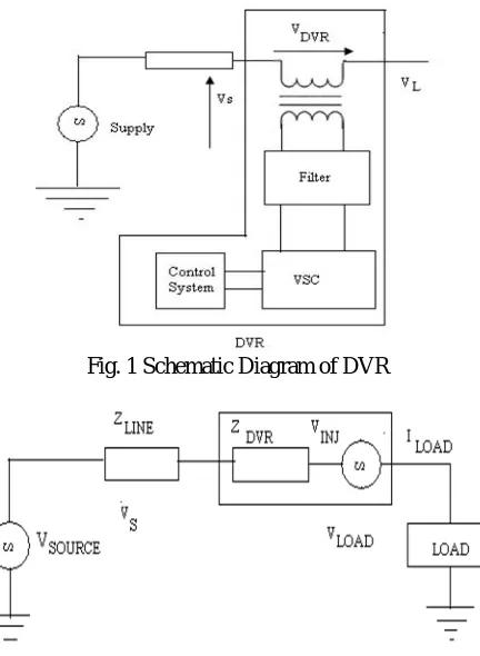
Fig. 1 Schematic Diagram of DVR
Fig. 2 Equivalent Diagram of DVR
A. The components of DVR
1) Injection Transformer: The Injection/Booster transformer is a specially designed transformer that attempts to limit the coupling of noise and transient energy from the primary side to the secondary side. Its main tasks are: connects the DVR to the distribution network via the HV-windings and transforms and couples the injected compensating voltages generated by the voltage source converters to the incoming supply voltage. In addition, the Injection/ Booster transformer serves the purpose of isolating the load from the system. It is one unit three phase construction.
2) Harmonic Filter: The main task of harmonic filter is to keep the harmonic voltage content generated by the voltage source converters to the permissible level. It has a small rating approximately 2% of the load MVA connected to delta-connected tertiary winding of the injection transformer.
3) Voltage Source Converter: A VSC is a power electronic system consists of a storage device and switching devices, which can generate a sinusoidal voltage at any required frequency, magnitude, and phase angle. In the DVR application, the VSC is used to temporarily replace the supply voltage or to generate the part of the supply voltage which is missing.
4) Storage Devices: The purpose is to supply the necessary energy to the VSC via a dc link for the generation of injected voltages. The different kinds of energy storage devices are superconductive magnetic energy storage (SMES), batteries, and capacitance.
5) Capacitor: DVR consists of a capacitor having large rating. In addition, it is used for stiff DC voltage for the input of an inverter.
B. DVR Working
1) Protection Mode: If the over current on the load side exceeds a permissible limit due to short circuit on the load or large inrush current, the DVR will be isolated from the systems by using the bypass switches and supplying another path for current.
2) Standby Mode (Voltage Injected by DVR is Zero): In the standby mode the booster transformer’s low voltage winding is shorted through the converter. No switching of semiconductors occurs in this mode of operation and the full load current will pass through the primary.
Fuzzy logic (FL) controller is the heart of fuzzy set theory. The major features are the use of linguistic variables rather than numerical variables. This control technique relies on human capability to understand the systems behavior and is based on quality control rules. Fuzzy Logic provides a easy way in providing definite conclusion based upon vague, noisy, imprecise, ambiguous or missing given information.
1) The Fuzzyfication interfaceconverts the given input to linguistic definitions.
2) The Knowledge Base consisting of a data base and a rule base.
3) A Decision Making unit, simulating a human decision process, and interface the fuzzy control action from the knowledge of the control rules and the linguistic variable definitions.
4) Defuzzification interface yields a non-fuzzy control action from an inferred fuzzy control action.
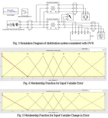
Fig. 3 Simulation Diagram of distribution system considered with DVR
[image:3.595.114.488.343.749.2]Fig. 4 Membership Function for Input Variable Error
Fig. 6 Membership Function for output Variable
Fig. 7 The set of fuzzy control rules
IV. RESULTS AND DISCUSSIONS
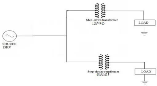
[image:4.595.162.417.471.611.2]Single line diagram of the system considered without and with DVR is shown respectively comprised by a 13KV, 50HZ source supplies to bus where a load is connected.
Fig. 8 Basic configuration of system without DVR
A. Parameters for System Considered Without DVR
Source Voltage 13KV
Line resistance and inductance of feeder 1 0.0002 Ω, 0.001 H
Line resistance and inductance of feeder 2 0.0002 Ω, 0.001 H
Step-down transformer on feeder 1 13KV/415V
Step-down transformer on feeder 2 13KV/415V
Load R=0.1 Ω and L=0.1926H
ER / E LP MP SP S SN MN LN
LP PB PB PB PM PM PS Z
MP PB PB PM PM PS Z NS
SP PB PM PM PS Z NS NM
S PM PM PS Z NS NM NM
SN PM PS Z NS NM NM NB
MN PS Z NS NM NM NB NB
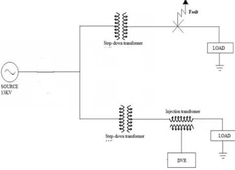
Fig. 9 Basic system configuration with DVR
B. Parameters for System Considered With DVR
DC voltage 200V
Capacitance 750μs
Inverter Specifications IGBT based 3 Arms, 6 pulse,
Carrier frequency=10kHz, Sample time = 5μs
Injection transformer 100/1000V
1) Case 1: Voltage sag
[image:5.595.178.419.445.583.2]To analyze the working of DVR for voltage sag compensation a fault is applied to the system for time duration of 200ms.The DVR is simulated to be in operation only for the duration of fault.
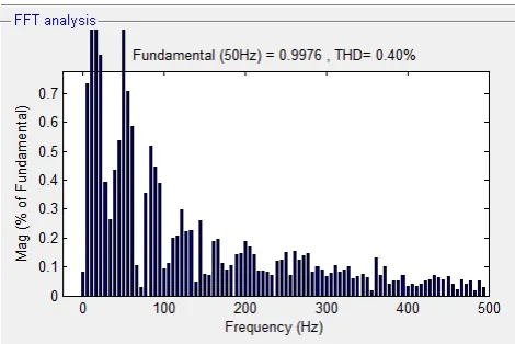
[image:5.595.179.413.607.737.2]Fig. 10 FFT analysis for Source Voltage without DVR
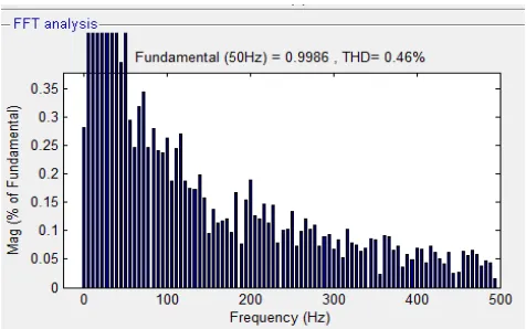
Fig. 12 FFT analysis for Load Voltage with DVR using Fuzzy Logic Controller
So, from the above comparison it is clear that by using Fuzzy Logic Controllers we can achieve the more efficient Total Harmonic distortion (THD).
2) Case 2: Voltage swell
[image:6.595.188.409.375.550.2]To analyze the working of DVR for voltage swell compensation a fault is applied to the system for time duration of 200ms.The DVR is simulated to be in operation only for the duration of fault.
[image:6.595.187.405.575.733.2]Fig. 13 FFT analysis for Source voltage without DVR
Fig. 15 FFT analysis for Load voltage with DVR using Fuzzy Logic Controller
So, from this case we conclude that the Total harmonic distortion using the Fuzzy Logic controller is more efficient than the PI Controller.
V. CONCLUSIONS
The most effective custom power device for mitigating the power quality problems in the electrical distribution system is DVR. The above results show that dvr mitigates the sag very fast and provide the excellent regulation of voltage. The balanced and unbalanced faults are handled by the dvr without any difficulties and inject the voltage to correct the fault situation. The dvr keeps the load voltage balanced and maintains the constant nominal value. The above simulation based FFT results clearly shows that fuzzy logic controller exhibited a better performance in improving the load voltage to the normal condition.
REFERENCES
[1] S. H. Hingorani “Introducing custom power” IEEE spectrum, vol.32 no.6 June 1995 p 41- 48 [2] Benachaiba Chellali, FERDI Brahim, “Voltage Quality Improvement
[3] Using DVR,” Electrical Power Quality and Utilizations, Journal Vol. XIV, No. 1, 2008
[4] M. Bollen. “Understanding Power Quality Problems, voltage sags and Interruptions.” IEEE press, 1999
[5] Ming Fang, Mister I. Gardiner, Andrew MacDougall, Granta A. Matheson, A novel series dynamic voltage restorer for distribution system, IEEE 1998 [6] C. Fitzer, M. Barnes and P. Green, “Voltage Sag Detection Technique for a Dynamic Voltage Restorer”, IEEE Trans. Industry Applications, Vol. 40(1),
Jan.2004, pp. 203 – 212
[7] Power Quality Enhancement Using Custom Power Devices by A. Ghosh and G. Ledwich. 2002. Kluwer Academic Publishers
S. Choi, J. Li and M. Vilathgamuwa, “A Generalized Voltage Compensation Strategy for Mitigating the Impacts of Voltage Sags/Swells”, IEEE Trans. Power Delivery, Vol. 20(3)