A Thermodynamic Modeling of the Fe
Nd
Sb System
Wei Wang
+, Tingan Liu, Huilei Song, Songyi Xue, Wanyou Zhang, Haifeng Zhang,
Lanhe Zhang, Yanping Jia, Nan Wang, Xin Cheng and Chunhui Zeng
Department of Chemical Engineering, Northeast Dianli University, Jilin city, 132012, China
The FeNdSb system was assessed by means of the CALculation of PHAse Diagram (CALPHAD) technique. The solution phase, liquid, bcc, fcc, dhcp, and rhom, were described by the substitutional solution model. The compounds Fe17Nd2, Fe17Nd5, Nd2Sb, Nd5Sb3, Nd4Sb3,
NdSb, NdSb2, Nd6Fe13Sb (¸1), Nd3Fe3Sb7(¸3), NdFeSb3(¸4), and NdFe4Sb12 (¸6) were treated as stoichiometric compounds. The ternary
compounds Nd2Fe5¹xSb10¹y(¸2,x=1.48,y=5.12) and NdFe1¹xSb2(¸5) were modeled as (Fe,Va)0.4667(Nd)0.1333(Sb,Va)0.4 and (Fe,Va)0.25
-(Nd)0.25(Sb)0.5, respectively. A set of self-consistent thermodynamic parameters of the FeNdSb system was obtained in this study. [doi:10.2320/matertrans.M2015333]
(Received August 17, 2015; Accepted November 25, 2015; Published January 25, 2016)
Keywords: ironneodymiumantimony system, calculation of phase diagram (CALPHAD) technique, phase diagram, thermodynamic description
1. Introduction
Binary skutterudite structured compounds, MX3 (where
M=Co, Rh, Ir or other metal atom; X=P, As, Sb or other pnictogen), are usually observed to have a high Seeback coefficient and high electrical conductivity, however, its merit value remains low due to its high thermal conductivity. An effective method to lower its thermal conductivity is to obtain filled skutterudite, which has much lower thermal conduc-tivity in comparison to the corresponding binary skutterudite compounds with metal elements, especially rare earth elements.1)
The addition of rare earth elements can change the stability and crystal structure of the corresponding binary skutterudite compounds. Therefore, filled skutterudite compounds, such as RT4X12 (where R=rare earth or alkaline earth metal,
T=transition metal (Fe, Ru, Os), X=pnictogen), were considered as a promising thermoelectric material due to the enhanced Seeback coefficient.25) Developing a reliable
thermodynamic description and related theoretical analysis of these systems is believed to be useful for the design of future materials.
The thermodynamic description of the FeSb system, which was adopted in this study, was assessed by Zhang.6)
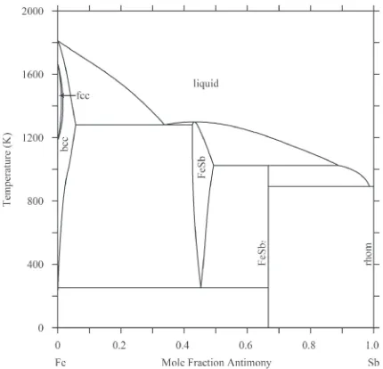
Figure 1 represents the calculated FeSb phase diagram from Zhang’s study.6)The FeNd, the NdSb and the FeNdSb
systems were assessed by means of the CALPHAD technique on the basis of the experimental data found in literature. A set of self-consistent parameters for the calculation of the phase equilibria and the thermochemical properties of the system are provided.
2. Literature Information
2.1 The binary system
Phase relations in the FeNd binary system were experimentally determined by Terekhova et al.,7) Schneider et al.,8) Landgraf et al.,9) and Hennemann et al.10)
Kubaschewski,11) Zhang et al.,12) Okamoto,13) and Marazza
et al.14)also reviewed this system. Various other experimen-tal research of this system can be found in different studies (e.g. Refs. 1519)). Two binary intermetallic compounds Fe17Nd2and Fe17Nd5were confirmed at present. Table 1 lists
the experimental results for this system.
The FeSb system has been optimized by various studies,6,2022) with the main differences being the model of
the intermetallic compound FeSb used in each study. In the studies of Peiet al.20)and Boaet al.,21)FeSb was described
by a two-sublattice model Fe(Fe,Sb). In the studies of Zhang6) and Li et al.,22) FeSb was treated by a three-sublattice model (Fe,Va)1/3(Fe,Va)1/3(Sb)1/3 (the symbol
“Va” represents a vacancy in this work). It is reasonable to adopt the three-sublattice model in this study because FeSb has a hexagonal structure of the NiAs prototype,2325)and this kind of three-sublattice model is used to describe the CoSb compound in the thermodynamic assessment of the CoSb binary system.26,27)The thermodynamic parameters obtained
by Zhang6) were adopted in the present work, as the
calculated results were in good agreement with the
Fig. 1 FeSb phase diagram, plotted using data from Zhang.6)
[image:1.595.320.535.299.506.2]experimental data when the thermodynamic description by Zhang6)was used.
The Gibbs energy per mole of formula unit FeSb is expressed by Zhang6)as follows:
GFeSbm ¼yIFeyIIFeGFeSbFe:Fe:SbþyFeI yIIVaGFeSbFe:Va:SbþyIVayIIFeGFeSbVa:Fe:Sb
þyIVayIIVaGFeSbVa:Va:Sbþ1=3RTðyIFelnyIFeþyIValnyIVa
þyIIFelnyIIFeþyIIValnyIIVaÞ þEGFeSbm ð1Þ
EGFeSb
m ¼yIFeyIVaðyIIVa0LFeSbFe,Va:Va:SbþyIIFe0LFeSbFe,Va:Fe:SbÞ
þyIIVayIIFeðyIFe0LFeSbFe:Va,Fe:SbþyIVa0LFeSbVa:Va,Fe:SbÞ ð2Þ whereyI andyII are the site fractions of Fe or Va in thefirst and the second sublattices. The parameterGFeSb::Sb represents the Gibbs energies of the compound FeSb when thefirst and the second sublattices are completely occupied by Fe or Va.
0LFeSb
Fe,Va::Sb and 0LFeSb:Fe,Va:Sb are the interaction parameters
between Fe and Va in the first and the second sublattices when the third sublattice is occupied by Sb, and the other sublattice is occupied by Fe or Va. It is assumed that
0LFeSb
Fe,Va:Va:Sb ¼0LFeSbFe,Va:Fe:Sb and 0LFeSbFe:Va,Fe:Sb¼0LFeSbVa:Va,Fe:Sb
in order to decrease the number of thermodynamic parame-ters on the basis of the general rule of simplification during the assessment procedure.
Kobzenkoet al.,28)Samsonovet al.,29)and Koberet al.30)
determined the phase equilibria of the NdSb system. Massalski,31)Okamoto32)and Predel33)reviewed this system, and Cacciamani et al.34) assessed this system. Five binary intermetallic compounds Nd2Sb, Nd5Sb3, Nd4Sb3, NdSb and
NdSb2 were confirmed, and Table 2 lists the experimental
results for this system.
2.2 The FeNdSb ternary system
In the FeNdSb ternary system, six ternary compounds
are known: Nd6Fe13Sb (Nd6Fe13Si-type tetragonal structure,
denoted as¸1here),35,36)Nd2Fe5¹xSb10¹y(x=1.48,y=5.12, a high-temperature phase above 1273 K, La2Fe5¹xSb10¹y-type tetragonal structure, denoted as ¸2(t) here),35)Nd2Fe7¹xSb6¹y (x=3.04,y=1.03, a low-temperature phase below 1273 K, Nd2Fe7¹xSb6¹y-type orthorhombic symmetry structure, de-noted as¸2(o) here),35)Nd3Fe3Sb7 (Nd3Fe3Sb7-type
hexago-nal structure, denoted as ¸3 here),35,37) NdFeSb3 (LaPdSb3
-type orthorhombic structure, denoted as ¸4 here),35,37)
NdFe1¹xSb2 (ZrCuSi2-type tetragonal structure, denoted as
¸5 here),35,38)and NdFe4Sb12 (LaFe4P12-type cubic structure,
denoted as ¸6here).3)
The 773 K isothermal section in the whole composition range was determined by Zeng et al.39) Five ternary compounds (e.g. ¸1, ³NdFe2.5Sb2 (i.e. ¸2), ¸4, ¸5, ¸6), 20
three-phase regions, and 36 two-phase regions were con-firmed in this isothermal section in the study of Zenget al.39)
The 870 K isothermal section in the composition range of ³33100 at% Sb was determined by Solugub and Salamakha.40)Two ternary compounds (e.g. ¸
5and ¸6), and
6 three-phase regions were definitely confirmed in the composition range of ³50100 at% Sb in the study of Solugub and Salamakha.40)
The 1073 K isothermal section in the composition range of ³40100 at% Sb was determined by Nasir et al.37) Five ternary compounds¸1,¸2,¸3,¸4and¸5were confirmed in this
section.
3. Thermodynamic Models
3.1 Unary phases
[image:2.595.49.550.84.188.2]The Gibbs energy function for the element i (i=Fe, Nd, Sb) in the phase ¤(¤=liquid, bcc (¡Fe or¤Fe), fcc (£Fe),
Table 1 Invariant reactions of the FeNd system.
Reaction Type Calculated results Experimental data
14)
T(K) x(Nd) T(K) x(Nd)
liq.+bcc¼fcc Peritectic 1667 9.87©10¹2 2.10©10¹5 3.10©10¹5 1667 1.07©10¹1 ® ®
liq.+fcc¼Fe17Nd2 Peritectic 1481 2.99©10¹1 2.19©10¹5 ® 1481 3.04©10¹1 ® ®
fcc¼Fe17Nd2+bcc Eutectic 1185 4.95©10¹7 ® 2.19©10¹7 1185 ® ® ®
liq.+bcc¼dhcp Peritectic 1141 9.17©10¹1 9.99©10¹1 9.97©10¹1 1136 9.04©10¹1 ® 9.99©10¹1
liq.+Fe17Nd2¼Fe17Nd5 Peritectic 1025 7.14©10¹1 ® ® 1025 7.09©10¹1 ® ®
liq.¼Fe17Nd5+dhcp Eutectic 959 7.65©10¹1 ® 9.93©10¹1 958 7.81©10¹1 ® 9.99©10¹1
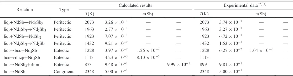
Table 2 Invariant reactions of the NdSb system.
Reaction Type Calculated results Experimental data
32,33)
T(K) x(Sb) T(K) x(Sb)
liq.+NdSb¼Nd4Sb3 Peritectic 2073 3.26©10¹1 ® ® 2073 3.74©10¹1 ® ®
liq.+Nd4Sb3¼Nd5Sb3 Peritectic 1963 2.77©10¹1 ® ® 1963 3.27©10¹1 ® ®
liq.+NdSb¼NdSb2 Peritectic 1923 7.07©10¹1 ® ® 1923 6.72©10¹1 ® ®
liq.+Nd5Sb3¼Nd2Sb Peritectic 1432 9.21©10¹2 ® ® 1432 1.53©10¹1 ® ®
liq.¼bcc+Nd2Sb Eutectic 1228 3.97©10¹2 1.26©10¹2 ® 1228 6.27©10¹2 1.04©10¹2 ®
bcc¼dhcp+Nd2Sb Eutectic 1113 4.23©10¹3 8.10©10¹5 ® 1113 ® ® ®
liq.¼NdSb2+rhom Eutectic 873 9.48©10¹1 ® 9.99©10¹1 899 9.81©10¹1 ® ®
[image:2.595.47.545.232.361.2]bcc(¢Nd), dhcp(¡Nd) or rhombohedral (Sb)) is described as follows,
G¤iðTÞ ¼0G¤iðTÞ HiSERð298:15 KÞ
¼aþbTþcTlnT þdT2þeT3
þfT1þgT7þhT9 ð3Þ whereHiSER(298.15 K) is the molar enthalpy of the element i at 298.15 K in its Standard Element Reference (SER) state, i.e. bcc for Fe, dhcp for Nd, and rhombohedral for Sb. The Gibbs energy of the element i, G¤iðTÞ, in its SER state is denoted by GHSERi, where GHSERiis described by,
GHSERi¼0G¤iðTÞ HiSERð298:15 KÞ ð4Þ
In the present study, the Gibbs energy functions are taken from the Scientific Group Thermodata Europe (SGTE) pure elements database compiled by Dinsdale.41)
3.2 Solution phases
In the FeNdSb system, there are five solution phases (liquid, fcc, bcc, rhom, and dhcp), which were modeled by the substitutional solution model. Their Gibbs energies are given by:
G¤m¼xFeG¤FeðTÞ þxNdG¤NdðTÞ þxSbG¤SbðTÞ
þRTðxFelnxFeþxNdlnxNdþxSblnxSbÞ þEG¤m ð5Þ where Ris the ideal gas constant; xi(i=Fe, Nd, Sb) is the mole fraction of the pure element i;EG¤
mis the excess Gibbs
energy expressed by the Redlich-Kister-Muggianu formal-ism,42,43)
EG¤
m¼xFexNd
X
n nL¤
Fe,NdðxFexNdÞn
þxFexSbX n
nL¤
Fe,SbðxFexSbÞn
þxNdxSb
X
n nL¤
Nd,SbðxNdxSbÞn
þxFexNdxSbL¤Fe,Nd,Sb ð6Þ
where nL¤i,j (i, j=Fe, Nd, Sb, and iºj) are thenth binary interaction parameters between elements i and j, and their general form is,
L¤¼aþbTþcTlnTþdT2þeT3þfT1 ð7Þ
In most cases, the first one or two terms on the right-hand side in eq. (7) (i.e.“a”or“a+bT”) are used according to the temperature dependence of the experimental data.L¤Fe,Nd,Sbis the ternary interaction parameter and is expressed as:
L¤Fe,Nd,Sb¼xFe0L¤Fe,Nd,SbþxNd1L¤Fe,Nd,SbþxSb2L¤Fe,Nd,Sbð8Þ
where nL¤
Fe,Nd,Sb ¼a¤nþb¤nT (n=0, 1, 2), a¤n and b¤n are the
parameters to be optimized in this work.
3.3 Stoichiometric intermetallic compounds
The compounds Fe17Nd2, Fe17Nd5, Nd2Sb, Nd5Sb3,
Nd4Sb3, NdSb and NdSb2 are treated as stoichiometric
compounds (denoted as MxNy) in the present work. The Gibbs energy per mole of formula unit MxNyis expressed as follows:
GMxNy
m ¼xGHSERMþyGHSERNþG MxNy
f þ
mgGMxNy m
ð9Þ
whereGMxNy
f is the Gibbs energy of formation per mole of
formula unit MxNy, andmgG
MxNy
m is the magnetic contribution
to the Gibbs energy, which will be discussed in Section 3.5. The Gibbs energies of the ternary compounds¸1,¸3,¸4and
¸6 per mole of formula unit are expressed with:
G¸1
m ¼0:65GHSERFeþ0:3GHSERNd
þ0:05GHSERSbþG¸f1 ð10Þ G¸3
m ¼0:2308GHSERFeþ0:2308GHSERNd
þ0:5384GHSERSbþG¸f3 ð11Þ G¸4
m ¼0:2GHSERFeþ0:2GHSERNd
þ0:6GHSERSbþG¸f4 ð12Þ G¸6
m ¼0:2353GHSERFeþ0:0588GHSERNd
þ0:7059GHSERSbþG¸f6 ð13Þ
whereG¸1 f ,G¸
3 f ,G¸
4
f , andG¸ 6
f are the Gibbs energies
of formation per mole of formula unit ¸1, ¸3, ¸4 and ¸6,
respectively.
3.4 Intermetallic compounds¸2and¸5
The phase ¸2(i.e. ¸2(o) as mentioned in Section 2.2) was
described by a three-sublattice model (Fe,Va)0.4667(Nd)0.1333
-(Sb,Va)0.4. Thefirst sublattice of the phase¸2is occupied by
Fe and Va; the second sublattice is occupied by Nd; the third sublattice is occupied by Sb and Va. The Gibbs energy per mole of formula unit (Fe,Va)0.4667(Nd)0.1333(Sb,Va)0.4 is
described as,
G¸2
m ¼yIFeyIINdyIIISbGFe:Nd:Sb¸2 þyIFeyIINdyIIIVaG¸Fe:Nd:Va2
þyIVayIINdyIIISbG¸2
Va:Nd:Sbþy I
VayIINdyIIIVaG¸Va:Nd:Va2
þ0:4667RTðyIFelnyIFeþyIValnyIVaÞ
þ0:1333RTðyIINdlnyIINdÞ
þ0:4RTðyIIISblnyIIISbþyIIIValnyIIIVaÞ
þyIFeyIVa yIINdyIIISbX n
nL¸2
Fe,Va:Nd:Sbðy I
Fey
I VaÞ
n
þII NdyIIIVa
X
n nL¸2
Fe,Va:Nd:VaðyIFeyIVaÞ n
!
þyIIISbyIIIVa yIFeyIINdX n
nL¸2
Fe:Nd:Sb,VaðyIIISbyIIIVaÞ n
þyIVayIINdX n
n L¸2
Va:Nd:Sb,Vaðy III
Sby
III VaÞ
n
!
ð14Þ
where in eq. (14),yI
i(i=Fe or Va) andyIIIj ( j=Sb or Va) are
the site fractions of components i, and j in thefirst, and third sublattices respectively. The parameter G¸2
i:Nd:j represents the
Gibbs energy of the stable or metastable compound in which the first, second and third sublattices are respectively occupied by i, Nd and j, respectively, which are relative to the enthalpies of pure Fe, Nd, and Sb in their SER states.
nL¸2
Fe,Va:Nd:jare thenth interaction parameters between Fe and
Va in thefirst sublattice while the second, and third sublattice is occupied by Nd, and j, respectively.nL¸2
i:Nd:Sb,Vaare thenth
interaction parameters between Sb and Va in the third sublattice while thefirst, and second sublattice is occupied by i, and Nd, respectively.
The phase ¸5 was described by a three-sublattice model
et al.3) and Leither-Japer and Rogl.38) The first sublattice
of the phase ¸5 is occupied by Fe and Va; the second, and
the third sublattice is occupied by Nd, and Sb, respectively. The Gibbs energy per mole of formula unit (Fe,Va)0.25
-(Nd)0.25(Sb)0.5is described as,
G¸5
m ¼yIFeyIINdyIIISbGFe:Nd:Sb¸5 þyIVayIINdyIIISbG¸Va:Nd:Sb5
þ0:25RTðyIFelnyIFeþyIValnyIVaÞ
þ0:25RTðyIINdlnyIINdÞ þ0:5RTðyIIISblnyIIISbÞ
þyIFeyIVa yIINdyIIISbX n
nL¸5
Fe,Va:Nd:SbðyIFeyIVaÞ n
!
ð15Þ
where in eq. (15), yIi (i=Fe or Va) is the site fractions of components i in the first sublattice. The parameter G¸2
i:Nd:Sb
represents the Gibbs energy of the stable or metastable compound in which the first sublattices is occupied by i, which is relative to the enthalpies of pure Fe and Va in their SER states. nL¸2
Fe,Va:Nd:Sb is the nth interaction parameters
between Fe and Va in thefirst sublattice, while the second, and the third sublattices are occupied by the compounds Nd and Sb, respectively.
3.5 The magnetic contribution to the Gibbs energy The magnetic contribution to the Gibbs energy mgGm is described by
mgG
m¼RTlnð¢þ1Þfð¸0Þ ð16Þ
where ¢ is a quantity related to the total magnetic entropy, which in most cases is set equal to the Bohr magnetic moment per mole of atoms;¸Ais defined asT/Tc, andTcis the
critical temperature for magnetic ordering (i.e. the Curie temperature (Tc) for ferromagnetic ordering and the Néel
temperature (TN) for antiferromagnetic ordering); f(¸A)
represents the polynomials obtained by Hillert and Jarl44)
based on the magnetic specific heat of iron, i.e.
for¸0<1:
fð¸0Þ ¼1 1
A
79ð¸0Þ1 140p þ
474 497
1
p1
ð¸0Þ3
6 þ
ð¸0Þ9
135 þ
ð¸0Þ15
600
ð17Þ
for¸0>1:
fð¸0Þ ¼ 1
A
ð¸0Þ5
10 þ
ð¸0Þ15
315 þ
ð¸0Þ25
1500
ð18Þ
where A¼ 518 1125þ1169215975
1
p1
and p depends on the structure, 0.4 for bcc structure and 0.28 for the others.
For the solid solution phase¤ (¤=bcc, fcc, dhcp) in the FeNd system,TC¤ and¢¤are described as:
TC¤¼xFe0TC Fe¤ þxNd0TCNd¤ þxFexNdL¤TC ð19Þ
¢¤¼x
Fe0¢¤FeþxNd0¢Nd¤ þxFexNdL¤¢ ð20Þ
where LºT
C and L
º
¢ are the magnetic interaction parameters between Fe and Nd. Due to a lack of magnetic data and the very low solubility of Nd in the solid solution phases,14)both the magnetic interaction parameters LºTC and Lº¢ are set to zero in the present work.
For the intermetallic compounds FemNdn(i.e. Fe17Nd2and
Fe17Nd5), TCFemNdn and ¢FemNdn are taken from Landgraf
et al.9)and Hallemanset al.,45)as listed in Table 1.
4. Assessment Procedure
A general rule for selection of the reasonable and self-consistent thermodynamic parameters during the assessment procedure is that only those coefficients whose values were determined by various kinds of experimental information can be adjusted.46) This procedure was carried out by the PARROT module of the Thermo-Calc software.47)
The thermodynamic parameters of the FeNd and NdSb binary systems were carefully evaluated for assessing the Fe NdSb ternary system. The thermodynamic parameters of the ternary FeNdSb system were optimized on the basis of experimental data available in the literature.37,39,40) All the
calculated phase diagram and the calculated thermochemical data, which will be presented in Section 5, were reproduced from the thermodynamic evaluated parameters.
5. Results and Discussion
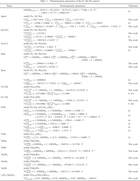
[image:4.595.312.541.541.759.2]The thermodynamic parameters of the FeNdSb system obtained in this study are listed in Table 3.
Figure 2 represents the calculated FeNd phase diagram using the experimental data obtained from the liter-ature710,1519)review. The miscibility gap in the liquid phase at high temperatures does not appear until 10,000 K in this calculated phase diagram. Table 1 lists the invariant reactions of the FeNd system. Figure 3 represents the calculated
Table 3 Thermodynamic parameters of the FeNdSb system*.
Phase Thermodynamic parameters Reference
liquid
GHSERSb_low=¹9242.9+156.1547T¹30.5131T©ln(T)+7.7488©10¹3T2
¹3.0034©10¹6T3+100625.0T¹1 6)
model (Fe, Nd, Sb)1
0Lliq:
Fe,Nd¼2831:1824;1L liq:
Fe,Nd¼6289:8072;2L liq:
Fe,Nd¼5317:4315 This work
0Lliq:
Fe,Sb¼ 16500þ9:8000T;1L liq:
Fe,Sb¼ 9000:0þ5:2000T;2L liq:
Fe,Sb¼ þ5500:0 6)
0Lliq:
Nd,Sb¼ 306284:3þ59:8857T;1L liq:
Nd,Sb¼ 1591:3þ7:1957T;2L liq:
Nd,Sb¼ þ43959:85:5472T This work
bcc(A2) model (Fe, Nd, Sb)1(Va)1
0LbccðA2Þ
Fe,Nd:Va¼ þ121536:1 This work
0LbccðA2Þ
Fe,Sb:Va¼3512:0þ21:0000T;1L bccðA2Þ
Fe,Sb:Va¼ 29000:0 6)
0LbccðA2Þ
Nd,Sb:Va¼ 196538:9þ8:2637T This work
fcc(A1) model (Fe, Nd, Sb)1(Va)1
0LfccðA1Þ
Fe,Nd:Va¼114718:62:3022T This work
0LfccðA1Þ
Fe,Sb:Va¼3950:0þ14:0000T;1L fccðA1Þ
Fe,Sb:Va¼ 15000:0 6)
dhcp model (Fe, Nd, Sb)1(Va)1
GdhcpFe ¼GHSERFeþ5000:0;GdhcpNd ¼GHSERNd;G dhcp
Sb ¼GHSERSbþ5000:0 (298 K<T<6000 K) 0Ldhcp
Fe,Nd:Va¼ þ29686:9þ4:4826T This work
0Ldhcp
Nd,Sb:Va¼ 155634:0þ4:0766T This work
rhom model (Fe, Nd, Sb)1(Va)1
Grhom
Fe ¼GHSERFeþ5000:0;GrhomNd ¼GHSERNdþ5000:0;GrhomSb ¼GHSERSb (298 K<T<2000 K) 0Lrhom
Fe,Sb:Va¼ þ100000:0 6)
0Lrhom
Nd,Sb:Va¼ 202133:7þ73:0523T;1LrhomNd,Sb:Va¼ 68658:7 This work
Fe17Nd2 model (Fe)17(Nd)2
0GFe17Nd2
Fe:Nd ¼17GHSERFeþ2GHSERNd161745:0þ83:9210T This work
0TFe17Nd2
C Fe:Nd¼ þ327:0000;0¢FeFe:Nd17Nd2ð®BÞ ¼ þ2:3000 9, 45)
Fe17Nd5 model (Fe)17(Nd)5
0GFe17Nd5
Fe:Nd ¼17GHSERFeþ5GHSERNd174481:3þ92:3811T This work
0TFe17Nd5
C Fe:Nd¼ þ503:0000;0¢ Fe17Nd5
Fe:Nd ð®BÞ ¼ þ2:3000 9, 45)
FeSb model (Fe,Va)1/3(Fe,Va)1/3(Sb)1/3 GFeSb
Fe:Fe:Sb¼2=3GHSERFeþ1=3GHSERSb6950:0þ5:3000T 6)
GFeSb
Fe:Va:Sb¼1=3GHSERFeþ1=3GHSERSb Low7100:0þ2:8000T
þ0:3373TlnT0:01014T2þ2:3027105T3þ15000:0T1 6)
GFeSb
Va:Fe:Sb¼1=3GHSERFeþ1=3GHSERSb1590:02:1000T 6)
GFeSb
Va:Va:Sb¼1=3GHSERSbþ5522:6þ1:3000T 6)
0LFeSb
Sb:Fe,Va:Va¼0LFeSbSb:Fe,Va:Fe¼ 6200:04:0000T 6)
0LFeSb
Sb:Fe:Va,Fe¼0LFeSbSb:Va:Va,Fe¼ 3196:21:5573T 6)
FeSb2 model (Fe)1/3(Sb)2/3
0GFeSb2
Fe:Sb¼ ð1=3Þ GHSERFeþ ð2=3Þ GHSERSb12195:0þ4:6000T 6)
NdSb2 model (Nd)1(Sb)2
0GNdSb2
Nd:Sb ¼GHSERNdþ2GHSERSb244516:1þ18:1768T This work
NdSb model (Nd)1(Sb)1
0GNdSb
Nd:Sb¼GHSERNdþGHSERSb243313:5þ39:6335Tþ73992:0T1 This work
Nd4Sb3 model (Nd)4(Sb)3
0GNd4Sb3
Nd:Sb ¼4GHSERNdþ3GHSERSb803501:8þ141:6638T This work
Nd5Sb3 model (Nd)5(Sb)3
0GNd5Sb3
Nd:Sb ¼5GHSERNdþ3GHSERSb879246:5þ170:2136T This work
Nd2Sb model (Nd)2(Sb)
0GNd2Sb
Nd:Sb ¼2GHSERNdþGHSERSb304113:1þ63:6888T This work
¸1(Fe13Nd6Sb1) model (Fe)0.65(Nd)0.3(Sb)0.05
0G¸1
Fe:Nd:Sb¼0:65GHSERFeþ0:30GHSERNdþ0:05GHSERSb18665:0 This work
enthalpies of formation of the compounds in the FeNd system at 973 K, compared with the experimental data from Hennemannet al.10)
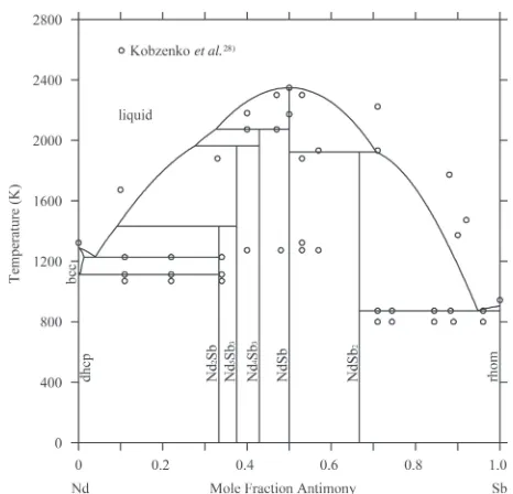
Figure 4 represents the NdSb phase diagram calculated using the experimental data from Kobzenko.28)The temper-ature of the miscibility gap for this calculated phase diagram is ³6267 K, which is an acceptable result. Table 2 lists the invariant reactions of the NdSb system. Figure 5 represents the calculated enthalpy of formation in the NdSb system at 298 K, compared with the experimental data from Borsese
et al.48)
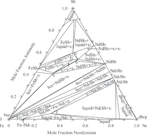
Figures 6, 7 and 8 represent the isothermal sections of the FeNdSb system, at 773 K, 870 K and 1073 K, respectively, in the entire composition range calculated using the present
thermodynamic description. In Fig. 6, all 20 three-phase regions are in good agreement with the experimental data in the entire composition range from Zenget al.39)
In Fig. 7, the calculated phase equilibria of the thermody-namic section at 870 K using the present thermodythermody-namic parameters are in good agreement with the experimental data in the composition range of ³33100 at% Sb from Sologub and Salamakha.40) Raghavan49) reviewed this isothermal section and predicted 3 three-phase regions (e.g. bcc(Fe)+ FeSb+¸5, bcc(Fe)+¸5+NdSb and bcc(Fe)+Nd4Sb3+NdSb),
which were not drawn by Sologub and Salamakha.40)As seen
in Fig. 7, the three-phase region bcc(Fe)+FeSb+¸2 in the
study of Raghavan49) was changed to ¸
2+FeSb+¸5, ¸2+
FeSb+bcc(Fe) and¸2+bcc(Fe)+¸5in this study. Continued:
Phase Thermodynamic parameters Reference
¸2(o)
(Fe7¹xNd2Sb6¹y,
x=3.04,y=1.03)
model (Fe,Va)0.4667(Nd)0.1333(Sb,Va)0.4
0G¸2
Fe:Nd:Sb¼0:4667GHSERFeþ0:1333GHSERNdþ0:4GHSERSbþ73121:9
236:4631Tþ0:1261T2 This work
0G¸2
Va:Nd:Sb¼ þ0:1333GHSERNdþ0:4GHSERSb27441:8þ5:2845Tþ9865:6T1 This work
0G¸2
Fe:Nd:Va¼0:4667GHSERFeþ0:1333GHSERNdþ227:0þ2:5249T This work
0G¸2
Va:Nd:Va¼ þ0:1333GHSERNdþ5000:0 ¸3(Fe3Nd3Sb7) model (Fe)0.2308(Nd)0.2308(Sb)0.5384
0G¸3
Fe:Nd:Sb¼0:2308GHSERFeþ0:2308GHSERNdþ0:5384GHSERSb17261:2
23:0875T1:4038107T1 This work
¸4(FeNdSb3) model (Fe)0.2(Nd)0.2(Sb)0.6
0G¸4
Fe:Nd:Sb¼0:2GHSERFeþ0:2GHSERNdþ0:6GHSERSbþ136:3868
114:6092Tþ0:06393T2 This work
¸5(Fe1¹xNdSb2, x=0.4)
model (Fe,Va)0.25(Nd)0.25(Sb)0.5
0G¸5
Fe:Nd:Sb¼0:25GHSERFeþ0:25GHSERNdþ0:5GHSERSbþ181792:9
532:8385Tþ0:2887T2 This work
0G¸5
Nd:Nd:Sb¼0:25GHSERNdþ0:5GHSERSb56129:032þ4:5112T This work
0L¸5
Fe,Va:Nd:Sb¼ 5000:0 This work
¸6(Fe4NdSb12) model (Fe)0.2353(Nd)0.0588(Sb)0.7059
0G¸6
Fe:Nd:Sb¼0:2353GHSERFeþ0:0588GHSERNdþ0:7059GHSERSb20416:7þ0:7320T This work *In J/mol of the formula unit.
Fig. 3 Enthalpy of formation at 973 K in the FeNd system calculated
using experimental data from Hennemannet al.10) Fig. 4 NdSb phase diagram calculated using experimental data from
[image:6.595.310.543.350.574.2] [image:6.595.61.283.353.571.2]Based on the experimental data from Zeng et al.39) and
Nasir,37)the calculated results in Figs. 6, 7 and 8 have similar
phase equilibria in the composition range of 033 at% Sb. Due to the phase equilibria of the FeNd binary system, the main differences were: dhcp+Nd2Sb+¸1 and dhcp+
Fe17Nd5+¸1 in Figs. 6 and 7, liquid+Nd2Sb+¸1, liquid+
Fe17Nd2+¸1and dhcp+Nd2Sb+liquid in Fig. 8.
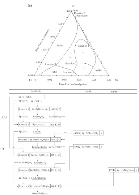
Figure 9(a) represents the predicted projection of the liquidus surfaces in the composition range 90100 at% Sb (i.e. Sb-rich corner) in the FeNdSb system, calculated using the present thermodynamic description. Figure 9(b) represents the partial predicted invariant reaction scheme which contains¸6phase. So a thermodynamic description and
the related theoretical analysis of this system in this work (e.g. the calculation in Fig. 9) is believed to be useful for the design of skutterudite-based thermoelectric materials.
6. Conclusions
A thermodynamic model of the FeNdSb system was assessed on the basis of experimental data obtained from the literature review. A set of self-consistent thermodynamic parameters for describing the Gibbs energies of individual phases as functions of composition and temperature were derived. The theoretical calculations made using the thermodynamic description from this study showed good agreement with experimental data taken from the literature presently available.
Acknowledgments
This work was supported by the Science and Technology Development Project of Jilin Provincial Science and
Fig. 5 Enthalpy of formation at 298 K in the NdSb system and comparison with measured and calculated values from Borseseet al.48)
Fig. 6 Isothermal section of the FeNdSb system at 773 K, calculated using the present thermodynamic description.
Fig. 7 Isothermal section of the FeNdSb system at 870 K, calculated using the present thermodynamic description.
[image:7.595.310.546.66.287.2] [image:7.595.61.279.68.276.2] [image:7.595.50.289.324.545.2] [image:7.595.308.546.333.551.2]Technology Department (Grant Nos. 20140520100JH and 20140204043GX), Science and Technology Development Project of Jilin Municipal Science and Technology Bureau (Grant No. 201467008), Research Fund for the Doctoral
Program of Northeast Dianli University (Grant No. BSJXM-201224). Thanks to the Royal Institute of Technology Sweden and CompuTherm LLC for supplying Thermo-Calc software.
[image:8.595.76.526.58.689.2]REFERENCES
1) G. S. Nolas, D. T. Morelli and T. M. Tritt:Annu. Rev. Mater. Sci.29
(1999) 89.
2) T. X. Liu, X. F. Tang, W. J. Xie, T. G. Yan and Q. J. Zhang:J. Rare Earths25(2007) 739.
3) C. B. H. Evers, W. Jeitschko, L. Boonk, D. J. Braun, T. Ebel and U. D. Scholz:J. Alloys Compd.224(1995) 184.
4) J. S. Zhang, H. J. Chen and J. H. Lin:J. Alloys Compd.311(2000) 109.
5) E. Bauer, St. Berger, A. Galatanu, Ch. Parl, M. Della Mea, H. Michor, G. Hilscher, A. Grytsiv, P. Rogl, D. Kaczorowski, L. Keller, T. Hermannsdörfer and P. Fischer:Physica B312313(2002) 840.
6) Y. Zhang: PhD Thesis, University of Science and Technology Beijing, (2009).
7) V. F. Terekhova, E. V. Maslava and Y. M. Savilsky: Russ. Metall.3
(1965) 128.
8) G. Schneider, E.-T. Hening, G. Petzow and H. H. Stadelmaier: Z. Metallkde.78(1987) 694.
9) F. J. G. Landgraf, G. S. Schneider, V. Villas-Boas and F. P. Missell:
J. Less-Common Met.163(1990) 209.
10) K. Hennemann, H. L. Lukas and H. J. Schaller: Z. Metallkd.84(1993) 668.
11) O. Kubaschewski: Iron-Binary Phase Diagrams, (Springer, Berlin, 1982).
12) W. Zhang, G. Liu and K. Han:J. Phase Equilib.13(1992) 645.
13) H. Okamoto:J. Phase Equilib.18(1997) 106.
14) R. Marazza, P. Riani and G. Cacciamani:Inorg. Chim. Acta361(2008) 3800.
15) G. Che, J. Liang and X. Wang: Sci. Sin. (Ser. A)29(1986) 1172. 16) F. Faudot, M. Harmelin and J. Bigot:Scr. Metall.23(1989) 795.
17) Y. Y. Wang, N. Q. Liu, Z. Z. Tian and X. R. Chang: Acta Metall. Sin.
23(1987) B149 (in Chinese).
18) Y. He, X. R. Chang, Z. Z. Tian, C. M. Hsiao, M. H. Wang, H. B. Lu, Y. Y. Wang and N. Q. Liu:Scr. Metall.19(1985) 79.
19) W. Zhang, X. Li, G. Liu and S. Pan: unpublished research, (1987), cited in 12).
20) B. Pei, B. Björkman, B. Sundman and B. Janson:Calphad19(1995) 1.
21) D. Boa, S. Hassam, G. Kra, K. P. Kotchi and J. Rogez:Calphad32
(2008) 227.
22) C. R. Li, D. M. Zhu, Y. B. Zhang, Z. M. Du, C. P. Guo, J. Q. Li and J.-C. Tedenac:Calphad47(2014) 23.
23) L. D. Dudkin and N. K. Abrikosov: Russian J. Inorg. Chem.2(1957) 212.
24) J. Naud and D. Parijs:Mater. Res. Bull.7(1972) 301.
25) L. A. Panteleimonov and I. A. Babanskaya: Moscow University Chem. Bull.28(1973) 94.
26) Y. B. Zhang, C. R. Li, Z. M. Du and T. Geng:Calphad32(2008) 56.
27) Y. B. Zhang, C. R. Li, Z. M. Du and C. P. Guo:Calphad33(2009) 405.
28) G. F. Kobzenko, V. B. Chernogorenko, E. L. Martinchuk, K. A. Lynchak and R. V. Skolozdra: Metallofizika41(1972) 87.
29) G. V. Samsonov, M. N. Abdusalyamova, Kh. Shokirov and S. A. Pryakhina: Izv. Akad. Nauk SSSR Neorg. Mater.10(1974) 1951. 30) V. I. Kober, V. A. Dubinin, S. P. Raspopin and S. R. Kanevskii: Zh. Fiz.
Khim.59(1985) 1839.
31) T. B. Massalski (ed.): Binary Alloy Phase Diagrams, 2nd ed., (Materials Information Soc., Materials Park, Ohio, ASM International, 1990) vol. 3.
32) H. Okamoto: J. Phase Equilib.15(1994) 229.
33) B. Predel: Phase equilibria, crystallographic and thermodynamic data of binary alloys, Landolt-Börnstein - Group IV Physical Chemistry, (1997) 5H: 1.
34) G. Cacciamani, R. Ferro and H. L. Lukas: Z. Metallkd.83(1992) 669. 35) A. Leithe-Jasper: PhD Thesis, University of Vienna, (1994). 36) J. M. D. Coey, Q. N. Qi, K. G. Knoch, A. Leithe-Jasper and P. Rogl:
J. Magn. Magn. Meter.129(1994) 87.
37) N. Nasir, A. Grytsiv, P. Rogl, D. Kaczorowski and H. S. Effenberger:
Intermetallics18(2010) 2361.
38) A. Leither-Jasper and P. Rogl:J. Alloys Compd.203(1994) 133.
39) L. M. Zeng, P. L. Qin, L. Q. Nong, J. L. Zhang and J. P. Liao:J. Alloys Compd.437(2007) 84.
40) O. Sologub and P. Salamakha:J. Alloys Compd.285(1999) L16.
41) Dinsdale A T. SGTE pure elements (unary) database, Version 4.5, (2006).
42) O. Redlich and A. T. Kister:Ind. Eng. Chem.40(1948) 345.
43) Y. M. Muggianu, M. Gambino and J. P. Bros: J. Chim. Phys.72(1975) 83.
44) M. Hillert and M. Jarl:Calphad2(1978) 227.
45) B. Hallemans, P. Wollants and J. R. Roos:J. Phase Equilib.16(1995) 137.
46) H. L. Lukas and S. G. Fries:J. Phase Equilib.13(1992) 532.
47) B. Sundman, B. Jansson and J. O. Andersson:Calphad9(1985) 153.
48) A. Borsese, R. Ferro, R. Capelli and S. Delfino:J. Less-Common Met.
55(1977) 77.