Modification of Primary Mg
2Si Crystals in Hypereutectic
Mg-Si Alloy by Application Alternating Current
Jun Du
1;2;*and Kazuhiko Iwai
11
Department of Materials, Physics and Energy Engineering, Graduate School of Engineering, Nagoya University, Nagoya 464-8603, Japan
2School of Materials Science and Engineering, South China University of Technology, Guangzhou 510640, P.R. China
The effect of application alternating current on the modification of primary Mg2Si crystals in the hypereutectic Mg-4.8 mass%Si alloy has been investigated in the present study. The liquidus and eutectic temperatures of the Mg-4.8 mass%Si alloy are 761C and 638C, respectively. An alternating current of 60 A with frequency of 1 kHz was applied into the hypereutectic Mg-Si melt from different starting temperatures (770, 740, 700 and 670C) till 630C. The results show that primary Mg
2Si crystals could be refined effectively by application alternating current. The average sizes of primary Mg2Si crystals were decreased to almost a half after being subjected to the alternating current. The starting temperature of the application alternating current is a very significant factor to determine the size uniformity of the primary Mg2Si crystals, while it has no obvious effect on the average size of the primary Mg2Si crystals. The refined primary Mg2Si crystals have the lowest average size and the highest uniformity in sizes when the hypereutectic Mg-Si melt was treated by application alternating current from the starting temperature of 700C. [doi:10.2320/matertrans.MRA2008235]
(Received July 25, 2008; Accepted December 24, 2008; Published February 25, 2009)
Keywords: magnesium silicon alloys, primary Mg2Si crystals, application alternating current, microstructure refinement
1. Introduction
Magnesium alloys, the lightest metal structural materials, have been extensively paid attention to being applied in the automobile industry during the past two decades, in order to reduce fuel consumption and lower waste gas emission.1–3) Among the broad range of commercial magnesium alloys, the aluminum bearing magnesium alloys, such as AZ91D (Mg-9Al-0.8Zn) and AM60B (Mg-6Al-0.4Mn), take a dominating position of consumption for automobile applications.1–5) However, this group of magnesium alloys have poor creep resistance at temperatures above 125C because the
Mg17Al12 phase existed in the Mg-Al based alloys has poor
thermal stability and its discontinuous precipitation can result in substantial grain boundary sliding at elevated temper-atures.1–5)Therefore, the Mg-Al based alloys were limited to be applied in the powertrain components, such as engine blocks up to 200C and engine pistons up to 300C. Creep
resistance is a major requirement for use of magnesium alloys in automobile powertrain components that are currently made of aluminium or cast iron.2,3)
Up to now, many investigations have been carried out to improve the creep resistance for magnesium alloys. Several kinds of magnesium alloys have been developed with higher creep resistance.3–9)Among these new alloys, the magnesium alloys containing Mg2Si having excellent creep resistance
have been paid attention extensively, since Mg2Si compound
exhibits a high melting temperature of 1085C and high
hardness of4:5109Pa.3,8,9)In particular, the hypereutectic Mg-Si alloys have high potential as structural materials for elevated temperature applications.3) However, the hyper-eutectic Mg-Si alloys prepared by ordinary ingot metallurgy process have very low ductility and strength due to the large primary Mg2Si crystal size and the brittle eutectic phase. It is
well known that the refinement of microstructures is one of
the effective routes to improve mechanical properties for metal products. The die casting, which has been widely used to produce magnesium components, is not suitable for the hypereutectic Mg-Si alloys due to their high liquidus temperatures.3)Some other advanced processing techniques such as hot extrusion,10,11) rapid solidification,12) and me-chanical alloying13)have been applied to produce alloys with fine Mg2Si crystals uniformly dispersed in Mg-matrix.
Compared with these techniques, the ingot metallurgy process is a more practical method, because it is commer-cially available at low production cost and can be accepted by the engineering community for general applications.
For the hypereutectic Mg-Si alloys prepared by ingot metallurgy process, their microstructures were traditionally refined by addition of refiners, such as rare earth element of yttrium,14)compound containing boron of KBF
4.15)However,
the material composition becomes complex upon such addition, which makes the recycling of used materials difficult. Therefore, an alternative method for the develop-ment of hypereutectic Mg-Si alloys with refining micro-structures and high strength is desired.
It has long been established that electromagnetic vibration can effectively refine the microstructures for a large range of metals prepared by the ingot metallurgy process.16–27) This route has an excellent advantage of making no change to the composition of the treated alloys. Many studies have been focused on the modification effect of electromagnetic vibration on the eutectic and primary Si crystals in the Al-Si alloys.20–23) Unfortunately, few works have been per-formed on the modification of primary and eutectic Mg2Si
phase in the Mg-Si alloys treated by electromagnetic vibration.
In the present study, the modification effect of electro-magnetic vibration induced by application alternating current on the primary Mg2Si crystals in the hypereutectic Mg-Si
alloys was investigated in order to develop an effective route to refine Mg2Si crystals in the hypereutectic Mg-Si alloys.
2. Experimental Procedure
Industrial pure Mg (99.9 mass% purity) and Si (99 mass% purity) were used as starting materials. Charges of about 3 kg with the nominal composition of Mg-5 mass%Si alloy were prepared as the experiment materials in the present study. The solidification characteristic of the prepared Mg-Si alloy was confirmed in order to designate experimental conditions. The prepared Mg-Si alloy of about 100 g was melt using MgO crucible with inner diameter of 30 mm and then was cooled in a furnace. A K-type thermocouple was inserted into the melt and the cooling curve was recorded using digital recorder (Keyence, GR-3500 type). The cooling curve is shown in Fig. 1. The primary Mg2Si crystals began to
precipitate from this Mg-Si melt from 761C and the eutectic
reaction occurred at about 638C. Judged from Mg-Si binary
alloy phase diagram,28)as shown in Fig. 2, the silicon content in the prepared Mg-Si alloy is approximately 4.8 mass% in the present study.
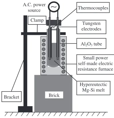
The samples treated by application alternating current were prepared as following. The hypereutectic Mg-Si alloy of about 25 g was melt at 800C in a mild steel crucible using an
electric resistance furnace under a protective flux cover (45 mass%MgCl2, 35 mass%KCl, 5 mass%CaF2, 15
mass%-NaCl). The hypereutectic Mg-Si melt was manually stirred for 1 min using a magnesia rod for homogenization, and then was held for additional 10 min. Then, the slag was cleaned and the melt was poured into an Al2O3 tube which was
preheated to 700C using a small power self-made electric
resistance furnace. This Al2O3 tube was held with clamp
fixed on a bracket in advance, as shown in Fig. 3. The size of the Al2O3tube is 21 mm in inner diameter, 25 mm in outer
diameter and 70 mm in height.
After the melt was poured into the Al2O3 tube, a couple
of tungsten electrodes (3 mm in diameter) were inserted into the melt quickly. The distance between the two tungsten electrodes was 12 mm. The tungsten electrodes were covered using Al2O3pipe with size of 3 mm in inner diameter, 5 mm
in outer diameter and 60 mm in height. The end part of the tungsten electrode with length of 5 mm was not covered to apply alternating current into the melt. The distance between
the end of tungsten electrodes and the bottom of the Al2O3
tube was 10 mm. A K-type thermocouple was fixed on one of the two tungsten electrodes and the temperature of the melt was recorded automatically using digital recorder (Keyence, GR-3500 type). The temperature was begun to record from about 770C. And then, the small power self-made electric resistance furnace was turned off and pulled off. The Al2O3
pipe filled with the hypereutectic Mg-Si melt was air-cooled. The alternating current of 60 A with frequency of 1 kHz was applied immediately when the melt was cooled to the designated temperature. The designated temperatures were 770, 740, 700 and 670C in the present study, as shown in
Fig. 2. The alternating current was turned off when the sample temperature was 630C, at which the melt was fully
solidified. For comparison, a sample without the application alternating current was prepared. Therefore, five samples were prepared in the present study.
The cylindrical ingots were cut longitudinally along the middle line parallel to the electrodes. Then, metallographic samples were cut at the position that was 20 mm from the bottom of the ingots. The samples for microstructure observation were prepared using a standard procedure with
0 5 10 15 20 25 30
500 550 600 650 700 750 800
2 4 5
748 754 760 766 772
761°C
Temperature,
T
/
°
C
Time, t / min
638 °C
Temperature,
T
/
°
C
Time, t / min
3
Fig. 1 The cooling curve of the prepared hypereutectic Mg-Si alloy cooled with furnace.
0 5 10 15 20 25 30 35 40
500 600 700 800 900 1000 1100 1200
Liquid
670 °C 700 °C 740 °C 770 °C
Mg
4.8 mass%Si
650°C
1.34
637.5°C
Mg
2
Si
Temperature,
T
/
°
C
mass% Si
Fig. 2 The phase diagram of Mg-Si binary alloy.28)
A.C. power source
Hypereutectic Mg-Si melt Brick
Small power self-made electric resistance furnace Clamp
Al2O3 tube
Tungsten electrodes Thermocouples
Bracket
∼
[image:2.595.58.283.71.242.2] [image:2.595.314.538.74.238.2] [image:2.595.325.524.284.489.2]a final polishing with 0.05mmalumina suspension. After that, the samples were etched with 3 vol%HF solution for 1 min. The etched samples were observed by a scanning electron microscope (SEM) (Keyence, VE-7800). The middle area between the two tungsten electrodes was selected as SEM observation area, as shown in Fig. 4. The size of the observed area was1515mm2.
More than five pictures were taken for every sample from the observed area. In the present study, the length of primary trunk of the dendritic Mg2Si crystal was measured as the size
of Mg2Si crystal. If the primary trunk directions were
differentiated difficultly for some Mg2Si crystals, the lengths
along several directions for one crystal were measured and the longest length as its size. All Mg2Si crystals existed in
one picture taken from the observed area were measured. After that, Mg2Si crystals in another picture were
continu-ously measured till 200 primary Mg2Si crystals for every
sample were measured, then the 200 data of sizes were analyzed by statistical method to improve the veracity of judgment of modification effect of the application alternating current. The average value and standard deviation for the 200 primary Mg2Si crystals were used to evaluate the
modification effect of the application alternating current on the primary Mg2Si crystal in the hypereutectic Mg-Si alloy.
3. Results
3.1 Cooing curves
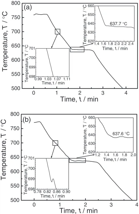
The cooling histories for all samples were recorded and analyzed. It was found that the application alternating current has no obvious effect on the cooling history and eutectic temperature based on the cooling curves for all samples. The average cooling rates from 760 till 640C and eutectic
temperature for all samples are almost identical. They are about 1.9C/s and 638C, respectively. The cooling curves
for the samples without treatment and treated by application alternating current from 700 till 630C are illustrated in
Fig. 5. In comparison with them, it was found that there was a slight rise of temperature after alternating current of 60 A was applied into the melt.
3.2 SEM observations of primary Mg2Si phase
Figure 6 shows that SEM images of microstructures for the hypereutectic Mg-Si alloy without treatment. For this sample,
its microstructure consists mainly of three constituents: primary Mg2Si crystals, eutectic Mg2Si +-Mg phases and
small amounts of -Mg phase. For the primary Mg2Si
crystals, in addition to coarse dendritic morphologies, there are some Mg2Si crystals with polygonal morphologies. For
the-Mg phase, there are two microstructural features could be observed in Fig. 6. One is that some primary Mg2Si
dendritic crystals are surrounded by a layer of-Mg halos. The other is that some isolated island-shaped -Mg phase could be observed. The -Mg halos and isolated island-shaped-Mg phases are surrounded by the eutectic structure of Mg2Si +-Mg phases.
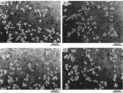
Figure 7 shows that SEM images of microstructures for the hypereutectic Mg-Si alloy treated by application alternating current from different starting temperatures till 630C.
Likewise, the microstructures for these samples consists mainly of primary Mg2Si crystals, eutectic Mg2Si +-Mg
phases and small amounts of -Mg phase. The isolated island-shaped -Mg phase could also be observed in these four samples. Compared with the sample without treatment, the coarse dendritic primary Mg2Si crystals could be hardly
found and the primary Mg2Si crystals were remarkably
refined for these samples treated by application alternating current. However, it could be found that the refined primary Mg2Si crystals agglomerated locally could be observed in the
samples when the starting temperatures of the application
Tungsten electrode
10 20
Al
2O
3tube
Observed
area 15
×
15
Fig. 4 Observed area in the sample (unit: mm).
0 500 550 600 650 700 750 800
0.99 1.03 1.07 1.11 698
699 700 701
Temperature,
T
/
°
C
Time, t / min
1.4 1.6 1.8 2.0 2.2 2.4 620
630 640 650 660
637.7 °C
Temperature,
T
/
°
C
Time, t / min
(a)
Temperature,
T
/
°
C
Time,
t
/ min
4 500
550 600 650 700 750 800
0.78 0.82 0.86 0.90 698
699 700 701
Temperature,
T
/
°
C
Time, t / min
1.2 1.4 1.6 1.8 2.0 620
630 640 650 660
637.6 °C
Temperature,
T
/
°
C
Time, t / min
(b)
Temperature,
T
/
°
C
Time,
t
/ min
4 3
2 1
0 1 2 3
[image:3.595.85.254.68.221.2] [image:3.595.315.541.74.420.2]alternating current were 770 and 740C. As a result, the
refined primary Mg2Si crystals distributed non-uniformly,
as shown in Figs. 7(a) and 7(b). However, for the samples treated by application alternating current at the starting temperature of 700 and 670C, the agglomeration of refined
primary Mg2Si crystals could hardly found and the refined
Mg2Si crystals distributed relatively uniformly, as shown in
Figs. 7(c) and 7(d).
3.3 Statistical analysis results of the sizes of primary
Mg2Si crystals
For every sample, sizes of 200 primary Mg2Si crystals
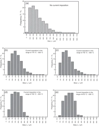
were measured. These 200 data were analyzed by statistical method. The statistical histogram of the primary Mg2Si sizes
are shown in Fig. 8 for the five samples prepared in the present study. In these figures, the size intervals for counting for the sample without treatment by application alternating current and for the samples treated by application alternating current at different temperature ranges are 100mm and 50mm, respectively. The results of statistical average size and standard deviation are listed in Table 1. Also, the total ratios of the numbers of coarse Mg2Si crystals with sizes over than
400mmto the 200 primary Mg2Si crystals measured for all
samples are listed.
Fig. 6 Low magnification (a) and high magnification (b) SEM images of the hypereutectic Mg-Si alloy without application alternating current.
[image:4.595.87.511.73.229.2] [image:4.595.85.511.275.598.2]0 5 10 15 20 25
1600 ~ 1700
(a)
Size, L / 1000 ~ 1100 1100 ~ 1200 1200 ~ 1300 1400 ~ 1500 1500 ~ 1600
900 ~ 1000
800 ~ 900
700 ~ 800
600 ~ 700
500 ~ 600
400 ~ 500
300 ~ 400
200 ~ 300
100 ~ 200
0 ~ 100
Frequency,
F
/ %
No current imposition
0 5 10 15 20 25
(b) Current imposition in the
range of 770 °C ~ 630 °C
Size, L / µm
Frequency, F / % 0 5 10 15 20 25
(c) Current imposition in the
range of 740 °C ~ 630 °C
Size, L /
Frequency, F / % 0 5 10 15 20 25
(d) Current imposition in the range of 700 °C ~ 630 °C
Size, L /
0 ~ 50 50 ~ 100 100 ~ 150 150 ~ 200 200 ~ 250 250 ~ 300
300 ~ 350 350 ~
400 400 ~ 450 450 ~ 500 500 ~ 550 550 ~ 600
600 ~ 650 650 ~
700 Frequency, F / % 0 5 10 15 20 25
(e) Current imposition in the
range of 670 °C ~ 630 °C
Size, L /
Frequency,
F
/ %
µm µm
µm µm 0 ~ 50 50 ~ 100 100 ~ 150 150 ~ 200 200 ~ 250 250 ~ 300
300 ~ 350 350 ~
400 400 ~ 450 450 ~ 500 500 ~ 550 550 ~ 600
600 ~ 650 650 ~
700 0 ~ 50 50 ~ 100 100 ~ 1 50 150 ~ 2 00 200 ~ 2 50 250 ~ 3 00
300 ~ 350 350 ~
4 00 400 ~ 4 50 450 ~ 5 00 500 ~ 550 550 ~ 6 00
600 ~ 650 650 ~
7 00 0 ~ 50 50 ~ 100 100 ~ 150 150 ~ 200 200 ~ 250 250 ~ 300
300 ~ 350 350 ~
400 400 ~ 450 450 ~ 500 500 ~ 550 550 ~ 600
600 ~ 650 650 ~
700
[image:5.595.99.496.72.576.2]Fig. 8 Statistical histogram of the primary Mg2Si crystals size in the hypereutectic Mg-Si alloy without treatment (a) and treated by application alternating current from different starting temperature ((b) 770C, (c) 740C, (d) 700C, (e) 670C) till 630C. The size intervals for counting in (a) and in (b) to (e) are 100mmand 50mm, respectively.
Table 1 Statistical results of the primary Mg2Si size in the hypereutectic Mg-Si alloy treated by application alternating current in the different temperature ranges.
Sample No.
Temperature ranges of application alternating
current
Statistical average size of primary Mg2Si
crystals (mm)
Standard deviation (mm)
Total ratio of the Mg2Si crystals over than 400mm
1 Without treatment 403 240.6 40.0%
2 770C to 630C 202 95.8 4.0%
3 740C to 630C 204 99.5 3.0%
4 700C to 630C 196 68.2 0%
[image:5.595.53.548.689.786.2]For the sample without treatment, the sizes of primary Mg2Si crystals distribute from 50mmto about 1600mmand
mainly locate in the range of 100mmto 700mm. Its statistical average size and standard deviation are 403mm and 240.6mm, respectively. The ratio of the Mg2Si crystals with
sizes over than 1000mmto the 200 crystals measured for this sample amounts to about 3%, which implies there existed some very coarse Mg2Si crystals with complex dendirtic
morphologies (as shown in Fig. 6(b)) in the hypereutectic Mg-Si alloy without application alternating current.
For the samples treated by application alternating current from the starting temperatures of 770 and 740C, the sizes of
primary Mg2Si crystals distribute from 50 to about 650mm
and mainly locate in the range of 50mm to 400mm. The largest size was significantly refined from 1600 to 650mmfor these two samples. Their statistical average sizes and standard deviations are decreased to about 200mm and 98mm, respectively. There are some primary Mg2Si crystals
with sizes over than 400mmexisted in these two samples and their total ratios to the 200 primary Mg2Si crystals measured
are about 4% and 3%, respectively. However, the total ratio of the Mg2Si crystals with sizes over than 400mm to the
200 primary Mg2Si crystals measured amounts to about
40% for the sample without application alternating current. When the starting temperatures of the application alter-nating current was decreased to 700C, the large primary
Mg2Si crystals with sizes over than 400mm could hardly
found in the sample, as shown in Fig. 8(d). The sizes of primary Mg2Si crystals mainly distribute from 50 to about
300mm for this sample. Their statistical average sizes and standard deviations are decreased to 196mm and 68.2mm, respectively. For the sample treated by application alternat-ing current from the startalternat-ing temperatures of 670C, the sizes
of primary Mg2Si crystals mainly distribute from 100mmto
about 350mm. Their statistical average sizes and standard deviations are about 228mmand 72.5mm, respectively. The total ratio of the primary Mg2Si crystals with sizes over than
400mm existed in this sample to the 200 primary Mg2Si
crystals measured is about 1.5%.
From the above results, it is known that primary Mg2Si
crystals could be refined due to the application alternating current for the hypereutectic Mg-Si melt. In particular, the coarse dendritic primary Mg2Si crystals with size above
650mm could be hardly found in the samples treated by application alternating current. The average sizes of primary Mg2Si crystals were decreased almost half for the three
samples treated from the starting temperature of 770, 740 and 700C. However, the standard deviations for the two samples
treated from the higher starting temperature of 770 and 740C are higher than that of sample treated from the starting
temperature of 700C. For the sample treated from the lower
starting temperature of 670C, its average size increased
slightly but its standard deviation was low.
Based on the above results, a conclusion could be drawn that primary Mg2Si crystals in the hypereutectic Mg-Si alloys
could be refined effectively by application alternating current. The starting temperature of the application alternat-ing current is a very significant factor to determine the size uniformity of primary Mg2Si crystals, while it has no obvious
effect on the average size primary Mg2Si crystals. From the
viewpoint of modification effect, the optimal starting temper-ature is 700C, at which primary Mg
2Si crystals have the
lowest average size and the highest uniformity in sizes with the lowest standard deviation.
4. Discussion
4.1 Effect factors on the cooing history
Cooling history is an important factor to determine the microstructural evolution for a metal product. In order to realize the effect of the application alternating current on solidified structures of the hypereutectic Mg-Si alloy, it is essential to reckon the effect resulting from the differences in cooling rates after the alternating current was applied into the melt. When the alternating current,Jwith frequency 1 kHz is applied, an alternating magnetic field, B with the same frequency can be induced in the melt. This alternating magnetic field interacts with the electric current itself and induces an alternating electromagnetic vibration in the melt. Compared with the sample without alternating current treatment, the cooling histories for the samples treated by application alternating current could be influenced by another two factors. One factor is that joule heat generated in the sample will result in a decrease in cooling rate. The slight rise of temperature after application of alternating current (shown in Fig. 5(b)) should be the result of joule heat generation. The same phenomenon could not be found for the sample without application alternating current, as shown in Fig. 5(a). Another factor is the electromagnetic vibration, which can improve the transfer of heat to surrounding walls by forced convection, which will increase the cooling rate. It can be deduced that the effects of the above two factors on the cooling rate could counteract because the cooling rates were almost same for all samples. Therefore, the effect of cooling rate on the microstructures for the hypereutectic Mg-Si alloys could be excluded in the present study.
4.2 Microstructural evolution of hypereutectic Mg-Si
alloys
According to the Mg-Si binary alloy phase diagram,28)as shown in Fig. 2, the Mg-4.8 mass% Si alloy is a typical hypereutectic alloy. If the cooling rate is sufficiently low, its solidification path is along a near equilibrium route. Consequently, its microstructure should consist of two constituents: primary Mg2Si crystals and (Mg+Mg2Si)
eutectic crystals. However, when the cooling rate is high, such as in the case of present experimental condition, solidification path is along a non-equilibrium route. After primary Mg2Si crystals form, Mg will subsequently
precip-itate and grow as sub-primary crystals prior to the final eutectic reaction in the rest of the melt.29)
In the present experimental conditions, the primary Mg2Si
crystals began to nucleate and grow in the hypereutectic Mg-Si melt after the temperature decreased to less than 761C. In the studies performed by Ourfaliet al.30)and Qin et al.31) It was found that the morphologies of the primary Mg2Si crystals would change from coarse equiaxed to
dendritic with the cooling rate increasing to exceed a critical velocity. For the Mg2Si crystal, its structure belongs to face
the preferential [1 0 0] crystallographic directions.31,32) For the sample without alternating current treatment, the mor-phologies of the primary Mg2Si crystals are mainly
charac-terized by dendrites (shown in Fig. 6), which implies that the solidification cooling rate in the present study is above the critical velocity as reported by Ourfaliet al.30)and Qin et al.31)Moreover, based on the solidification theory,33)it can be reasonably inferred that some new Mg2Si crystals should
nucleate from the melt during the growth of Mg2Si crystals
nucleated initially with the decrease of temperature. Com-pared with the precipitated Mg2Si crystals at higher
temper-atures, these Mg2Si crystals precipitated at lower
temper-atures can not grow into coarse dendritic morphologies due to no enough time before solidifying fully. Therefore, in addition to coarse Mg2Si crystals with complex dendritic
morphologies, there are also some polygonal Mg2Si crystals
in the hypereutectic Mg-Si alloys without alternating current treatment, as shown in Fig. 6.
As primary Mg2Si crystals continuously grow, the liquid
phase surrounding them becomes enriched with Mg due to the rejection of Mg solute atoms under the condition of high solidification cooling rate. When the local concentration of Mg solute is sufficient, the growth of Mg2Si crystals will
be limited and Mg will nucleate on the Mg2Si facets and
grow.29) Consequently, Mg sub-primary crystals could be formed as halos surrounding Mg2Si primary crystals. In
addition to -Mg halos, the isolated island shaped -Mg phase could obviously observed in the present study, as shown in Figs. 6 and 7. It is difficult to explain clearly the formation of the isolated island shaped-Mg phase. Based on the solidification theory,33)it is possible that the real eutectic composition deviates the equilibrium eutectic composition under high solidification cooling rate. If the silicon concen-tration in the rest of Mg-Si melt is less than the real eutectic composition, the isolated island shaped-Mg phase can form before the eutectic reaction occurs. Lastly, the Mg-Mg2Si
eutectic phases form in the rest of the melt. Consequently, under the present study, the microstructures consist of three consequents, as shown in Figs. 6 and 7.
4.3 Modification effect of the application alternating
current
It is well known that when an alternating current with high frequency was applied into the melt, a vibrating electro-magnetic body force could be induced in the liquid melt.24–27) In the present study, when the alternating current was applied into the hypereutectic Mg-Si melt at high temperatures of 770C and 740C, it was interesting that obvious
agglomer-ations of refined Mg2Si crystals occurred in these two
samples and the Mg2Si crystals distributed non-uniformly, as
shown in Figs. 7(a) and 7(b). In the Radjai’s study,20) the agglomeration of primary Si crystals in the hypereutectic Al-Si melt treated by electromagnetic vibration was found. The Si crystals refined to a specific size is a necessary condition for this phenomenon to occur, i.e. only the refined Si crystals with sizes less than the specific size agglomerate locally.20)
Up to now, it is difficult to explain clearly why the agglomerations of Mg2Si crystals occur after the
hyper-eutectic Mg-Si melt was treated by application alternating current at the high temperatures. This phenomenon will be
further investigated and reported. However, it is possible that the small sizes of Mg2Si crystals precipitated in the initial
stage of solidification should be responsible for the agglom-eration of Mg2Si crystals. In the initial stage of solidification,
the mass fraction of the primary Mg2Si crystals is low and the
sizes should be small. These small Mg2Si crystals should be
easy to vibrate with the melt which was subjected to an electromagnetic vibration. Figure 9 shows the theoretical mass fraction of the primary Mg2Si crystals precipitated from
the hypereutectic Mg-4.8 mass%Si melt changes with the temperature under the equilibrium condition of solidification. For example, the theoretical mass fraction of the primary Mg2Si crystals is only 2.6 mass% at the temperature of
740C.
With the decrease in the solidified temperature to 700C,
the theoretical mass faction of Mg2Si crystals in the
hyper-eutectic Mg-4.8 mass%Si melt increase to about 6.1 mass% from 2.6 mass% at the 740C, as shown in Fig. 9. Also, some
Mg2Si crystals precipitated in the initial solidification stage
should grow to coarse crystals with complex dendritic morphologies. Under these conditions, the oscillatory motion of Mg2Si crystals will become difficult due to large sizes.
Therefore, no obvious agglomerations of the Mg2Si crystals
were found in the samples treated by application alternating current from starting temperatures of 700 and 670C.
Usually, it is widely accepted that the refinement of the structures caused by EMV attributes to the fragmentation by mechanical stress and by the re-melting of the primary solid phase due to constitutional undercooling.26,27)For the latter, it is not necessary to think of the bonding among atoms. For the former, the present authors think that the dendritic Mg2Si
crystals were fragmented from some weak parts subjected to the EMV. In this case, a strong mechanical force would be required for breaking the dendritic Mg2Si crystals because
chemical bonding of an intermetallic compound is generally combination of covalent bond and metallic bond. Therefore, further investigation is required to clarify the detail of the refinement mechanism.
For the dendritic crystals, the weak parts should be the root regions where secondary dendrites grow from primary trunk of dendrites or third dendrites grow from the trunk
630 650 670 690 710 730 750 770
0 2 4 6 8 10
740
°
C
700
°
C
670
°
C
2.6 6.1
8.2
Mass fraction of the primary Mg
2
Si, mass%
Temperature, T /
°
C
[image:7.595.320.532.72.240.2]of secondary dendrites.30) These root regions will become smaller gradually because the melting point will decrease due to the enrichment of solutes rejected from the surfaces of the dendrites. These weak root regions were named as ‘‘shrink-age neck’’.33)These broken Mg
2Si crystals with small sizes
can also move with the melt. However, the oscillatory motion of the broken Mg2Si crystals is difficult due to the high
content of the Mg2Si crystals in the melt and low
temper-atures, which can avoid the formation of agglomeration, resulting in distribution uniformly in the sample.
As for the agglomerations of the refined primary Mg2Si
crystals was concerned, it has been deeply discussed and reported in another study.34)After the refined primary Mg2Si
crystals agglomerated, the electrical conductivity at the regions containing Mg2Si crystals would become low
because the electrical conductivity of Mg2Si crystal might
be small than that of the melt.32) Therefore, the actual alternating current density passing through these regions should be less than that passing through the liquid melt. Consequently, the primary Mg2Si crystals existed in the
agglomerated regions could not be effectively broken. As for the sample treated from the starting temperature of 670C, no enough time could be provided to effectively
modify some primary dendritic Mg2Si crystals before the
melt was fully solidified. This might be the reason why the refined primary Mg2Si crystals have the lowest average size
and the highest size uniformity for the sample treated from the starting temperature of 700C.
5. Conclusions
(1) Application alternating current has no obvious effect on the cooling history and eutectic temperature during solidification for the hypereutectic Mg-Si alloys. Be-sides primary Mg2Si crystals and eutectic Mg2Si +
-Mg phases, its microstructures consist small amounts of
-Mg phase, including-Mg halos and isolated island-shaped-Mg phase. The-Mg phase are surrounded by the eutectic structure of Mg2Si +-Mg phases.
(2) Primary Mg2Si crystals in the hypereutectic Mg-Si
alloys could be refined effectively by application alternating current. The average sizes of primary Mg2Si
crystals were decreased to almost a half after being subjected to the alternating current.
(3) The starting temperature of the application alternating current is a very significant factor to determine the size uniformity of the primary Mg2Si crystals, while it has
no obvious effect on the average size primary Mg2Si
crystals. The refined primary Mg2Si crystals have the
lowest average size and the highest size uniformity when the starting temperature was 700C.
Acknowledgement
This work was partially supported by JSPS Asian Core Program ‘‘Construction of the World Center on
Electro-magnetic Processing of Materials’’, and Natural Science Foundation of Guangdong Province, China (Contract No. 05300139).
REFERENCES
1) B. L. Mordike and T. Ebert: Mater. Sci. Eng. A302(2001) 37–45. 2) H. Dieringa and K. U. Kainer: Materialwissenschaft und
Werkstoff-technik38(2007) 91–96.
3) A. A. Luo: Inter. Mater. Rev.49(2004) 13–30.
4) J. Bai, Y. S. Sun, S. Xun, F. Xue and T. B. Zhu: Mater. Sci. Eng. A419 (2006) 181–188.
5) K. J. Hirai, H. T. Somekawa, Y. N. Takigawa and K. J. Higashi: Mater. Sci. Eng. A403(2005) 276–280.
6) S. M. Zhu, M. A. Gibson, J. F. Nie, M. A. Easton and T. B. Abbott: Scr. Mater.586(2008) 477–480.
7) C. J. Boehlert: J. Mater. Sci.42(2007) 3675–3684. 8) P. Zhang: Scr. Mater.52(2005) 277–282.
9) D. J. Kang, S. S. Park, Y. S. Oh and N. J. Kim: Mater. Sci. Eng. A 449–451(2007) 318–321.
10) R. Tsuzuki, K. Kondoh, W. B. Du, T. Aizawa and E. Yuasa: Mater. Sci. Forum419–422(2003) 789–794.
11) M. Mabuchi, K. Kubota and K. Higashi: J. Mater. Sci.31(1996) 1529– 1535.
12) M. Mabuchi, K. Kubota and K. Higashi: Scr. Metall. Mater.33(1995) 331–335.
13) L. Lu, K. K. Thong and M. Gupta: Comp. Sci. Tech.63(2003) 627– 632.
14) Q. C. Jiang, H. Y. Wang, Y. Wang, B. X. Ma and J. G. Wang: Mater. Sci. Eng. A392(2005) 130–135.
15) H. Y. Wang, Q. C. Jiang, B. X. Ma, Y. Wang, J. G. Wang and J. B. Li: J. Alloy. Compd.387(2005) 105–108.
16) S. J. Guo, Q. C. Le, Z. H. Zhao, Z. J. Wang and J. Z. Cui: Mater. Sci. Eng. A404(2005) 323–329.
17) S. J. Guo, Q. C. Le, Y. Han, Z. H. Zhao and J. Z. Cui: Metall. Mater. Trans.37A(2006) 3715–3724.
18) Y. Mizutani, T. Tamura and K. Miwa: Mater. Sci. Eng. A413–414 (2005) 205–210.
19) C. Vives: J. Crystal Growth173(1997) 541–549.
20) A. Radjai, K. Miwa and T. Nishio: Metall. Mater. Trans.29A(1998) 1477–1484.
21) Y. Mizutani, S. Kawai, K. Miwa, K. Yasue, T. Tamura and Y. Sakaguchi: Mater. Trans.45(2004) 1939–1943.
22) F. C. R. Hernandez and J. H. Sokolowski: J. Alloy. Compd.426(2006) 205–212.
23) T. Takaki, K. Iwai and S. Asai: ISIJ Int.43(2003) 842–848. 24) M. Usui, K. Iwai and S. Asai: ISIJ Int.47(2007) 1571–1574. 25) M. Usui, K. Iwai and S. Asai: ISIJ Int.47(2007) 1613–1617. 26) K. Sugiura and K. Iwai: ISIJ Int.45(2005) 962–966. 27) M. J. Li: ISIJ Int.48(2008) 320–329.
28) T. B. Massalski, J. L. Murray, L. H. Bennett and H. Baker: Binary alloy phase diagrams, Metals Park, Ohio, (American Society for Metals, 1986) p. 1545.
29) Y. C. Pan, X. F. Liu and H. Yang: Mater. Charact.55(2005) 241– 247.
30) M. F. Ourfali, I. Todd and H. Jones: Metall. Mater. Trans.36A(2005) 1368–1372.
31) Q. D. Qin, Y. G. Zhao, W. Zhou and P. J. Cong: Mater. Sci. Eng. A447 (2007) 186–191.
32) E. E. Schmid, K. V. Oldenburg and G. Frommeyer: Z. Metallkde.81 (1990) 809–815.
33) Q. C. Li: Principles of casting formation, (Mechanical Industry Press, 1989) pp. 94–155.