A Thesis Submitted for the Degree of PhD at the University of Warwick
Permanent WRAP URL:
http://wrap.warwick.ac.uk/106904/
Copyright and reuse:
This thesis is made available online and is protected by original copyright.
Please scroll down to view the document itself.
Please refer to the repository record for this item for information to help you to cite it.
Our policy information is available from the repository home page.
A Non-determ/n/stfc Approach to Dynamfc Layout P/ann/ng
ofFUeadbfeManufacturing Systems
A th esis su bm itted fo r th e d eg ree o f D o c to r o f Ph ilosoph y in th e D epartm ent o f E n g in eer^ U n iversity o f W arwick
By
S .P.H atam i K hosrow shahi B .S c., At.Sc.
The U n iversity o f W arwick
ACKNQWLEPQEMENTS
The author w i s h e s to thank D r .T .C .Go o d h e a d for his
c o n t i n u o u s supervision, gu i dance and e n c o u r a g e m e n t dur i n g
the c ou r s e of this r e se a r c h work.
The author w o u l d a l s o like to e x p r e s s his th a n k s to
D r . S . G r i n s t e d for her help in m o d i f i c a t i o n of the s o f t w a r e
use d in this research.
F i n a l l y the auth o r w i s h e s to thank his p a re n t s and family
for t heir patience and c o n st a n t e n c o u r a g e m e n t t h r o u g h o u t
ABSTRACT
A new a p p r o a c h to the d y n a m i c layout p l a n n i n g p r o b l e m is pr oposed which pro v i d e s solu t io n s t o hi g hl y v a r i a b l e material flow patt e r n s oc c u r r i n g o v e r a m u l t i - p e r i o d pl anning horizon and is e s p e c i a l l y s u i t a b l e for f l e x i b l e m a n u f a c t u r i n g systems. A n o n - d e t e r m i n i s t i c e n v i r o n m e n t is c o n s i d e r e d in which t here is assumed to be u n c e r t a i n t y in the future material f low data. The p e r f o r m a n c e of the met hod is assesse d by c o m p a r i ng the s ol u ti o n p r o d u c e d by this met h o d w it h a set of d a t a p r o vided in the li terature for which th e c l a im e d optimal s o l u t i o n is known. There is c lose a g r e e m e n t w i t h the s t a t e d s ol u ti o n a n d the result is o b t a i n e d wi t h a fraction of the c o m p u t a t i o n a l effort.
The computational e f f i c i e n c y is due to a new c o n s t r u c t i o n method to generate s ta t i c layout solu ti o n s . This m e t h o d uses an a l g o r i t h m in w h i c h the n u m b e r of s t a g e s is proportional to the n um b e r of f a c i l i t i e s rather t h a n an exponentional relat i o n s h i p as found in m o s t other m e t hods. The m e t h o d also uses an e l e m e n t of f o r w a r d p l a n n i n g to ensu re that early lo c ation a s s i g n m e n t s p r ov i de m i n i m u m r e s t riction to a s s i g n m e n t s made later in th e procedure.
Results of e x t e n s i v e t ests s how that the ne w st a t i c layout planning pr o c e d u r e p r o d u c e s solu t io n s g e n e r a l l y b e t t e r t h a n exi sting c o n s t r u c t i o n t e c h n i q u e s and c o m p a r a b l e w i t h im pro vement techn i q u e s such as CRAFT. T h e e x e c u t i o n s p e e d of the p r o c e d u r e m a k e s it p o ssible to s o l v e large s c a l e prob l e m s ( >30 )in very short time s ca l e s on M i c r o c o m puters .
C O N T E NT
C H AP TER O N E PAGE
1.1 P r o b l e m S t a t e m e n t 1
1.2 Flexibl e M a n u f a c t u r i n g Syst e ms 6 1.2.1 P r o d u c t i o n S y s t e m A r r a n g e m e n t s 7
1.3 Material H a n d l i n g S y s t e m s 9
1.4 Facil i t i e s L a y o u t T ec h n i q u e s 12 1.4.1 Stat i c and D y n a m i c Layout Pl a nning 13
C H APT ER TWO
STATIC LAY O U T PLAN N I N G
2.1 I n t r o d u c t i o n 20
2.1.1 D i s t a n c e M e a s u r e m e n t 24
2 . 1 . 2 Model V a l i d i t y 26
2 . 1 . 3 Steps of La y ou t De s i g n Process 26
2.2 Static Layout P l a n n i n g 29
2.2.1 Trad i tional A p p r o a c h e s to SLP 29
2 . 2 . 2 Analytical and C o m p u t e r i z e d
T e c h n i q u e s f or SLP 43
2.3 D y nami c Lay o u t P l a n n i n g 45
2.3.1 D y na m i c La yo u t P l an n i n g P r ob l e m 45 2 . 3 . 2 Exist i ng S o l u t i o n P r ocedures 48
C H A P T E R T H R E E
Q U A D R A T I C A S S I G N M E N T P R O B L E M
3.1 I n t r o d u c t i o n 54
3.2 F o r m u l a t i o n of F a c il i t i e s Layout
P l a n n i n g (F L P ) as Q A P 54
3.2.1 A s s i g n m e n t of n F a c i li t ie s to n
Lo c a t i o n s w i t h no A l l oc a t i o n Cost 56 3 .2.2 I n c o r p o r a t i o n of A l l o c a t i o n Cost
to the F o r m u l a t i o n 58
3.3 A p p l i c a b i l i t y of the QAP in Layout
P l a n n i n g A s p e c t of FMS 58
3.4 Existin g S o l u t i o n P r o c e d u r e s for QAP 63
3.4.1 C o m p l e x i t y of the Q A P 63
A C K N O W L E D G E M E N T S
The auth o r w i s h e s to t h a n k D r .T .C .G o o d h e a d f o r his
c o n t in u ou s supe r v i s i o n , g u i d a n c e and e n c o u r a g e m e n t during
the course of this r e s earch work.
The author w o u l d a l s o like to express his t h a n k s to
D r . S . G r i n s t e d for her help in m o d i f i c a t i o n of the s o ft w a r e
used in this research.
Finally the a u t h o r w i s h e s to t hank his p a r e n ts and family
for their p a t i e n c e and c o n s t a n t e n c o u r a g e m e n t t h r o u g h o u t
the du r a t io n of this work.
ABSTRACT
A new a p p r o a c h to the d y n a m i c layout p la n ni n g p r o b l e m is p rop osed w h i c h provides sol ut i on s to highly v a r i a b l e material f l o w patterns o c c u r r in g over a m u l t i - p e r i o d pl annin g ho r i z o n and is e s p e c i a l l y s ui t a b le for fl e x i b l e m a n u f a c t u r i n g systems. A n o n - d e t e r m i n i s t i c e n v i r o n m e n t is c o n s i d e r e d in which there is assumed to be un c e r t a i n t y in the fut u r e material flow data. The p e r f o r m an c e of the me t h o d is assessed by co m p ar i ng the s o lution pr o d u c e d
by this method with a set of data pr o vided in the
l it eratu re for which the c l a i m e d optimal s ol u t i on is known. There is c l o s e agreement w i t h the stated s o l ution and the result is obtained with a f ra c t i on of the c o mp utational effort.
The computational e f f i c i e n c y is due to a new c o n s t r u c t i o n m e t h o d t o generate stati c layout solutions. Thi s me t h o d uses an a l g o r i t h m in w h i c h the number of sta g es is
propo rti onal to the number of f a cilities rather tha n an
e x p o n e n t i o n a l relationship as found in m o s t other methods. The m et h o d also uses an e l e m e n t of forw a rd p l a n n i n g to e n s u r e t h a t early location as s i g n m e n t s provi d e m i n i m u m r es t r i c t i o n to assignments m a d e later in the procedure.
R esu lts of ex t e n s i v e tests s h o w that the new static layout p lan ning p r o c e d u r e produce s s o l ut i o n s ge nerally b e t t e r than ex is t i n g const r u c t i o n t e c hn i qu e s and c o m pa r a b l e with imp r o v e m e n t t e chniques such as CRAFT. The e x e c u t i o n speed of the p r o c e d u r e m akes it p os sible to s olve large scale pr ob l e m s ( >30 )1n very s h or t time scales on M i c r o co m p u t e r s .
I n c o r p o r a t i o n of the fast n e w con s tr u ct i o n m e t h o d into dy n a m i c layout planning al lo w s decision mak i n g c on c e r n i n g whe n and h o w to re-layout f a c i l it i es in response to changes in p r e d i c t e d material flow.
SQMTENT
C H A PT E R QNE p a g e
INTRO DUCTI ON
1.1 P r oblem S t a t e m e n t 1
1.2 Flexible M a n u f a c t u r i n g S y s t e m s 6 1.2.1 P r o d u c t i o n S y s t e m A r r a n g e m e n t s 7
1.3 Material H a n d l i n g Syste m s 9
1.4 F a c i l i t i e s Lay o u t T e c h n i q u e s 12 1.4.1 Static and D y n a m i c Layout P l a n n i n g 13
CH A P T E R TWO
S T A T I C LAYOUT PLANNING
2.1 I n t r o d u c t i o n 20
2.1.1 D i s t a n c e M e a s u r e m e n t 24
2.1.2 Model V a l i d i t y 26
2 . 1 . 3 Steps of La y ou t Design P r o c e s s 26
2.2 Static L a y o u t P la n ni n g 29
2.2.1 T r a d i tiona l A p p r o a c h e s to SLP 29 2 .2.2 A nalytical and C o m p u t e r i z e d
T e c h n i q u e s for SLP 43
2.3 Dynamic L a y o u t Pl a n n in g 45
2.3.1 D y namic La y o u t P l a n ni n g P r o b l e m 45 2 .3.2 Exis t i n g S o lu t i o n P r o c e d u r e s 48
C H A P T E R THREE
Q U A D R A T I C A S S I G N M E N T P R O B L E M
3.1 I n t r o d u c t i o n 54
3.2 F o r m u l a t i o n of F a c i l it i es Layout
Planning (F L P ) as Q A P 54
3.2.1 A s s i g n m e n t of n F a c i l i t i e s to n
Loc a t i o n s w ith no A l l o c a t i o n Cost 56 3.2.2 I n c o r p o r a t i o n of A l l o c a t i o n Cost
to the F o r m u l a t i o n 58
3.3 A p p l i c a b i l i t y of the Q A P in Layout
Planning A s p e c t of FMS 58
3.4 Existing S o l u t i o n P r oc e d u re s for Q AP 63
3.4.1 C o m p l e x i t y of the Q A P 63
3.4.3 H e u ristic A p pr o a c h e s to th e QAP 68
3.5 A l t e r n a t i v e A p p r o a c h e s to the Q A P for
For m u l a t i n g F L P 69
C H A P T E R FOUR
A N E W S O LUTION TO THE S T A T I C LAYOUT P L AN N I N G PROBLEM - THE I N IT IAL LA YOUT GEN E R A T O R
4.1 Introd u c t i o n 74
4.2 A New C o n s t r u c t i o n Te c h n i q u e for G e n e r a t i n g N e a r Optimal Solu t io n
-The Initial La y o u t G e nerator (ILG) 74
4.2.1 Formation o f the Link Table 80
4.2.2 The S e l e c t i o n P r ocedure 81
4 .2.3 The A l l o c a t i o n Procedure 84
4.3 D a t a M o d i f i c a t i o n of N o n - Sq u ar e
Facil i t i e s 86
4.4 Illust r a t i v e E x a m p l e s 89
4.4.1 A M a n u f a c t u r i n g System w i t h 20
eq u a l l y s i z e d fa cilities 90
4.4.2 A M a n u f a c t u r i n g System w i t h 8
f acilities o f dif f er e nt sizes 99
C H A P T E R FIVE
E V A L U A T I O N OF THE ILG P E R F O R M A N C E
5.1 I n t r o d u c t i o n 108
5.2 Des c r i p t i o n of MAT Procedure 110
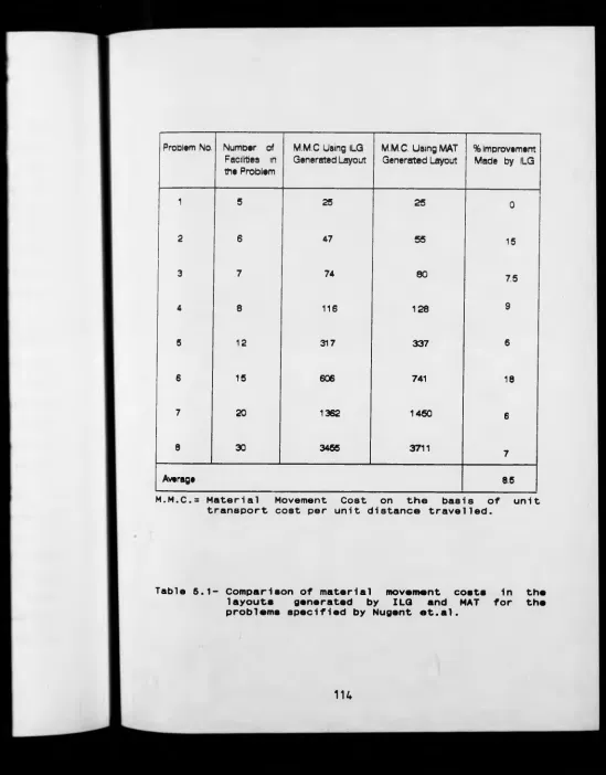
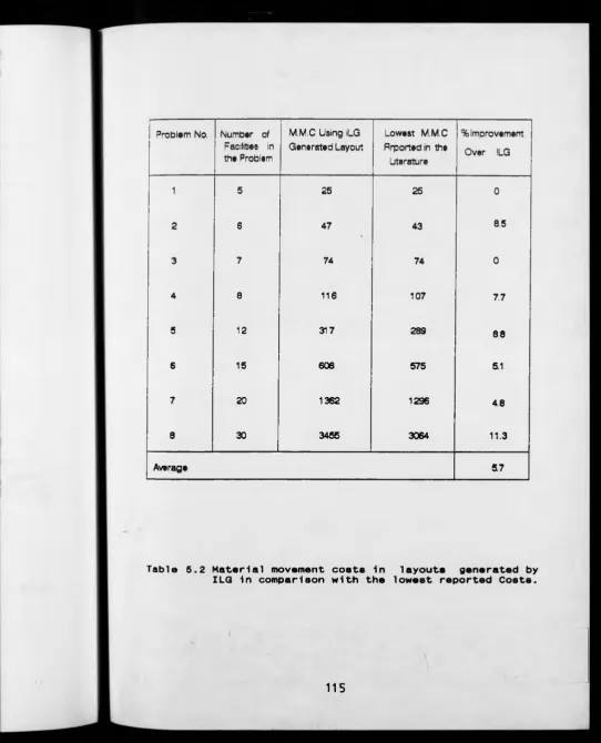
5.3 T e s t s and R e s u l t s 112
5.3.1 T ests P e r f o r m e d on Problems
O r i g i n a t e d by Nugent et.al. 112
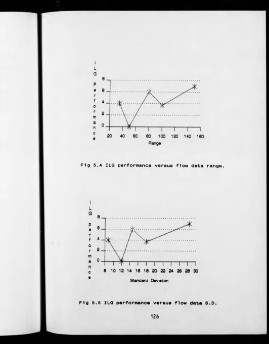
5.3.2 I n v e s t i g a t i o n into the R e l ation b e tween ILG and C ha r a c t e r i s t i c s
of the ma t erial flow m at r i c e s 124
C H A P T E R SIX
A- NSW N Q N - P E T E R M I N I S T I C A P P R O A C H TO DYNAMIC LAYOUT PL A NNING
6.1 Intro d u c t i o n 127
6.2 Exis t i n g DLP Proce d u r es and Their
S h o r t c o m i n g s 128
6.2.1 D y n a m i c P r o g r a m m i n g A p p r oa c h to
the Layout P r o b l e m 128
6.2.1.1 C o m p u t at i on a l Feasibility of
Dynamic P r o g r a m m i n g 134
Layout Plann i n g o f FMSs 140
6.3 A New App roach to D y n am i c La yo u t
Plan n i n g of F a c i l i t i e s for FMSs 143
6.3.1 F o r m u lation of DLP P r o b l e m 147
6.3.2 Esta b l i s h m e n t of T im e P e r i o d s 150
6.3.3 A Numerical Example 152
6.3.3.1 The R e p r e s e n t a t i v e P r o b l e m 152
6. 3 . 3 . 2 P r oblem Solution 156
C H A P T E R SEVEN D I S C U S S I O N
7.1 I n t r o d u c t i o n 169
7.2 E v a l u a t i o n of ILG in G en e r a ti n g S o l u t i o n s for the S t a t i c Layout
P r o b l e m 169
7.2.1 ILG Q u a l i t y 170
7.2.2 ILG Speed 175
7.2.3 ILG Appl i c a b i l i t y 176
7.3 D i f f e r e n c e s Ob s er v e d in the S ol u t i on
to the problems in t h e literature 180
7.4 D i s c u s s i o n of the P r o p o s e d DLP M e t h o d 181
7.4.1 Benefits of C o p i n g with
Non-d e t e r m i n i s t i c and U p -d a te d Data 181 7.4.2 C o n s i d e r a t i o n of "Time V a l ue of
M o n e y " i n Solution o f M ul t i - p e r i o d
Layout Probl e m 181
7.4.3 Sen s i t i v i t y of the P r o p o s e d D y n am i c Met h o d to the F o r e c a s t Flow Mat ri x
Data 182
CHAPTER EIGHT
C O N C L U S I O N 1S6
R E F E R E N C E S 190
A P P E N D I C E S
A - W i m m e r t ’s Method. A-1
B - Sw e e n e y and T a t h a m s ’s Theorem. B-1
C - Material Flow Data and Plant
Shapes for the N u g e n t ’s Problems. C-1
D - ILG Solution A s s i g n m e n t s to the
E Initial Sol u t io n s
P r o b l e m s . for N u g e n t ’s
E-F - U p - D a t a e d E-F r om - T o M a tr i c e s for
Example in C h a p te r Six.
F-G - C o m p a r i s o n of Material Flow C o s t s Re s u l t i n g fro m S o l u t i on s P r o d u c e d by CRAFT Sta rting w i t h R a n d o m and
ILG Ge n e r a t e d Initial Layouts.
G-H - Dif f e r e n c e s O b s e r v e d in R a n d o m Solu t i o n Co s ts to the N u g e n t ’s
Probl e m s R e p o r t e d in the
Liter a t u r e and O b t a i n e d by M i c r o -
H-CHAPTER ONE
INTRO D U C T I O N
1.1 P r o b l e m S t a t e m e n t
S h i f t i n g ma rket d e m a n d p at te r n and f r e quent f l u c t u a t i o n in
p r o d u c t i o n output level to ge t h e r with v a r i a t i o n in p r o d u c t
mix a n d design has c r e a t e d the requirement fo r responsive
f l e x i b l e m a n u f a c t u r i n g sy s t e m s (FMS).
F l e x i b i l i t y inherent in the e l e m en t s of FMSs, s u c h as
C o m p u t e r Numerical Control (CNC) machi n e s a n d Aut o m a t e d
G u i d e d Vehicles (AGV), may well cope w ith v a r i a t i o n s of
p ar ts produced (either in q u a n t i t y or in d e s ign), si m p l y by
r e p r o g r a m m i n g these elements. But r e p r o g r a m m i n g the
a u t o m a t e d elements of FMS doe s not n e c e s s a r i l y gu a rantee
the e f f i c i e n c y of p r o d u c t i o n of the total system. A part
from e f f e c t i v e u t i l i z a t i o n of f acilities 1n produ c t i o n
systems, the way 1n w h i c h f ac i l i ti e s are laid out and
lo c a t e d relative t o each other is a key factor in
a c h i e v i n g system e f f i c i e n c y and e co n o m i c production.
H a r m o n i o u s a l l o c a t i o n of f a c i l i t i e s 1n the layout and
e n s u r i n g the a d j a c e n c y or n e a rn e ss of f a c i l i t i e s (1n the
s y s t e m layout) with high v o l u m e of parts f l o w between
them, 1s the most c o m m o n l y e x e r c i s e d way, 1n industry, of
r e d u c i n g material h a n d l i n g r eq u irements. This in turn has
the b e n efi t of reduction in material h a nd l i n g costs.
T h e r e f o r e one of the f a ctor s i nf l u e n c i n g the total cost of
m a n u f a c t u r e is tha t of material h a n dl i n g c o s t and
thi s is f u n d a m e n t a l l y linked to the layout of facilities.
To m a i n t a i n their c o m p e t i t i v e n e s s , co m p a n i e s e m p l o y i n g
FMSs have to keep m a n u f a c t u r i n g c o s t to a minimum, w h i l e
b e i n g able to respond to the c h a n g e s m e n t i o n e d earlier.
Thi s implies that the layout of f a c i l i t i e s sh o u l d be
c o n t i n u o u s l y reviewed.
C o n t i n u o u s e v a l u a t i o n of layout, g e n e r al l y t er m e d as
D y n a m i c Layout P l a n n i n g (D L P ) in the literature,
[ M o o r e ( 19 7 4 ) , R o s e n b l a t t ( 1986), A f e n t a k i s ( 1990)], has been
s u g g e s t e d as a means of m a i n t a i n i n g e f f i c i e n c y in batch
p r o d u c t i o n systems w h e r e pa r t m i x / d e s i g n and p r o d u c t i o n
c h a n g e s are regularly introduced.
S i n c e the o c c u r r e n c e of f r e q u e n t c h a n g e is a feat u r e
of F M S ’s, 1t is clea r tha t c o n s i d e r a t i o n of the
c o n f i g u r a t i o n of m a c h i n e s is of g r e a t i mportance for FMSs
e v e r y time material flo w ch a n g e s are n e c e s s a r y t o satisfy
the m a r k e t demand.
DLP, has been de v e l o p e d f r o m Sta t ic L a y o u t P l a n n i n g (SLP)
plann ing periods within the total p l an n in g horizon.
This are a is h o wever relatively n e w and has raised o t h e r
qu e s t i o n s which hav e not yet b een fully investigated.
These q u e s t i o n s can be c a t e g o r i s e d as follows:
* What are t h e
the practical o p t i m u m
dynamic s i t u a t i o n ?
c r i t e r i a for p l a n n i n g
fa c i l it y layout in t h e
* If one o f the c r i t e r i a is
m i n i m i z a t i o n of m a te r ia l m o v e m e n t cost, w h a t
c o n s i d e r a t i o n s are g i v e n to thi s cost if there is
a need to change the initial layout in order to
cope with v a r iat io n in p r o d uc t mix and d e s i g n ?
* How sh o u ld the length of the t i m e
periods between w hi c h r e - l a y o u t s are c o n s i d e r e d
be determined?
* Is t h er e a n y way in w hich r e - l a y o u t
can be delayed?
* If r e - l a y o u t is d e c i d e d upon at th e
end of a time p e r i o d s ho u l d the n e w
p h a s e d manner? i.e. e x a c t l y w hen to
in s t i g a t e the layout.
In addition to the above q u e s t i o n s t h e r e also ex i s t s the
p r ob lem of u n c e r t a i n t y in the d ata r e g a rd i n g f ut u r e prod u c t
volume and the m i x of p r o d u c t d e s i g n to be produced. Many
c o m pan ies e m p l o y i n g FMSs do so b e c a us e of the v o l a t i l e
nature of the mar k e t in w h i c h t he y o p e r a t e and they may
com mon ly e x p e r i e n c e the c a n c e l l a t i o n of or d er s they have
p r e v i o u s l y received, or a l t e r n a t i v e l y receive or d e r s
unexp e c t e d l y w h i c h they c o u l d not have a n t i c ip a t e d
accur a t e l y in advance. T h e r e f o r e ignor i n g the e f f e c t s of
u n c ert ain f ut u r e data on the f a c i l i t i e s layout can lead
to u ndesi rab le a n d costly conseq u e n ce s .
The p rob lem of d y namic layout p l a n n i n g (DLP), in the FMS
context, can be stated b r i ef l y as i n v o l vi n g the f o l l o w i n g
ele m e n t s w hich are additional to t ho s e a d d r e s s e d in
’c o n v e n t i o n a l ’ DLP:,
(i) d e t e r m i n a t i o n of tim e p e r i o d s w i t h i n
the pl anning ho r i z o n in w h i c h re- l a y ou t will be
n e c es sary to m a i n t a i n s y s t e m effici en c y ,
(ii) c o n s i d e r a t i o n in a d v a n c e of f o re c a s t
da t a of u n known accuracy, and Its impact on the m u l t i
In all exis t i n g solu t i o n p r o c e d u r e s to the D L P prob l em none
takes a c c o u n t of both of the a b o v e aspects. In some of the
approaches, for example, c h a n g e s in ma t e r ia l flow data
are as s u m e d to occur at f i x e d time periods, w hile a
t o t all y d e t e r m i n i s t i c view of p r o d u c t design and
p r o d u c t i o n volume is c o n s i d e r e d w i t h i n these time
p eri ods ( R o s e n b l a t t ( 1986)). O t h e r a p p r o a c h e s in which
some limited var i a b i l i t y is t o l e r a t e d in the data, are only
a p p l i c a b l e to systems c o n t a i n i n g a small number of
f a c i 1 i t i e s .
A fu r t h e r sig n i f i c a n t p r o b l e m w i t h e x i s t i n g s ol utions is
the c o n s t r a i n t on p r o b l e m size. This a r i s e s due to an
exponent ial increase in s o l u t i o n tim e wit h th e increase in
the nu m b e r of facilities. Full s o l u t i o n s to probl e m s
c o n t a i n i n g no mo r e than nine f a c i l i t i e s h ave been reported
in the literature, [A f e n t a k i s ( 1990), Shore and
T o m p k i n s ( 1980)], b e cause of the e n o r m o u s amount of
co m p u t i n g time needed to p r o d u c e s o l u t i o n s by their
pr opose d methods.
The main o b j e c t i v e in this r e s e ar c h is t h e r e f o r e to develop
a d y n a m i c layout p l a n n i n g p r o c e d u r e w h i c h will determine:
(a) WHE N is the co s t e f f e c t i v e time to re-ar r a n ge the
(b) WHA T is the m o s t a p p r o p r i a t e layout for the
cu r r e n t period.
The p r o c e d u r e mus t take a c c o u n t of t h e f act that f o re c a s t
material flow data is u n l i k e l y to be a c c u r a t e and th a t the
rate at w h i c h the system n e e d s to resp on d to change m u s t be
m a t c h e d by the rate at w h i c h the p r o c e d u r e can p r o d u c e
solutions.
In the fo l l o w i n g sections o f this chapter, a reas rela t e d to
t his w ork will be briefly o u t l i n e d for the p u rp o s e of
identi fyi ng the background t o the work. T h e p r o b l e m of
d y n a m i c facil i t i e s r e - l a y o u t and a new so l u t i o n
p r o c e d u r e is detailed f o l l o w i n g an e x t e n s i v e review of
e x i s t i n g m e t h o d s and s o l u t i o n s to th e p r o b l e m of static
layout planning.
1.2 F l e x i b l e M a n u f a c t u r i n g Sy s t e m s (FMSs)
D efinition: An FMS is a hi g hl y a u t o m a t e d pr o d u c t i o n
s y s t e m c o n s i s t i n g of f l e x i b l e m a c h i n e s or w o r k s t a t i o n s
c o n n e c t e d by an automated m a t e r i a l h a n d l i n g system, all
under the control of one or m o r e c o m p u t e r s .[ H a r t l e y (1984),
S u l e ( 1988)]
A l t e r n a t i v e l y an FMS can be d e f i n e d as" an i ntegrated
c o m p u t e r c o n t r o l l e d c o m p l e x of a u t o m a t e d material
handli ng d e vices and n u m e r i c a l l y c o n t r o l l e d m a c h i n e
tools that can s i m u l t a n e o u s l y proc e s s m e d i u m - s i z e d volume
of a varie ty of part types" .[ B r o w n e ( 1984)]
1.2.1 P rod uction S y s t e m A r r a n g e m e n t s
Typical p rodu c t i o n s y stems are c l a s s i f i e d a c c o r di n g to the
layout of mach i n e s an d d e p a r t m e n t s w i t h i n the
m a n u f a c t u r i n g plant. A c c o r d i n g to H a r t l e y (1984), t h e s e are:
* Ran d o m Layout; m a c h i n e s are laid ou t r a nd o m l y
on the shopfloor.
* Functional (process) Layout; simi la r m a c h i n e s
are grouped t o g e t h e r wi t h i n th e plant to f o r m a
department. U s u a l l y used for jobb i ng & small
b atch type p r o d u c t i o n tha t p r o d u c e s many
d i f f e r e n t p r o d u c t s in r e la t i v e l y small volumes.
* M o dular (product) Layout; identical m o d u l e s
p e r f o r m s i milar p r o c e s s e s in parallel. S u i t a b l e
for batch p r o d u c t i o n in which nu m er o u s items are
pr oduced but not s o large a v a r i e t y as r eq u i r e d
in a job shop type of production.
* C e l l u l a r Layout; d es i g n e d s p e c i f i c a l l y for
ce ll u l a r and f l e x i b l e m a n u f a c t u r i n g (also
large number of com mo n p a r t s are grouped
t o g e t h e r and pr o d u c e d in a cell c o ns i s t i n g
of all the m a c h i n e s t h a t are ne ed e d to
p r o d u c e that group. This s y s t e m lends itself to
the introduction of FMS for d i f f e r e n t types of
workpieces.
The e m e r g e n c e of flex i b l e m a n u f a c t u r i n g syst em s in the
batch m a n u f a c t u r i n g environment, ha s p r e s e n t e d a
s i g n i f i c a n t d e p arture fro m c o n v e n t i o n a l m a n u f a c t u r i n g
approaches. Y e t little a t t e n t i o n has b e e n paid to the
importance of the study of d y n a m i c la y o u t pl a n n i n g of this
type of m a n u f a c t u r i n g system, in the s e n s e that re-l a y o u t
costs co uld be jus t i f i e d by savi n gs in material m o v e m e n t
costs. Some of the reasons for this a r e a not h a v i n g been
fully i n v estigated are sum ma r i s e d below:,
- a ssumptio n tha t an F M S makes h a n d l i n g
costs very in s en s i t iv e t o layout.
diffi c u l t y in e v a l u a t i o n of material
m o v e m e n t cost.
a ssumpti o n that d y n a m i c layout pl a nn i n g
is only r el evant to large p r o d u c t i o n
s y s t e m s .
assum p t i o n that d y n a m i c layout p la n n i n g
is only suit ab l e for p r o d u c t i o n s y s te m s in
which v a r i a t i o n s in material f l o w only occur
at fixed time intervals.
a s s u m p t i o n tha t DLP is o n l y r el evant to
systems o p e r a t i n g to or n ear full capacity.
It is probably the f i r s t of the a b o v e po i n ts t h a t leads to
th e belief that FMS layout does n o t contr i bu t e
s i g n i f i c a n t l y to o p e r a t i n g costs. Bu t the cos t of
p r o v i d i n g flex i b l e au t o m a t i c m a t e r i a l s h a n d l i n g in FMS,
t y p i c a l l y using a u t omated guided v e h i c l e s ( A G V ’s ) , is very
h i g h so small increases in the total ma t erial h a n dling
r e q u i r e m e n t may increase costs si gn i fi c a n tl y . Further m o r e
p o p u l a r trends to m i n i m i s e w o r k - i n - p r o g r e s s in o r d e r to
m o v e nearer to j u s t - i n - t i m e p r o d u c t i o n leads to a nee d to
m o v e smaller q u a n t i t i e s of pa r t s m ore f r e q u e n t l y thus
l e adi ng to a general growth in the m a terial handl i n g
requirement. H a n d l i n g costs are t h e r e f o r e significant.
1.3 Material H a n d l i n g S y s t e m s (M H S )
In d eveloping a new FMS or m o d i f i c a t i o n of an e x is t i n g
plant, a nalysis of the material h a n d l i n g s y s t e m is on e of
the mo s t important a s p e c t s . [ M o n t a l e n t i (1985)]
material ha ndling system. O n e of the m o s t c o m p r e h e n s i v e
d e f i n i t i o n s is provided by the Material H a n d l i n g
Inst itute (MHI), USA, which s t at e s : " Material h a n d l i n g
embra c e s all of the basic o p e r a t i o n s involved in t h e
m o v e m e n t of bulk, packaged, an d individual p r o ducts in a
s e m i - s o l i d or a solid state by m e a n s of m a c hi n e r y a n d
within the limits of place o f b u s i n e s s " .[ S u l e ( 1985)]
D.R .Su le e st i m a t e d that m a t e r i a l h a n d l i n g can a c c o u n t
for 3 0-70 percent of the total m a n u f a c t u r i n g cost a n d
e f f i c i e n t material hand l i n g ca n be p r i m a r i l y r e s p o n s i b l e
for red ucing a p l a n t ’s o p e r a t i n g c o s t by 15-30 percent. In
another c l a i m by T o m k i n s a n d W hi t e ( 1 9 8 4 ) it is
e s t i m a t e d that between 20 and 50 p e r c e n t of the total
m a n u f a c t u r i n g e x p e n d i t u r e can be a t t r i b u t e d to material
handli n g .
The main o b j e c t i v e s in s e l e c t i o n of a M HS for an FMS are:
* To increase the e f f i c i e n c y of material flow by
e nsur i n g the a v a i l a b i l i t y of r eq uired m a t e r i a l s
when and w here they ar e needed.
* To reduce material h a n d l i n g cost.
* To improve facil i t y u t i li z a t io n .
* To mini m i s e work in progress.
Recent d e v e l o p m e n t s in A u t o m a t e d Gui d e d V e h i c l e Systems
(A G V s ) have further inc r ea s e d t h ei r c a p a b i l i t y in
achieving the a b o v e o b j e c t i v e s as well as pro vi d i n g
flexibility in route layouts w h i c h is r e q u ir e d w i t h i n an
FMS.[Turpin( 1988), Grossman, (1988) and G o o d h e a d
e t . a l .(1988)]
In a large p r o p o r t i o n of re c ently i m p l e m e n te d flexible
manuf act uring systems AGVs h a v e bec o m e an essential
compo nent of t h e material h a nd l i n g system. [Vosniakos
e t . a l .(1989), H a m m o n d (1986) and G u n s s e r (1988)]
M ost current A G V systems are not howe ve r as q uick and easy
to change as may be required. F r e e ranging AGVs w h i c h are
now c o m me rcially available offer the d e g r e e of f l e x i b i l i t y
required. [E v a n s (1988)]
However, the s y s t e m flow patte r n d e t e r m i n e d by the process
requirements go v e r n s material flow paths and this
implies that a n y attempt at a s y s t e m o p t i m i s a t i o n process
should begin w i t h the layout d e s i g n . [ P u t r u s ( 1986)]
In other words a partic u l a r l y f l e x i b l e material h an dling
sys tem may be a b l e to a c c o m m o d a t e the e f f e c t of a layout
opera te as cost e f f e c t i v e l y as whe n the h a n d l i n g d is t a n c e
is minimised. The tim e to ch a n ge the l a y o u t o c c u r s when
the cost penalties ac c r u e d o ver a p e r i o d i nc u rr e d through
op e r a t i n g an i n a p p r o p r i a t e layout e x c e e d the c os t s of
cha ngi ng to a more e f f i c i e n t layout.
1.4 F a cil ities Layout T e c h n i q u e s
Faci l i t i e s layout techniques, o f te n c a l l e d p la n t layout,
[Foulds and R o b i n s o n ( 1976 ) ], is a m e t h o d w h i c h d e s c r i b e s
the process of desi g n a r r a n g e m e n t an d c o o r d i n a t i o n of
physical facilities. P l a n t layout t e c h n i q u e s can be used
in man y areas includi ng the d e s i g n of serv i c e
facilities, such as hospitals, l ibraries a n d etc.
Ho w e v e r the c o ncern In this thesis is o n l y w i t h the
a r r a n g e m e n t of m a n u f a c t u r i n g m a c h i n e s and w o r k c e n t r e s in an
FMS shopfloor, in a m u l t i - p e r i o d p l a n n i n g horizon.
Since the beg i n n i n g of o r g a n i z e d manufac t ur i n g ,
c o n s i d e r a b l e eff o r t has been e x p e n d e d t o m a k e the
f a c i l i t i e s layout as e f f i c i e n t as pos s ib l e. In t his goal
the importance of e f f e c t i v e p la n n i ng of f a c i l i t i e s has
been realised and the potential b e n e f i t s are well
d o c u m e n t e d . [ T o m k i n s and White(1984), S u l e ( 1 9 8 5 ) ] In
general there are four stag e s of hist or i c a l d e v e l o p m e n t 1n
the tec hn i q u e s treating the layout p l a n n i n g p r o b l e m :
I. Us e of graphical t e c h n i q u e s and templ a t e m a n i p u l a t i o n by
a layout engineer f o l l o w e d by d e v e l o p m e n t of the
layout and subjective e v a l u a t i o n of it.
II. S y ste matic layout planning, s u g ge s te d initially by
M u t h e r (1974). He has a t t e m p t e d to p r o v id e proc e d u r e s
with s u f f i c i e n t structure p e r m i t t i n g practical p r ob l e m s to
be sol v e d e c o nomically t h r o u g h a s ystematic approach.
III. Use of quantitative techniques, w hen facil i t i e s
rel a t i o n s h i p s are e x p ressed qu antitatively, for e x a m p l e by
material flow quantities in a From-To chart. The o b j e ct i v e
f u n c t i o n is then to m i n i m i z e the material h a n d l i n g cost,
that is, the product of t h e distance betw e en facilities,
the material flow, and u n i t - h a n d l i n g cost.
IV. Compu ter aided layout planning.
Wi t h the recent use of o p e r a t i on a l research t e c h n i q u e s and
c o m p u t e r technology more analytical p r oc e d u r e s can be
a p p l i e d to th e generation a n d c o mp a r i so n of layouts. A
d e t a i l e d a c c o u n t of these a r e pr o vided in c h a p t e r two.
1.4.1 Static and Dynamic L a y o u t Planning
The general approach, until recently, to the facility
I. Us e of graphical t e c h n i q u e s and t e m p l a t e m a n i p u l a t i o n by
a layout e n g i n e e r f o l l o w e d by d e v e l o p m e n t of the
layout and s u b j e c t i v e e v a l u a t i o n of it.
II. S y s t e m a t i c layout planning, s u g g e s t e d initially by
M u t h e r ( 1974). He has a t t emp t ed to p r o v i d e proce d u re s
with s u f f i c i e n t s t r u c t u r e p e r m i t t i n g p r actical p r ob l e m s to
be s o l v e d e c o n o m i c a l l y t hrough a s y s t e m a t i c approach.
III. Use of q u a n t i t a t i v e techniques, when f ac i li t i e s
r e l a t i o n s h i p s are e x p r e s s e d q u a n t i t a t i v e l y , for e x a m pl e by
material f l o w q u a n t i t i e s in a F r o m - T o chart. Th e o b j ec t iv e
f u n c t i o n is then to m i n i m i z e the m at e r i al h a n d l i n g cost,
that is, the pr o d u c t of the d i s t a n c e b e t w e e n facilities,
the material flow, and u n i t - h a n d l i n g cost.
IV. C o m p u t e r aided layout planning.
With the rec e n t use of operation a l r e s e a r c h t e c h n i q u e s and
c o m p u t e r t e c h n o l o g y mor e analytical p r o c e d u r e s can be
a p p l i e d to the g e n e r a t i o n and c o m p a r i s o n of layouts. A
d e t a i l e d a c c o u n t of these are p r o v i d e d 1n c h a p t e r two.
1.4.1 St at i c and D y n a m i c Layout P l a n n i n g
The general approach, until recently, to t h e fa c ility
P I a n n i n g ( S L P ) the a i m is to o pt i m i z e s o m e eval ua t i o n
c r i t e r i a eithe r q u a l i t a t i v e l y or q u a n t i t a t i v e l y w ith a
fixed (or static) set o f material flow d a t a a p p l i c a b l e to
a fixed period of time.
A com m o n pro c e d u r e e m p l o y e d wit h q u a l i t a t i v e c r i t e r i a is
to e s t a b l i s h a r e l a t i o n s h i p - c h a r t based on the clo s en e s s
d e s i r a b i l i t y of t h e facilities, [Sule(1988),
M u t h e r (1974), Francis a n d W h i t e ( 1974)].
The m o s t common q u a n t i t a t i v e criteria, however, use d in
e v a l u a t i o n of layout is based on F r o m - To c h a r t s ob t a i ne d
fr o m pr e d i c t e d in t e n s i t y of material flow between
f a c i 1ities.
In an international s u r v e y of p r o gr e ss in t h e s u b j ec t of
C o m p u t e r - A i d e d F a c i l i t i e s Layo ut (C A F L ), it has been
o b s e r v e d that material m o v e m e n t is the m o s t co mm o n layout
e v a l u a t i o n criteria, [Driscoll and S a n g i (1985 ) ].
In SLP, m i n i m i z a t i o n of t h e total material m o v e m e n t c o s t is
a s s o c i a t e d wi t h a s s i g n i n g d i f f e r e n t f a c i l i t i e s to
d i f f e r e n t locations a n d is f or m u l a t e d as a qua dr a t i c
a s s i g n m e n t problem, w h i c h is di s c u s s e d in det a il in chap t e r
3 of t his thesis.
A l t h o u g h SLP can be a useful p r o c e du r e 1n d e s i g n i n g a new
proc edure in FMS w h e r e f r e q u e n t r e - a r r a n g e m e n t of the
layout may be required in order t o respond to the var i at i on
in demand a n d p r o d u c t design [ M o o r e ( 1969), Nicol and
Hoi 1 i e r ( 1983 ) ].
Dyna mic e v a l u a t i o n of plant re-layout, inv o lv i n g the
c o n s i d e r a t i o n and m e t h o d o l o g y o f c h an g i n g f r o m an old to
a new layout has not received m u c h a t t en t io n until recently
[Driscoll a n d S a w y e r ( 1985)]. W i t h the p r o g r e s s made in
comp uter a i d e d layout planning, dynam i c layout p la nning
(D L P ) a p p r o a c h e s to the p r o b l e m have been suggested.
[Rosenblatt (1986) and A f e n t a k i s ( 1990)]
In t hese approaches, the layout des i g n st r a t e g y is studied
not just f o r a single time period, but for a m u l t i p e r i o d
pla nni ng horizon, duri n g w h i c h v a r i a t i o n s o c c u r in the
material f l o w that is antici p a t e d . The o b j e c t i v e is to
m i n i m i s e t h e sum of the costs a t t r i b u t a b l e to facil i ty
location o v e r the w h o l e p l a n n i n g horizon not s i mp l y for
individual d i s c r e t e periods.
In alm ost all of the s o l u t i o n s p r ov i d e d to date, a
d e t e r m i n i s t i c environment, in t e r m s of material fl o w data,
has been c o n s idered. A s i g n i f i c a n t c o n t r i b u t i o n made
by this r e s e a r c h is to extend t h e DLP c o n c e p t to deal
wit h u n c e r t a i n t y in the material f l o w that may be e xp e ct e d
to o c cur in b ot h the near future and in th e longer term.
The very nature of FMSs m eans t ha t p ro d u c ts and t h e product
mix can change and the inh e r en t f l e x i b i l i t y in the
pro c e s s e s and handling s y s t e m c an p er m i t a v a r i e t y of the
products to be made.
But the p r o d u c t i o n cost is not n e c e s s a r i l y m i n i m i z e d if the
layout an d han d l i n g m e t h o d s remain the s a m e as was
o r i g i n a l l y defin ed for a c o n s i d e r a b l y d i f f e r e n t set of
pro duc ts and flo w paths. In o r d e r to m i n i m i z e costs, the
sys t e m m u s t respond to c h a n g e s in dem a nd and the response
rate mus t be s u f f i c i e n t l y high t o deal wit h large and rapid
flu ctuations. Freq u e n t f l u c t u a t i o n s in material flo w are
so m e t i m e s not e c o n o m i c a l l y d e a l t w ith by r e - l a y o u t due to
the costs of m a c h i n e m o v e m e n t s bu t can be a d d r e s s e d by re
p r o g r a m m i n g the guide paths of f r e e - r a n g i n g A GVs. For
longer t e r m f l u c t u a t i o n s d y n a m i c r e - l a yo u t c a n be a
via b l e o p t i o n but the u n c e r t a i n t y and v a r i a b i l i t y of
the d ata used is c o n s i d e r e d to require t e c h n i q u e s w hi c h
c r e a t e s v a r i a b l e p l a n n i n g h o r i z o n s and a s s i gn s d i f f e r e n t
w e i g h t i n g f actors to dat a d e p e n d i n g on the level of
c e r t a i n t y that can be a t t r i b u t e d to it.
Thi s the s i s t h e re fore aims to p r o v i d e m e t h o d s t h a t will
all ow d e c i s i o n s to be ma d e w h i c h will en s u r e t h a t an FMS
can be a d ap ted to su i t the d y n a m i c and u n c e r t a i n
natu r e of demand. The c o n c e p t 1s to c o n t i n u o u s l y m o n i t o r
a mor e cost e f f e c t i v e c o n f i g u r a t i o n w h en e v e r it is
p r o f i t a b l e to do so. Econo m i c c o n s i d e r a t i o n s ar e to be
used to i ntroduce damping into the s y s t e m so tha t onl y
s i g n i f i c a n t or s u s t a i n e d c h a n g e s result in a d e c i s i o n to
c h a n g e the layout. The use of a r b i t r a r y f i x e d t ime peri od s
o v e r which to m e a s u r e dem a n d are c o n s i d e r e d to be total l y
ina p p r o p r i a t e in a dynamic situation, as is the not io n of
an ’optimal l a y o u t ’ w h i c h can only b e optimal for a
given set of d e m a n d data.
All exi st i n g te chn i q u e s assume de ma n d d a t a to be a c cu r a t e
and const a n t o v e r a time period s e l e c t e d for c o n v e n i e n c e
rather than for economic reasons. A me t h o d is
prop o s e d to intro duce an ant i c i p a t e d level of u n c e r t a i n t y
into the da t a t o g e t h e r w i t h a m e a n s of p r o c e s s i n g this into
u s e a b l e form. In this m e t h o d a r b i t r a r y f i xe d length tim e
p e r i o d s are not assumed, rather a time pe r i o d is
d e t e r m i n e d whe n f a c i l i t i e s r e - la y o ut is required.
As m e n t i o n e d earlier, in dy n a m i c layout p l a n n i n g c o n t i n u o u s
m o n i t o r i n g of c h a n g e s in material flow is needed. This in
turn n e c e s s i t a t e s d e v e l o p m e n t of a s t a t i c layout d es i g n
w h e n e v e r a ch a n g e occurs, so that a d y n a m i c layout po li c y
deci s i o n can be made based on the s t a t i c layouts at e a c h
time period. It was found that e x i s t i n g m e t h o d s of
g e n e r a t i n g s o l u t i o n s to the SLP p r o b l e m w e r e u n a c c e p t a b l y
slow f o r use in the p r o p o s e d m e t h o d o f solv i ng the DLP
problem. This is p r i m a r i l y b e c a u s e the m a jo r c r i t e r i o n for
such m e t h o d s is to g e n e r a t e an optimal s o l u t i o n or as near
as to t h e optimal s o l u t i o n as the m e t h o d was c a p ab l e of
produc ing. H o w e v e r in c i r c u m s t a n c e s w h e r e dat a is
c h a n g i n g a n d its accu r a c y is u nc e r t ai n , the j u s t i f i c a t i o n
for f i n d i n g the ver y b e s t s o l u t i o n based on
u n r e l i a b l e or u n r e p r e s e n t a t i v e data is c o n s i d e r e d to be
not va lid . It was instead c o n s i d e r e d to be far m ore
imp o r t a n t to use a met h o d tha t was Past e no u g h to e n a b l e
re a l - t i m e de c i s i o n s to be m a d e in r e s p o n s e to m a r k e t
ch a n g e s p r o v i d e d that the a c c u r a c y of r e su l ts pr o d u c e d were
c o n s i s t e n t with the a c c u r a c y o f the d a t a used.
A h e u r i s t i c p r o cedure for g e n e r a t i n g s o l u t i o n s to the SLP
p r o b l e m w a s there fore d e v e l o p e d purely to g e ne r a t e initial
s o l u t i o n s for DLP. This was s u b s e q u e n t l y f ou n d to p r od u ce
s o l u t i o n s at least as good as m a n y e s t a b l i s h e d m e t h o d s but
with far g r e a t e r c o m p u t ational e f f i c i e n c y than any of the m
since it p e r m itt ed large p r o b l e m s (30 facili ti e s) to be
solved m a n u a l l y even w i t h o u t the a i d of a computer.
A l t h o u g h it was not an orig i n a l o b j e c t i v e of the r es earch
it is n e v e r t h e l e s s c o n s i d e r e d to be an original and
s i g n i f i c a n t c o n t r i b u t i o n to w o r k in t h e a r e a of layout
p l a n n i n g and essential for t h e p r actical a p p l i c a t i o n of
The new static layout p r o c e d u r e na m e d Initial Layout
Ge n e r a t o r (ILG) is pr e s e n t e d in c h a p t e r f o u r of this thesis
f o l lo wing the survey of the e x i s t i n g S L P m e t h o d s and
Q u a d r a t i c A s s i g n m e n t P r o b l e m (QAP) in c h a p t e r s two and
three. In chapter five c a p a b i l i t y and p e r f o r m a n c e of the
new s t a t i c layout p l a n n i n g p r o c e d u r e (ILG) is ex a m i n e d
v i g o r o u s l y using the d a t a in th e l i t er a t u r e and o t h e r data
origina ted I by the author. C h a p t e r six contai ns the
propo sed m e t h odology for DLP of FMSs t o g e t h e r w ith an
e x a m p l e . In chapter seven the resu l ts obtai ned 1n
chap ter s five and six are d i s c u s s e d and fina l ly the
c o n c l u d i n g remarks are given in c h a p t e r eight.
CHAPTER TWO
STATIC LAY O U T PLA NNING
2.1 I n t rod uctio n
The p r o b l e m of f a c i l i t i e s l a y o u t has b e e n the s u b j e c t of
anal ysis for many years [ A p p l e ( 1973), F r a n c i s and
W h i t e ( 1974)]. Dif f e r e n t n a m e s have b e e n applied to this
p r o b l e m in the literature. M u t h e r ( 1 9 7 4 ) pref er s
"Layout Planning", K o o p m a n (1957) u s e s " L ocation of
Econ o m i c Activities", B u f f a e t . a l . ( 1 9 6 4 ) uses "Fa c il i t i es
A l l o cat ion", w hile H i l l i e r ( 1 9 6 3 ) and others, Apple(1976),
Lee and Mo ore(1967), R e e d ( 1 9 6 1 ) prefer "P la n t Layout".
On the import anc e of the prob l e m , M u t h e r ( 1974), on e of the
early p i o n e e r s of a s y s t e m a t i c s o l u t i o n a pp r o a c h to the
pr o b l e m s t a t e s ,"PIant layout is an industrial fundamental.
It d e t e r m i n e s the efficiency, and in s ome i n stances the
survival of an enterprise".
In one of the very early s u r v e y s , M u t h e r ( 1 9 5 7 ) c o n d u c t e d in
1947, It was indicated t h a t of all t h e Im p roved plans
"improve p l a n t layout" was s e c o n d only, in importance, to
"install new pro du c t i o n m a c h i n e r y an d equipm e n t " as a
c o s t - c u t t i n g technique.
was gener all y treated q u a l i t a t i v e l y and traditional
a p p r o a c h e s relied heavily on int u i t io n and e n g i n e e r i n g
j u d g e m e n t [Francis and W h i t e ( 1974)]. In solving the
f a c i l i t i e s layout problem, iconic and a n a l o g u e mod e l s were
used as scalar representation of objects. In these
a p p r o a c h e s a num b e r of a l t e r n a t i v e s o l u t i o n s wer e generated,
b a s ic ally de p e n d a n t on the s u b j e c t i v e c r i t e r i a of the
analyst, by m a n o e u v a r i n g t e m pla te s and s c a l e mo d e l s on a
floor pl a n and then these a l t e r n a t i v e s w e r e c om p a r e d on
the b a sis of q u a l i t a t i v e objectives. W i t h the recent
d e v e l o p m e n t of s ymbolic and mathem a ti c a l models, much of the
research work has been directed to w a r d s q u a n t i t a t i v e
t e c h n i q u e s for an al y s i s of the layout problem.
For mathema tic al models, two general t y p e s have been
developed, ( i)descriptive mod e l s w h i c h are used to d es c r i be
the beh avi our of the s y s t e m involved, and
( i i )pr esc ripti ve (or normative) w h i ch are u sed to s u gg e st
a c o u r s e of a ct i o n to be t aken in o r d e r to o b t a i n the best
solu t i o n procedure. D e c i d i n g w h i ch s o l u t i o n is the best
among a l t e r n a t i v e results, depe nd s on the s e l e c t i on of
a p p r o p r i a t e criteria.
As s t a t e d in the introduction chapter, m i n i m i z a t i o n of
p r o d u c t i o n cos t while m a x i m i z i n g m a n u f a c t u r i n g sys te m
e f f i c i e n c y has been the m a j o r c r i te r io n for se le c t i ng the
best f aci l i t i e s layout s o l u t i o n and thi s is also
a c c o r d a n c e with Majid(1980).
The di r e c t link b e tween material ha n d l i n g cost and
produ c t i o n cos t has been the p rim e reason for j u s t i f i c a t i o n
of e m p l o y i n g the c r i t e r i o n of m i n i m i z i n g some f u n c t i o n of
d i s t a n c e t r a ve lled by parts. P o p u l a r i t y o f m i n i m i z a t i o n of
material m o v e m e n t cost i l l u s t r a t e d by a s u r v e y by D r i scoll &
Sangi(1 985) indicates its impo r t a n c e and the d eg r e e of
e m p h a s i s g ive n to this criterion. H o w e v e r the a p p r o a c h e s by
which a sing le fact o r being s e l e c t e d as basis for
se l e c t i o n of a solution has been c r i t i c i s e d by V o l l m a n n &
Buffa (1966).
V o l l m a n n & B u f f a state tha t " th e layout p r o b l e m s h o u l d
be c o n s i d e r e d in the light of p r o b l e m uniqueness, the
c o n c o m i t a n t u n i q u e n e s s of s p e c i f i c p r o b l e m criteria, and
the need to reflect this u n i q u e n e s s in p r o b l e m a p p r o ac h es .
The f a c i l i t i e s layout p r o b l e m is i nh e r e n t l y m u l t i - v a l u e d and
is n o t p rop e r l y ha n d l e d by a si ng l e c r i t e r i o n mod e l.
Prob l e m s c a n n o t be forced Into models, m od e l s m us t be
a d a p t e d to problems."
This c r i t i c i s m is v alid in the s e n se t h a t the f a c i l i t i e s
layout p r o b l e m is a c o m p l e x p r o b l e m and all e l e m e n t s of t h e
produ c t i o n sys t e m c ould hav e some de g r ee of i n f luence on
However, the fo llowing points are c o n s i d e r e d to just i fy the
s e l e cti on of m i ni mum m a t e r i a l h a n d l i n g distance as the p r i m e
cri teri a :.
(i) In an FMS e n v i r o n m e n t reduction of work in
p r o g r e s s and storag e as an o b j e c t i v e re q uires
m i n i m i z a t i o n of d i s t a n c e tr a v e l l e d by p a r t s
in the s y s t e m w h i c h in turn ca n lead to
r e d u c t i o n in material m o v e m e n t / h a n d l in g cost.
(ii) R e d u c t i o n of total material h an d l i n g d i s t a n c e
in the s y s t e m will reduce total traf fi c
( d i stance * part v o l u m e ) c i r c u l a t i n g in t h e
system h ence eas i ng the t r a f f i c control
problem.
(iii) In t h e FMS layout, c r i t er i a other t han
material handling d i s t a n c e may not remain
valid d u r i n g the la y o u t p l a n n i n g horizon,
whereas ad j a c e n c y of facil i t i es with h ig h
volume o f flow betw ee n them is alw a ys d es i r e d
as one of the mo s t important, if not t he
only, cr i t e r i a .
(iv) P o p u l a r i t y of m i n i m i z a t i o n of material
m o v e m e n t cost by m e a n s such as redu c ti o n of
industry r e pres en t s the i mportance and
p r a c t i c a l i t y o f this criteria.
2.1.1 D i s t a n c e M e a s u r e m e n t
D i s t a n c e s travelled by p a r t s are m e a s u r e d with resp ec t
to the centre of locations of m a c h i n e s / w o r k c e n t r e s betw e en
which p a r t s travel, and are eith e r R e c t i l i n e a r (also k nown
as M a n h a t t a n ,[Tam and Li (1991)]) or Euc l i d ia n distance,
shown in Fig.2.1.
R e c.D ist ance |xi -
XjJ
+ | Y* - Yj|Eue.D ist a n c e [(Xi - X j ) 2 +(Yi - Y j ) 2 ]1'*
where ( X i , Y i ) and (Xj,Yj ) a r e the c o o r d i n a t e s of c en t r e
points o f locations i and j.
E u c l i d e a n di stanc e is g e n e r a l l y u s e d as a m e a s u r e of
d i s t a n c e between ce n t r o i d s of f a c i l it i es and R e c t i l i n e a r
d i s t a n c e trave lled by p a r t s 1n t h e s y s t e m a l on g a
Fi g . 2.1 Sc h e m a t i c d i a g r a m r e p r e s e n t i n g E u c l i d e a n and R e c t i l i n e a r d i s t a n c e me as u rement.
R e c t i l i n e a r di sta nce c o r r e s p o n d s mor e closely to t h e usual
mode of industrial t r a n s p o r t s i n c e it s i m ul a te s tra v e l a long
a se t of orthogonal aisles. H en c e the di s t a nc e m e a s u r e m e n t
in the pr opo sed ILG m e t h o d (in c h a p t e r four) is c o n s i d e r e d
to be rectilinear. A p o i n t w o r t h m e n t i o n i n g h e r e is t hat
if travel cost is not p r o p o r t i o n a l to travel d i s t a n c e , t hen
the pa r a m e t e r r e p r e s e n t i n g the d i s t a n c e in t h e layout
ob j e c t i v e fun ction (see e q u a t i o n s 4.1 and 4.4 ) can be
adju s t e d so that 1t b e c o m e s an a p p r o p r i a t e m e a s u r e of
2.1.2 Model V a l i d i t y
Based on the s e l e c t e d criteria, m o d e l s are d e v e l o p e d to
represent and aid the a n a l y s i s of p l a n t layout. T h e r e ar e
two m e tho ds of v a l i d a t i n g t hese models:.
a) Testing t o e s t a b l i s h w h e t h e r they are c a p a b l e o f
leading to r e a s o n a b l e p r e d i c t i o n s o f a known s y s t e m ’s
p e r f orman ce and p r o d u c i n g s u b s e q u e n t impr o v e me n ts in the
system.
b) C o m p a r i s o n of the s o l u t i o n s o b t a i n e d from the model
with answers o b t a i n e d for the same p r o b l e m from d i f f e r e n t
m o d e l s .
The latter method is used t h r o u g h o u t t h i s thesis to p r o mo t e
con s i s t e n c y and t o p e r m i t dir e c t c o m p a r i s o n w i t h o t h e r
techniques.
2.1.3 Steps of L a y o u t Des i g n Proce s s
After cri ter ion a n d model selection, the layout de si g n
proce ss is f o l l owed. A general a p p r o a c h for this is
sugges ted by K i r c k ( 1 9 6 5 ) which s p e c i f i e s the f o l l o w i n g
steps