Abstract— For practical engineering purpose, a new flat shell element baptized (ACM_Q4SBE1) is presented in this paper. The formulated element can be used for the analysis of thin shell structures; no matter how the geometrical shape might be. Tests on standard problems have been examined. Since, the analysis of thin shell structures has generally been purely carried out on a theoretical basis; it is of importance to present some experimental results of an elliptical paraboloid under uniformly distributed load pressure. The results obtained from both numerical and experimental work are presented.
Index Terms— Elliptical Paraboloid, finite element, flat shell element.
I. INTRODUCTION
In recent years, the analysis of structures has been considerably eased by the use of computers programs, especially those based on the finite element method. In practice engineers prefer to deal with the structures analysis by simple finite elements such as triangular elements with 3 nodes, quadrilateral with 4 nodes or solids with 8 nodes and with the same number of degrees of freedom per node. The purpose is to avoid mistakes which can be made when using complicated data elements. The application of the finite element method to the analysis of shells started in the early 1960’s by replacing the actual curved surface of the shell by an assembly of triangular or rectangular flat plate elements [1], [2], [3] and [4].Intuitively, as the size of the subdivision decreases it would seem that convergence must occur, and indeed experience indicates such a convergence. The stiffness matrix of the shell was approximated by combining the two independent membrane and bending stiffness matrices of the plate element. The quadrilateral shell element used is obtained by the superposition of the Q4SBE1 (Quadrilateral Strain Based Element) membrane strain based element [5] with the ACM standard plate bending element [6], [7]). The performanceof the developed shell element is evaluated on standard test problems.
The analysis of thin shell structures has generally been purely carried out on a theoretical basis and it is of importance
Manuscript received January 9, 2009, Numerical and Experimental Investigation of an Elliptical Paraboloid Shell Model.
Djamel HAMADI, LESIA Laboratory, Civil Engineering Department, Faculty of Sciences and Engineering Sciences, Biskra University, B.P. 07000, Algeria, fax: 00 213 33 74 10 38; (e-mail: [email protected]).
Rachid CHEBILI, Civil Engineering Department, Faculty of Sciences and Engineering Sciences, Biskra University, B.P. 07000, Algeria fax: 0021333741038; (e-mail: [email protected]).
Mekki MELLAS, Civil Engineering Department, Faculty of Sciences and Engineering Sciences, Biskra University, B.P. 07000, Algeria fax: 0021333741038; (e-mail: [email protected]).
to try to establish the validity of the theories pounded by comparing their correlation with experimental results. It will be appreciated that the numerical analysis exposed in this study has assumed that the material from which the shell was constructed is perfectly elastic. In attempting to verify this theory by experimental test it would be natural to use such a perfectly elastic material. This would obviously provide the closest correlation between numerical and experimental results.
II. NUMERICAL ANALYSIS
A. Construction of A New Flat Shell Element ACM_Q4SBE1 The quadrilateral shell element used is obtained by the superposition of the Q4SBE1 membrane strain based element [5] with the ACM standard plate bending element [6], [7]. We have obtained a flat element shell called ACM_ Q4SBE1 [8].
[image:1.595.306.546.510.765.2]B. Description of the Q4SBE1 element [5]
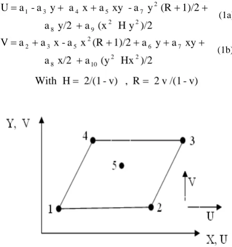
Figure 1 shows the geometric properties of Q4SBE1 element, the corresponding nodal displacements. At each node (i) the degrees of freedom are U i and Vi . The displacement fields of the Q4SBE1 element are given by the following equations (1):
)/2 y H (x a y/2 a 1)/2 (R y a xy a x a y a -a U 2 2 9 8 2 7 5 4 3 1 + + + + + = (1a) )/2 Hx (y a x/2 a xy a y a 1)/2 (R x a x a a V 2 2 10 8 7 6 2 5 3 2 + + + + + + = (1b) v) /(1 v 2 R , v) -2/(1 H
With = =
Fig.1. Coordinates and nodal points for the quadrilateral element” Q4SBE1
Numerical and Experimental Investigation
of an Elliptical Paraboloid Shell Model
C. Rectangular plate element ‘ACM’
The displacement fields of the ACM element (Fig.2) are given by the following equations (2):
xy
a
y
x
a
y
a
xy
a
y
x
a
x
a
y
a
xy
a
x
a
y
a
x
a
a
y)
W(x,
3 12 3 11 3 10 2 9 2 8 3 7 2 6 5 2 4 3 2 1+
+
+
+
+
+
+
+
+
+
+
=
(2 a))
xy
a
3
+
x
a
+
y
a
3
+
xy
2a
+
x
a
+
y
a
2
+
x
a
+
(a
-=
2 12 3 11 2 10 9 2 8 6 5 3 x
θ
(2 b)y
a
+
y
x
a
3
+
y
a
+
xy
2a
+
x
3a
+
y
a
+
x
2a
+
a
=
3 12 2 11 2 9 8 2 7 5 4 2 y
θ
(2c)Fig.2. Coordinates and nodal points for the rectangular plate element
” ACM”
The shell element ACM_Q4SBE1 is composed by assembling the two elements Q4SBE1 and ACM (Fig.3).
Fig.3. The shell element ACM_Q4SBE1
The stiffness matrix of the shellelement ACM_ Q4SBE1 is obtained by using the analytical integration of the membrane and bending stiffness matrix.
The evaluation of the element stiffness matrix is summarized with the evaluation of the following well known expression Eq(3):
[ ]
[ ]
1[ ] [ ][ ]
[ ]
1. . . − − ⎥ ⎦ ⎤ ⎢ ⎣ ⎡
= A
∫∫
Q D Q dxdy AK T
S T
e (3a)
[ ]
[ ]
[ ]
[ ]
10
1 −
−
=
A
K
A
K
e T (3b)With:
[ ]
K
[ ] [ ][ ]
Q
D
.
Q
.
dx
dy
s
T
0
=
∫∫
(3c)III. VALIDATION
The performance of the developed shell element is evaluated on a standard test problems presented in this section.
A. Clamped cylindrical shell
The clamped cylindrical shell presented in Fig.4 (a) is selected as a test problem in literature. The geometrical dimensions, loading and elastic properties are given in Fig.4. Due to symmetry of the cylinder only 1/8 (ABCD) is considered in the finite element idealizations Fig.4 (b).
Fig.4. Clamped cylindrical shell
The results of this analysis are compared to the analytical solution based on the thin shell structures (R/h=100) given by Flugge [9] and Lindberg et al [10] below:
WC = -WC Eh/P = 164, 24 deflection under load P in point
C only.
VD = -VD Eh/P = 4, 11 deflection in Y direction.
TABLE I: CLAMPED CYLINDRICAL SHELL,CONVERGENCE OF WC
Displacement Wc at point C Meshes
ACM_Q4SBE1 ACM-SBQ4 [11] 4 x 4 106,62 101,50 6 x 6 138.30 135,00 8 x 8 156,85 148,226 20 x 4 161,78 157,145
Analytical
solution 164,24
TABLE I I: CLAMPED CYLINDRICAL SHELL,CONVERGENCE OF VD
Displacement Wc at point C Meshes
ACM_Q4SBE1 ACM-SBQ4 [11] 4 x 4 6,206 6.153 6 x 6 4,837 4,809 8 x 8 4,521 4,274 20 x 4 4,179 4,192
Analytical
solution 4,11
The results obtained for both deflections WC and VD for
the refined mesh (20x4) are very good compared to the analytical solution.
B. Scordelis-Lo roof
The next test to be considered which is frequently used to test the performance of shell element is that of Scordelis-Lo roof having the geometry as shown in Fig.5.
Fig.5. Scordelis-Lo roof
The straight edges are free, while the curved edges are supported on rigid diaphragms along their plan. The geometrical and mechanical characteristics are given in Fig.5.
The results obtained by the new formulated element ACM_Q4SBE1 are compared to the reference values based on the deep shell theory. The analytical solution based on the shallow shell theory is given by Scordelis and Lo[12], which is slightly different from the deep shell theory. The results obtained for different meshes are given in Table III
TABLE III: SCORDELIS-LO ROOF ,CONVERGENCE OF WC AND WB
Vertical displacement at point C and B Meshes
WC WB
2 x2 0.7116 - 4.948 4 x 4 0.5582 -3.680 6 x 6 0.5534 -3.674 8 x 8 0.5477 -3.642 9 x 10 0.5475 -3.640
Reference Value 0.541 -3.610
IV. EXPERIMENTAL TEST
Tests on full-scale shells are few because the loading of such structures is difficult and costly. Experimental investigation of shells therefore usually resorts to small-scale tests. Hence, the experimental work described in this study is of this type.
The test model is made of an aluminum alloy in an elliptical shape and has a constant thickness of 2 mm with a plan rectangular projection of 880 mm by 400 mm Fig.6., the material properties have been assumed to be: The modulus of elasticity E = 70000 N/mm2, the Poisson ratio
υ
= 0.33. A uniform normal pressure is applied by covering the shell top surface with a pneumatic pressure bag in close contact with it [13].The model is free along the long edges, fixed at certain points on wooden support along the short edges. Due to the double symmetry in geometry and loading, measuring points are located on one quarter of the area of the model at eight points Fig.7.
Fig.6. The elliptical paraboloid shell undergoing the experimental test
Fig.7. Dial gauge positions; (distance in mm)
V. NUMERICAL AND EXPERIMENTAL RESULTS
The vertical deflections resulting from numerical analysis and experimental work for different loading values are presented in Table IV.
TABLE IV: VERTICAL DISPLACEMENTS W (MM) UNDER DIFFERENT APPLIED LOADINGS
Points 3 4 5 6 7 8
ACM_Q4SBE1 0.24 0.40 2.01 0.16 0.25 0.41 Case a
Load = 25x10−3 N/mm2
Exp.Work 0.19 0.31 1.67 0.13 0.18 0.30 ACM_Q4SBE1 0.48 0.80 4.02 0.32 0.50 0.82 Case b
Load = 50x10−3 N/mm2
Exp.Work 0.49 0.80 3.10 0.33 0.47 0.85 ACM_Q4SBE1 0.72 1.20 6.03 0.48 0.75 1.23 Case c
Load = 75x10−3 N/mm2 Exp.Work 0.66 1.09 5.20 0.43 0.63 1.15
ACM_Q4SBE1 0.96 1.60 8.02 0.65 1.00 1.64 Case d
Load = 100x10−3 N/mm2
VI. CONCLUSION
From the results obtained from the numerical analysis the following conclusion can be drawn:
Fine relatively meshes lead to almost identical results thus proving the efficiency of the strain based element. Excellent agreement is shown between the shell element ACM_Q4SBE1 results and those from experimental work (in inside points).
The presented shell element ‘ACM_Q4SBE1’ has been demonstrated to be robust, effective and useful in analysing thin shell structures.
REFERENCES
[1] B.E. Green, D.R. Strome and R.C Weikel, “Application of the stiffness method to the analysis of shell structures”, Proc. Aviation conference, Amer. Soc. Mech. Eng., Los Angeles, 1961 [2] J. H. Argyris, Matrix displacement analysis of anisotropic shells by
triangular elements, J.Roy. Aer. Soc., Vol. 69, 1965, pp. 801-805. [3] R.W. Clough. and C.P. Johnson, A finite element approximation for
the analysis of thin shells”, J. Solids and Structures, Vol. 4, 1968, pp 43-60.
[4] O.C. Zienkiewicz and R.L. Taylor, "The finite element method in solid and fluid mechanics, dynamics and nonlinearity”, Vol. II, (Mc Graw Hill, New York, 1991).
[5] D. Hamadi, M. Mellas, R. Chebili and M. S. Nouaouria, "An efficient quadrilateral membrane element for civil engineering analysis”, World Journal of Engineering, Vol 4 N°. 1, 2007, pp 54-65.
[6] A. Adini. and R.W. Clough., “Analysis of plate bending by the finite element method”, Report to the Nat. Sci. Found., U.S.A., G 7337, 1961.
[7] R.J. Melosh, “Basis of derivation of matrices for the direct stiffness method”, J.AIAA Vol. 1 N7, 1963, pp. 1631-1637.
[8] D. Hamadi, "Analysis of structures by non-conforming finite elements", PhD Thesis, Civil engineering department, Biskra University, Algeria, 2006, pp. 130.
[9] W. Flugge. and K. Fosberge., “Point load on shallow elliptic paraboloid”, J. Appl. Mech. Vol. 33, 1966, pp. 575-585.
[10] G.M. Lindberg, M.D. Olson. and G.R Cowper., “New development in the finite element analysis of shells”, Q. Bull Div. Mech. Eng. and Nat. Aeronautical Establishment, National Research council of Canada, Vol. 4, 1969.
[11] M.T. Belarbi , “Développement de nouveaux éléments finis basés sur le modèle en déformation. Application linéaire et non linéaire”.
Thèse de Doctorat d’état, Université de Constantine, Algérie, 2000. [12] A.C. Scordelis. and K.S. Lo, “Computer analysis of cylindrical
shells”, J. Amer. Concrete Institute Vol. 61, 1969, pp. 539-561. [13] D. Hamadi, “Numerical and Experimental Investigation of an