8;/575?C .> 35=>? 07.>> 3@90?5;9.75?C, 579<A) 59 ?42 759@B 62=927
1LUFKDRKQPJ <KQQOLMLDUULTDM
. ?KHTLT >VEOLUUHG IQS UKH 1HJSHH QI <K1 DU UKH
@PLWHSTLUZ QI >U .PGSHXT
&$%(
3VNN OHUDGDUD IQS UKLT LUHO LT DWDLNDENH LP =HTHDSFK->U.PGSHXT,3VNN?HYU
DU,
KUUR,##SHTHDSFK!SHRQTLUQSZ"TU!DPGSHXT"DF"VM#
<NHDTH VTH UKLT LGHPULILHS UQ FLUH QS NLPM UQ UKLT LUHO,
KUUR,##KGN"KDPGNH"PHU#%$$&'#*+%(
ILNPv6 in the Linux Kernel
Thesis by
Ditchaphong Phoomikiattisak
In Partial Fulfillment of the Requirements
for the Degree of
Doctor of Philosophy
University of St Andrews
School of Computer Science
Mobility is an increasingly important aspect of communication for the Internet. The usage of
handheld computing devices such as tablets and smartphones is increasingly popular among
Internet users. However, the current Internet protocol, IP, was not originally designed to
support mobility over the Internet. Mobile users currently suffer from connection disruption
when they move around. Once a device changes point of attachments between different
wireless technology (vertical handoff) e.g. from WiFi to 3G, the IP address changes, and the bound session (e.g. TCP session) breaks. While the IETF Mobile IPv4 (MIPv4) and
Mobile IPv6 (MIPv6) solutions have been defined for some time, and implementations are
available, they have seen little deployment due to their complexity and performance.
This thesis has examined how IP mobility can be supported as first class
functional-ity, i.e. mobility can be enabled through the end hosts only, without changing the current
network infrastructure. Current approaches such as MIPv6 require the use of proxies and
tunnels which introduce protocol overhead and impact transport layer performance. The
Identifier-Locator Network Protocol (ILNP) is an alternative approach which potentially
works end-to-end, but this is yet to be tested. This thesis shows that ILNP provides
mobil-ity support as first class functionalmobil-ity, is implemented in an operating system kernel, and is
accessible from the standard API without requiring changes to applications. Mobility
man-agement is controlled and managed by the end-systems, and does not require additional
network-layer entities, only the end hosts need to be upgraded for ILNP to operate. This
work demonstrates an instance of ILNP that is a superset of IPv6, called ILNPv6, that is
implemented by extending the current IPv6 code in the Linux kernel. A direct performance
comparison of ILNPv6 and MIPv6 is presented, showing the improved control and
perfor-mance of ILNPv6, in terms of flow continuity, packet loss, handoff delay, and signalling
overhead.
I, Ditchaphong Phoomikiattisak, certify that this thesis, which is approximately
37,000 words in length, has been written by me, that it is the record of work carried
out by me and that it has not been submitted in any previous application for a higher
degree.
Date . . . Signature of candidate . . . .
I was admitted as a research student in September 2012 and as a candidate for the
degree of Doctor of Philosophy in September, 2015; the higher study for which this
is a record was carried out in the University of St Andrews between 2012 and 2015.
Date . . . Signature of candidate . . . .
I hereby certify that the candidate has fulfilled the conditions of the Resolution and
Regulations appropriate for the degree of Doctor of Philosophy in the University of
St Andrews and that the candidate is qualified to submit this thesis in application
for that degree.
Date . . . Signature of supervisor . . . .
In submitting this thesis to the University of St Andrews I understand that I am
giv-ing permission for it to be made available for use in accordance with the regulations of
the University Library for the time being in force, subject to any copyright vested in
the work not being affected thereby. I also understand that the title and abstract will be published, and that a copy of the work may be made and supplied to anybona fide
library or research worker, that my thesis will be electronically accessible for personal
or research use unless exempt by award of an embargo as requested below, and that
the library has the right to migrate my thesis into new electronic forms as required
to ensure continued access to the thesis. I have obtained any third-party copyright
permissions that may be required in order to allow such access and migration, or have
requested the appropriate embargo below.
The following is an agreed request by candidate and supervisor regarding the
elec-tronic publication of this thesis:
Access to printed copy and electronic publication of thesis through the University
of St Andrews.
Date . . . Signature of candidate . . . .
Date . . . Signature of supervisor . . . .
To Prof. Saleem Bhatti, my supervisor, for your wisdom, guidance and support of
everything.
To my parents, for your love, care, support, and many other things which cannot be
explained here.
To Simon Dobson, my second supervisor, for all kind suggestions.
To Tristan Henderson, for your ‘straightforward’ reviews and comments that help lift
up the standard of my work.
To Chusin Mateechaipong, my best friend, who always be there when I need.
To Chonlatee Khorakhun, Yuchen Zhao, Luke Hutton, Khawar Shehzad, my (ex)offi ce-mates, for sharing ideas, happiness and time together.
To Bruce Simpson, for sharing tons of useful stuff for my research.
To the school system team and administration team, for your assistance in every tiny
single matter.
Some of the work presented in this thesis has been published.
D. Phoomikiattisak, S. N. Bhatti. Mobility as a First Class Function. Proceedings
ofthe 11th IEEE International Conference on Wireless and Mobile Computing,
Net-working and Communications (WiMob2015). Abu Dhabi, UAE. Oct 2015.
S. N. Bhatti, D. Phoomikiattisak, R. J. Atkinson. Fast, Secure Failover for IP.
Pro-ceedings of the 33rd IEEE Military Communications Conference (MILCOM 2014).
Baltimore, MD, USA. Oct 2014.
D. Phoomikiattisak, S. N. Bhatti. IP-Layer Soft Handoff Implementation in ILNP. Proceedings of the 9th ACM Workshop on Mobility in the Evolving Internet
Archi-tecture (MobiArch2014). Maui, Hawaii, USA. Sep 2014.
D. Phoomikiattisak, S. N. Bhatti. Network Layer Soft Handoff for IP Mobility. Pro-ceedings of the 8th ACM workshop on Performance Monitoring and Measurement of
Heterogeneous Wireless and Wired Networks (PM2HW2N2013). Barcelona, Spain.
Nov 2013.
AD– Administrative Domian
AH– Authentication Header
API– Application Program Interface
BAck– Binding Acknowledgement
BTMM– Back to My Mac
BU– Binding Update
CAPEX– Capital Expenditure
CGA– Cryptographically Generated Addresses
CN – Correspondent Node
CoA– Care-of-Address
CoT– Care-of Test
CoTI – Care-of Test Init
DAD– Duplicate Address Detection
DHCP– Dynamic Host Configuration Protocol
DCCP – Datagram Congestion Control Protocol
DMM– Distributed Mobility Management
DNS – Domain Name System
E2E– End-to-End
EID – Endpoint Identifier
ESD– End System Designator
ESP – Encapsulating Security Payload
ETR – Egress Tunnel Router
EUI-64 – 64-bit Extended Unique Identifier
FA– Foreign Agent
xii GLOSSARY
FMIPv6– Fast Handover for Mobile IPv6
FN – Foreign Network
FQDN – Fully Qualified Domain Name
GL– Global Locator
GLI-Split– Global Locator, Local Locator, and Identifier Split
GSE – Global, Site, and End-system address elements
GSO – Generic Segmentation Offload
HA– Home Agent
HAHA– Home Agent to Home Agent
HAWAII – Handoff-Aware Wireless Access Internet Infrastructure
HI – Host Identifier
HIP– Host Identity Protocol
HMIPv6– Hierarchical Mobile IPv6
HN– Home Network
HoA – Home Address
HoT– Home Test
HoTI – Home Test Init
IAB – Internet Architecture Board
ICMP– Internet Control Message Protocol
ID– Identifier
IEEE – Institute of Electrical and Electronics Engineers
IEN– Internet Experiment Note
IETF – Internet Engineering Task Force
IKE– Internet Key Exchange
ILCC– ILNP Communication Cache
ILNP – Identifier Locator Network Protocol
IL-V– Identifier Locator Vector
IoT– Internet of Things
IP – Internet Protocol
IPv4– IP version 4
IPSec– Internet Protocol Security
IRTF– Internet Research Task Force
ISP – Internet Service Provider
ITR– Ingress Tunnel Router
L – Locator
L64 – 64-bit Locator
LCoA– Local Care-of-Address
LISP– Locator/Identifier Separation Protocol
LL – Local Locator
LMA – Local Mobility Anchor
LSR – Loose Source Routing
LTE– Long-Term Evolution
LU– Locator Update
LU-ACK – Locator Update Acknowledgement
MAC – Media Access Control
MAG– Mobile Access Gateway
MAN – Metropolitan Area Network
MAP – Mobility Anchor Point
MAS– Mobile Access Station
MILSA– Mobility and Multihoming Supporting Identifier Locator Split Architecture
MIP – Mobile IP
MIPv4 – Mobile IP version 4
MIPv6 – Mobile IP version 6
MN– Mobile Node
MOBIKE – IKEv2 Mobility and Multihoming Protocol
MP-TCP– Multipath TCP
MR – Mobile Router
M-SCTP – Mobile Stream Control Transmission Protocol
MSM-IP – Mobility Support Using Multicast in IP
MSS– Maximum Segment Size
xiv GLOSSARY
NAR– New Access Router
ND – Neighbour Discovery
NAT – Network Address Translation
NEMO – Network Mobility
NID– Node Identifier
NR– Node Identity Router
OPEX – Operational Expenditure
OS – Operating System
PAR – Previous Access Router
PMIPv6– Proxy Mobile IPv6
QoE – Quality of Experience
QoS – Quality of Service
RA – Router Advertisement
RANGI – Routing Architecture for the Next Generation Internet
RCoA – Regional Care-of-Address
RG – Routing Goop
RFC– Request for Comments
RLOC– Routing Locator
RM – Realm Manager
RO– Route Optimisation
RVS – Rendezvous Server
RTT – Round-trip Time
SA – Security Association
SBR– Site Border Router
SCTP– Session Initiation Protocol
SHIM6– Level 3 Multihoming Shim Protocol for IPv6
SIP– Stream Control Transmission Protocol
SLAAC– Stateless Address Autoconfiguration
TCP – Transmission Control Protocol
TMIP – Terminal Independent Mobile IP
TTL – Time-to-Live
UDP– User Datagram Protocol
ULID– Upper Layer Identifier
VIP– Virtual Internet Protocol
VoIP– Voice over IP
VNA – Virtual Network Address
WAN– Wide Area Network
WLAN– Wireless Local Area Network
RFC document types
BCP– Best Current PracticeDS– Draft Standard
E – Experimental
I – Informational
Abstract i
Declaration iii
Copyright v
Acknowledgements vii
Published Research ix
Glossary xi
List of Figures xxi
List of Tables xxix
Chapter 1. Introduction 1
1.1. Host Mobility 1
1.2. Importance of Network Layer Solutions to Host Mobility 2
1.3. Host Mobility and Network Mobility 4
1.4. Challenges in Host Mobility Support 4
1.4.1. Challenges in Architecture 4
1.4.2. Challenges in Engineering 5
1.5. Thesis Outline 6
1.6. Thesis Structure 7
Chapter 2. History of IP Mobility 9
2.1. Issues in Use of IP Addresses for Mobility 9
2.2. Addressing, Location and Identity 11
2.3. IEN 135 – A Very First Host Mobility Solution 12
xviii CONTENTS
2.4. Current Host Mobility Solutions 13
2.4.1. Network-based Mobility Solutions 15
2.4.2. Host-based Mobility Solution 19
2.4.3. Transport Layer Solutions 21
2.4.4. Other Approaches for Host Mobility 23
2.5. Mobile IP 25
2.6. Identifier Locator Network Protocol (ILNP) 27
2.6.1. ILNP Architectural Concepts 28
2.6.2. ILNPv6 – An Engineering of ILNP 29
2.6.3. Host Mobility with ILNP 29
2.6.4. Security Considerations 32
2.6.5. Interoperation with Other Features 34
2.6.6. An Alternative ILNPv6 Prototype 36
2.7. Summary 38
Chapter 3. Changing the IP Layer in the Linux Kernel 39
3.1. Feasibility Study of Host Mobility Using ILNP 39
3.1.1. Experiment Configuration 40
3.1.2. Results 42
3.2. ILNPv6 Detailed Design and Implementation in Linux 44
3.2.1. Encoding NID and L64 values 45
3.2.2. Name Resolution 45
3.2.3. Identifying ILNPv6 Sockets 46
3.2.4. ILNP Communication Cache (ILCC) 46
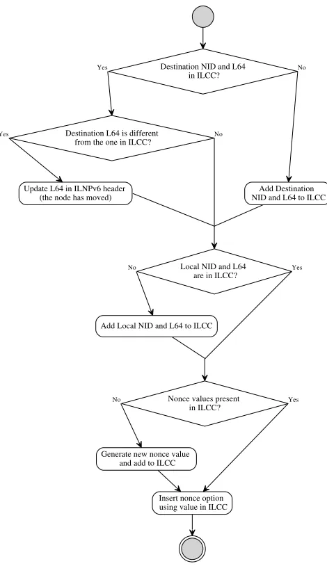
3.2.5. Sending ILNPv6 Packets 47
3.2.6. Receiving ILNPv6 Packets 48
3.2.7. Handoff Management 49
3.2.8. Extensions to Transport Layer Protocols 54
3.3. Initial Evaluation 55
3.3.1. Experiment Configuration 56
3.3.2. Results 58
3.4.1. Experiment Design and Limitations 63
3.5. Summary 63
Chapter 4. UDP Operation and Performance over ILNPv6 65
4.1. Extension to the Linux Kernel for UDP Operation 66
4.2. Rationale for the Evaluation 67
4.3. Experiment Configuration 68
4.4. Results 70
4.4.1. Handoff Performance 70
4.4.2. Analysis of Overall Flow 73
4.5. Summary 83
Chapter 5. TCP Operation and Performance over ILNPv6 85
5.1. Extension to the Linux Kernel for TCP Operation 85
5.1.1. Limitations 88
5.2. Experiment Configuration 88
5.3. Results 89
5.3.1. TCP Flow Data Rate Behaviour 90
5.3.2. Successfully Transferred Data 95
5.3.3. Retransmission Attempted 98
5.3.4. Packet Loss 100
5.3.5. Handoff Delay 101
5.4. Discussion and Future Works 103
5.5. Summary 104
Chapter 6. Control Plane Analyses 105
6.1. Overview of Signalling Used 105
6.2. Impacts of Lossy Environment 107
6.2.1. Handoff Success Rate Calculation 108
6.2.2. Loss Scenarios 111
6.2.3. Results 111
6.3. Impacts of Signalling Packets Loss 113
xx CONTENTS
6.3.2. With Signalling Packet Loss 115
6.3.3. Results 122
6.4. Scalability 125
6.4.1. Overhead Calculation 125
6.4.2. Results 128
6.4.3. Discussion 130
6.5. Summary 131
Chapter 7. Conclusion and Future Works 133
7.1. Conclusion 133
7.2. Discussion 135
7.2.1. Name Resolution Using DNS 135
7.2.2. Simultaneous Mobility 136
7.2.3. Applicablility to Vertical Handoff 137
7.2.4. Managing changes in QoS on Handoff 138
7.2.5. Backwards Compatibility with IPv6 138
7.2.6. Security Considerations 139
7.2.7. Privacy Considerations 140
7.2.8. Energy Usage 141
7.3. Future Works 141
1.1 An example of handoff scenario. When a mobile node (MN) handoff under the same underlying technology, for example WiFi, it does a horizontal
handoff. However, when it moves across wireless technology, for example
WiFi to 3G, it performs a vertical handoff. 2
2.1 An example scenario of host mobility with MIPv6. 26
2.2 IPv6 unicast address format and ILNPv6 unicast address format. The L64
value has the same syntax and semantics as the IPv6 routing prefix. The
NID value has the same syntax as the IPv6 Interface Identifier, but has
different semantics. 30
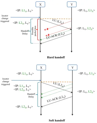
2.3 An example scenario of host mobility with ILNP (with soft handoff). 32
2.4 A Comparison of Hard Handoff and Soft Handoff Using ILNP. 33
2.5 An example scenario of network mobility with ILNP using the “Locator
Rewriting” mechanism. 36
3.1 The topology for the overlay experiment. The hosts H1 and H2 reside in
different networks, with Locator values of L1 and L2, respectively. The green / dashed arrows identify movements of H2 between site networks
using L64 values L2 and L3, generating a handoff. 41
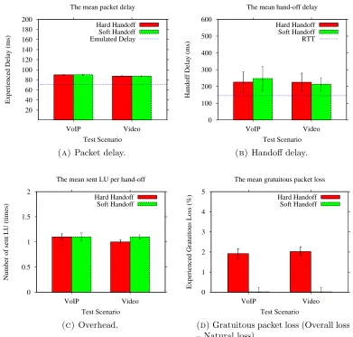
3.2 The mean packet loss. Error bars at 95% confidence. 42
3.3 The mean packet delay. Error bars at 95% confidence. 43
3.4 The mean handoff delay. Error bars at 95% confidence. 43
3.5 The mean sent LU per handoff. Error bars at 95% confidence. 44
xxii LIST OF FIGURES
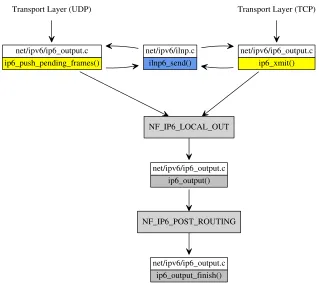
3.6 A function call graph in the Linux kernel for sending a packet in network
layer . The grey boxes are unmodified functions. The functions in yellow
boxes are modified, and a new function is shown in blue. 48
3.7 A flowchart of ilnp send() function. 49
3.8 A function call graph in the Linux kernel for receiving a packet in network
layer. The grey boxes are unmodified functions. The functions in yellow
boxes are modified, and a new functions are shown in blue. 50
3.9 A flowchart of ilnp rcv() function. 51
3.10 A function call graph of handling RA in the Linux kernel. The grey boxes
are unmodified functions. The functions in yellow boxes are modified, and
a new functions are shown in a blue. 52
3.11 A function call graph of handling LU in the Linux kernel. The functions in
yellow boxes are modified, and a new functions are shown in a blue. 52
3.12 Implementation of changes of L64 status during hard handoff and soft
handoff. 53
3.13 The topology for the initial experiment. The hosts H1 and H2 reside in
different networks, with Locator values of L1 and L2, respectively. The green / dashed arrows identify movements of H2 between site networks
generating a handoff. 56
3.14 The cumulative frequency distribution of one-way delay of WiFi network
(St Andrews) and 3G network (a UK provider). 57
3.15 Performance of hard and soft handoff. Error bars at 95% confidence from 10 runs. Horizontal/bue lines are ‘natural’ values. 59
3.16 The diagram of the testbed for performance evaluation of UDP and TCP
over ILNPv6 and MIPv6. The green boxes are machines connected by
wired Ethernet 1Gbps, as shown in black lines. The blue radio antennas
represent 802.11ac 2x2 WLAN links. 61
3.18 The wireless dual-band USB adapter (Edimax EW-7822UAC) used to
provide wireless conectivity for the testbed1
62
4.1 A function call graph in the Linux kernel for sending a packet in UDP
layer. The grey boxes are unmodified functions, and the functions in yellow
boxes are modified. 66
4.2 A function call graph in the Linux kernel for receiving a packet in UDP
layer. The grey boxes are unmodified functions, and the functions in yellow
boxes are modified. 67
4.3 The topology for the experiment. The CN connects to R1 via 1Gbps
ethernet. The MN initially connects to R2(HA) using WLAN – the dashed
/ blue circles depict the radio cell scenario being emulated. The green /
dashed arrows identify movements of MN to site network L3 generating a
handoff. 69
4.4 Throughput for a 5 second period across the handoff period for the UDP emulated traffic flows. Error bars at 95% confidence. 71
4.5 Packet loss for a 5 second period across the handoff period for the UDP emulated traffic flows. Error bars at 95% confidence. ILNP soft handoff has zeroloss hence it does not visible in the bar charts. 72
4.6 Handoff delay for the HD Video emulated traffic flows. ILNP handoff was
∼1 RTT. 73
4.7 Handoff delay for the VoIP emulated traffic flows. ILNP handoff was ∼1
RTT. 74
4.8 Communication flow for the UDP emulated HD Video traffic flows showing the data rate (bytes/sec) at the MN, LAN to LAN handoff. There was an interruption during the MN handoff for MIPv6, but no interruption for
ILNPv6. 75
xxiv LIST OF FIGURES
4.10 Communication flow for the UDP emulated HD Video traffic flows showing the data rate (bytes/sec) at the MN, LAN to WAN handoff. There was an interruption during the MN handoff for MIPv6, and a small drop of throughput for ILNPv6 hard handoff and soft handoff. 77
4.11 Sequence number graph for the HD Video emulated traffic flows, LAN to WAN handoff. There was a gap of sequence number (implying packet loss) during the MN handoff for MIPv6 and ILNPv6 hard handoff. For ILNPv6 soft handoff, there is a small delay before the sequence number continues. 78
4.12 Communication flow for the UDP emulated HD Video traffic flows showing the data rate (bytes/sec) at the MN, WAN to LAN handoff. There was an interruption during the MN handoff for MIPv6, while no interruption for ILNPv6. There was a peak of throughput after handoff for MIPv6 with
RO and ILNPv6 soft handoff. 79
4.13 Sequence number graph for the HD Video emulated traffic flows, WAN to LAN handoff. There was a gap of sequence number (implying packet loss) during the MN handoff for MIPv6. A small rise of sequence number after handoff is found when RO was enabled. There is a small jump in sequence number (indicating packet loss) for ILNPv6 hard handoff. For ILNPv6 soft handoff, there is an overlap of sequence number showing multipath delivery
via multihoming during handoff. 80
4.14 Communication flow for the UDP emulated HD Video traffic flows showing the data rate (bytes/sec) at the MN, WAN to WAN handoff. There was an interruption during the MN handoff for MIPv6, a drop of data rate for ILNPv6 hard handoff, and no interruption for ILNPv6 soft handoff. 81
4.15 Sequence number graph for the HD Video emulated traffic flows, WAN to WAN handoff. There was a gap of sequence number (implying packet loss) during the MN handoff for MIPv6 and ILNPv6 hard handoff. A small rise of sequence number was found when RO was enabled. For ILNPv6 soft
5.1 A function call graph in the Linux kernel for sending a packet in TCP
layer. The grey boxes are unmodified functions, and the functions in yellow
are modified. 86
5.2 A function call graph in the Linux kernel for receiving a packet in TCP
layer. The grey boxes are unmodified functions, and the functions in yellow
are modified. 87
5.3 The topology for the experiment. The CN connects to R1 via 1Gbps
ethernet. The MN initially connects to R2(HA) using WLAN – the dashed
/ blue circles depict the radio cell scenario being emulated. The green /
dashed arrows identify movements of MN to site network L3 generating a
handoff. 89
5.4 Communication flow for the TCP traffic showing the data rate (bytes/sec) at the MN, LAN to LAN handoff. There was an interruption during the MN handoff for MIPv6, while there was a small drop in data rate for
ILNPv6. 92
5.5 Communication flow for the TCP traffic showing the data rate (bytes/sec) at the MN, LAN to WAN handoff. There was an interruption during the MN handoff for MIPv6 and ILNPv6 hard handoff, while there was no interruption for ILNPv6 soft handoff. The data rate dropped after the
handoff due to higher delay. 93
5.6 Communication flow for the TCP traffic showing the data rate (bytes/sec) at the MN, WAN to LAN handoff. There was an interruption during the MN handoff for MIPv6, while there was no interruption for ILNPv6. The data rate increased after the handoff due to a lower delay link, except
MIPv6 without RO, where the traffic still traversed the high delay link. 94
5.7 Communication flow for the TCP traffic showing the data rate (bytes/sec) at the MN, WAN to WAN handoff. There was an interruption during the MN handoff for MIPv6 and ILNPv6 hard handoff, while there was no
xxvi LIST OF FIGURES
5.8 Total data transfer volumes during 30 second TCP traffic flows. Error bars at 95% confidence. With ILNPv6, TCP can transfer more data than
with MIPv6 in almost every case, except when handoff from LAN to WAN because the MN stays in the LAN link longer when MIPv6 is in used. 97
5.9 Number of retransmission attempted at the CN. ILNP with soft handoff
had the lowest number of retransmissions. 98
5.10 Number of lost packets in each flow. ILNP with soft handoff has the lowest number of packet loss, and is near to zero. 101
5.11 Handoff delay for TCP traffic flows. ILNP handoff was ∼1 RTT. 102
6.1 Control signals used during an MN handoff using MIPv6 without RO. 105
6.2 Control signals used during an MN handoff using MIPv6 with RO. 106
6.3 Control signals used during an MN handoff using ILNPv6. 106
6.4 Topology for signalling analysis. Combinations of packet loss rates are
introduced at (1) and (2). 108
6.5 Control signal paths during an MN handoff. 110
6.6 Signalling packets used in MIPv6 without RO in the case that a BU is lost 116
6.7 Signalling packets used in MIPv6 without RO in the case that a BAck is
lost 116
6.8 Signalling packets used in MIPv6 with RO in the case that a BU is lost 117
6.9 Signalling packets used in MIPv6 with RO in the case that a BAck is lost 118
6.10 Signalling packets used in MIPv6 with RO, in the case that one of RO
packets is lost. 119
6.11 Signalling packets used in ILNPv6 in the case that an LU is lost 120
6.12 Signalling packets used in ILNPv6 in the case that an LU-ACK is lost 120
6.13 Overhead packets. ILNPv6 has a much lower number of overhead packets
compared to MIPv6 with RO. MIPv6 without RO yeilds the smallest
6.14 Overhead bytes. ILNPv6 has a much lower number of overhead in bytes
compared to MIPv6 with RO. MIPv6 without RO yeilds the smallest byte
overhead, and increases only when the number of MNs increases. 129
2.1 Use of names in IP. 10
2.2 Comparison of Mobility Management Solutions 14
2.3 Use of names in IP and ILNP (extended version of Table 2.1). 29
2.4 Comparison of the alternative prototype and the prototype in this thesis. 37
3.1 Overlay protocol stack of the prototype. 40
3.2 Important members of an ILCC entry. 47
3.3 Important members of struct l64 info. 47
3.4 Status of L64 values in the ILCC [13]. 51
3.5 Network characteristics of WiFi and 3G. 56
3.6 Summary of the testbed hardware and software. 60
6.1 Individual probabilities under different packet loss rates. 112
6.2 Probability of handoff success rate, under different loss conditions 113
6.3 Summary of expressions for handoff Delay 121
6.4 Summary of expressions for interruption time 121
6.5 Handoff Delay (ms) LAN to LAN handoff scenario 123
6.6 Interruption time (ms) LAN to LAN handoff scenario 123
6.7 Handoff Delay (ms) for LAN to WAN handoff scenario 123
6.8 Interruption time (ms) for LAN to WAN handoff scenario 123
6.9 Handoff Delay (ms) for WAN to LAN handoff scenario 124
6.10 Interruption time (ms) for WAN to LAN handoff scenario 124
6.11 Handoff Delay (ms) for WAN to WAN handoff scenario 124
xxx LIST OF TABLES
Introduction
The use of portable devices, including laptops, smartphones and tablets has been
increasingly popular1
. Moreover, a new range of products, such as Google glass,
smart watches and other wearable devices have increasingly appeared, and might be
widely used in the near future. Those devices usually prefer to stay connected to
the network continuously. However, there is still no single wireless technology that
provides full coverage with satisfactory quality of service (QoS). Hence, changes of
point of network attachment between different wireless technologies when the users move is inevitable. Nevertheless, the current Internet architecture does not provide
sufficient support for mobile devices. The widely used Internet Protocol, IP, was not designed for hosts that require frequent changes in point of attachment. Therefore,
developing new architecture to enable host mobility support is highly desirable.
In this thesis, the term mobile node (MN), defined as “An IP node capable of
changing its point of attachment to the network.” [70], will be used for representing
portable/mobile devices in general.
1.1. Host Mobility
According to RFC3753 (I) [70], the termhost mobility supportrefers to the “function
of allowing a mobile node to change its point of attachment to the network, without
interrupting IP packet delivery to/from that node.” The term handover or handoff
1
http://www.smartinsights.com/mobile-marketing/mobile-marketing-analytics/
mobile-marketing-statistics/
2 1. INTRODUCTION
(the latter will be used throughout this thesis) is used to describe the action when
an MN changes, or attempts to change, its point of attachment to the network.
Generally, there are two types of handoff: horizontal handoff and vertical handoff. Horizontal handoff considers a scenario when an MN moves between access points of the same wireless type, such as from WiFi to WiFi. However, if the mobile node moves
between access points of different wireless type, such as WiFi to 3G, the movement is considered as a vertical handoff. Also, a movement across administrative domains that results in a change of network layer topology is considered as a vertical handoff. An example scenario of horizontal handoffand vertical handoff is shown in Figure 1.1
3G WiFi
(AP2) WiFi
(AP1)
!"# !"# Vertical handoff !"# Horizontal
handoff
Figure 1.1. An example of handoff scenario. When a mobile node
(MN) handoffunder the same underlying technology, for example WiFi, it does a horizontal handoff. However, when it moves across wireless technology, for example WiFi to 3G, it performs a vertical handoff.
1.2. Importance of Network Layer Solutions to Host Mobility
As the use of mobile devices and methods of wireless connectivity continue to increase,
seamless mobility becomes more desirable and important. Seamless mobility here
means that a device with packet flows in progress can continue its flows even if
there are changes to: (a) its physical connectivity (e.g. it moves from 3G to WiFi);
or (b) its network layer (domain) connectivity (e.g. it changes from IP network
A to IP network B, which might also occur when changing physical connectivity).
While mobility using the same underlying technology –horizontal handoff(e.g. WiFi
communication sessions at the lower layers (e.g. the work by IEEE 802.21 Working
Group2
), the ‘natural’ place for such interworking across technologies is the network
layer.
There are also potential solutions at the transport layer and the application layer.
However, they usually have limitations and might not support mobility for every
type of service. Transport layer solutions like Stream Control Transmission Protocol
(SCTP) [110] and Multipath TCP (MP-TCP) [46, 47] provide mobility support for
only specific transport protocols, which means they do not support applications that
use different protocols such as UDP. Application layer solutions like Session Initia-tion Protocol (SIP)[101] provide mobility support by integrating infrastructure with
some services, e.g. VoIP. However, not all types of services and applications can be
supported by SIP. Therefore, the network layer is the most suitable place to tackle
the host mobility issue for IP based applications.
The use of vertical handoff holds many significant challenges. The key issue is managing the change in network-layer connectivity. Typically, different physical con-nectivity, e.g. changes in network interface, also involve changes to network-layer
connectivity – changes in the topological connectivity (location) of a device.
Seamlessvertical handoffis highly desired because, currently (at the time of
writ-ing this thesis), there is still no swrit-ingle wireless technology, neither WiFi, 3G, LTE,
nor others, that provide a full and ubiquitous coverage. Therefore, a combination of
those technologies, and switching among them (i.e. vertical handoff), are indispens-able. Hence, an effective network layer solution is required.
Seamless host mobility also could be a basis for various future functionalities. For
example, it is one of the keys to enable Ubiquitous Computing or The Internet of
Things (IoT), when everything is always connected and communicating, as Weiser
stated that“sufficient infrastructure for highly mobile devices” is required [118].
2
4 1. INTRODUCTION
1.3. Host Mobility and Network Mobility
Apart from host mobility, there is also another type of mobility, called network
mo-bility or site mobility, where an entire network, instead of just a node, changes its
point of attachment. Support of network mobility is usually based on support of host
mobility. For example, the IETF NEMO [39] is an extension to Mobile IPv6. For
ILNP, network mobility support is possible, essentially, based on the same
mecha-nism that enables host mobility. However, this work focusses on only host mobility;
investigation of network mobility isnotincluded this thesis, and would be a separate
and distinct body of research.
1.4. Challenges in Host Mobility Support
1.4.1. Challenges in Architecture.
(a). Addressing.
The key challenge to enable host mobility support is how to address an MN. The
current IP address scheme has been identified as not suitable for MNs [22, 31, 74, 102]
– see details in Section 2.1. The proposed mobility solutions use different mecha-nisms to handle the addressing problem. For example, Mobile IP uses two different IP addresses, Host Identity Protocol (HIP) uses public/private key scheme with an
IP address, and Identifier Locator Network Protocol (ILNP) uses encoded identifier
and locator values in an IPv6 address field. However, each has its advantages and
disadvantages.
(b). Network-based and host-based mobility management.
Solutions to host mobility can be divided to host-based and network-based
mecha-nisms, depending on whether the mobility management is done by the end hosts, or
by additional network entities. Chapter 2 will provide more details of advantages and
disadvantages of those two types of mobility management solutions. This thesis takes
1.4.2. Challenges in Engineering.
(a). Difficulty in implementation.
Both host-based and network-based solutions have their own difficulty in implemen-tation. Network-based solution requires new modules or new equipment in the core
network, while host-based solutions need updates to the end-system protocol stack,
which means modifying the operating system’s kernel.
(b). Backward compatibility.
Since the current Internet architecture is quite mature, ideally, mobility support
so-lutions should be backward compatible with the current infrastructure – no changes
required for the current Internet landscape. Also, it is beneficial if the current
appli-cations need not to be modified to operate over a new architecture. Of course, some
additional mechanisms may be required for interoperating between mobility-aware
nodes and non-mobility-aware nodes.
(c). Handoff performance.
Many mobility management mechanisms have been proposed during the last few
decades. However, none of them are widely adopted, partly due to a poor
hand-off performance. Most solutions use a hard handoff model or the break-before-make
mechanism: the ‘old’ network connectivity is dropped before the ‘new’ network
con-nectivity is initiated. Hence, there may be packets ‘in flight’ when handoff occurs, and so gratuitous packet loss occurs. Ideally, the soft handoff model or the
make-before-break mechanism should be used: the ‘new’ connection is created before the
‘old’ one is disconnected. So, the MN can receive data from both old and new links
during handoff, and gratuitous packet loss is minimised. (d). Quality of Service (QoS).
A vertical handoff causes a difficulty in managing QoS of the ongoing communication session. An MN could move between networks with different QoS, e.g. different bandwidth, delay, loss and bit error rate. Therefore, even though a soft handoff solution could minimise gratuitous packet loss during handoff, the application could still have a problem of quality of experience (QoE), for instance, if the MN handoff is from a high speed link to a lower bandwidth, and higher delay link. So, the
6 1. INTRODUCTION
previous works attempting to improve the QoE of the applications for Mobile IP [67],
and for mobile network environments [76]. However, this is an application level issue
and is not addressed in this thesis.
1.5. Thesis Outline
Thesis Statement: IP layer mobility can be supported as ‘first class functionality’
by using end hosts only, without changing current network infrastructure
At the moment, mobility support over multiple networks in the IP layer (network
layer) is enabled by introducing additional entities, i.e. Home Agent and Foreign
Agent in Mobile IP, which are supplementary to the network infrastructure. This is
not only difficult to deploy, but also has problems in working with existing systems and protocols such as IPSec [61], Network Address Translation (NAT) [109] and
Firewall. Identifier Locator Network Protocol (ILNP) [7–16, 18] has good potential
to provide IP mobility asfirst class functionality with satisfying performance. Here,
first class functionalitymeans that mobility management is not supplementary to the
architecture: it is controlled and managed by the end-systems, and can work with
existing APIs and applications. ILNP could address the challenges mentioned above,
as follows.
• Addressing – ILNP uses the concept of identifier/locator split to handle
changes in point of attachment of a MN.
• Mobility management – ILNP is a host-based architecture, so no additional
entities required to the network infrastructure, hosts signal each other
di-rectly.
• Backward compatibility – ILNP is backward compatible with the current
IPv6 infrastructure, does not require changes to the current socket API
(which means legacy applications can operate without changes), and has
• Handoff performance – ILNP could use the soft handoff model, which min-imises gratuitous packet loss during handoff. Nevertheless, the handoff per-formace in a real network environment would still need to be evaluated.
Although ILNP has a strong architectural concept, the engineering design for an
operating system (OS) is not defined. There is no evidence that it can provide host
mobility support in the real network, end-to-end, as part of a real OS. A
compre-hensive evaluation of any ILNP implementation has not been presented. This work
aims to investigate performance of host mobility using ILNP in a real network, not
an overlay network, simulation or emulation. The following are 3 research questions
of this work to fill the gap between architectural concept and engineering.
(1) Implementation: How can ILNP mobility actually be built as an end-to-end
functionality as part of an end-system’s network stack? To be answered in
Chapter 3 of the thesis.
(2) Performance: How good is the performance that ILNP can provide for
mo-bility support from an application point of view, compared to MIPv6? To
be answered in Chapter 4 and 5 of the thesis.
(3) Handoff Signalling: How does ILNP handoff signalling affect the network, compared to MIPv6? To be answered in Chapter 6 of the thesis.
1.6. Thesis Structure
Chapter 1 introduces the concept, importance and challenges of host mobility. The
thesis outline and structure are also presented here.
Chapter 2 surveys the past and present state of host mobility support. The chapter
starts with the problems of using the IP address in a host mobility environment.
Then, a selection of current standardised mobility solutions are overviewed. Finally,
descriptive reviews of MIPv6 and ILNP are presented – both are selected for in-depth
8 1. INTRODUCTION
Chapter 3 shows how ILNPv6 could be implemented in the Linux kernel, using a
dual stack approach. The chapter begins with a feasibility study using an overlay
network to show that host mobility using ILNPv6 is possible. The rest of the chapter
demonstrates how IPv6 in the Linux kernel could be enhanced to enable ILNPv6
functionalities.
Chapter 4 presents a performance comparison of the implemented ILNPv6 and MIPv6
using a UDP application. The purpose of this chapter is to show that handoff per-formance of ILNPv6 is better than MIPv6. This is evidence that ILNPv6 is able to
provide mobility support over a real network. The chapter also explains how UDP in
the Linux kernel could be extended to support ILNPv6.
Chapter 5 studies performance of TCP over ILNPv6 and MIPv6. This is to investigate
how a handoff, by ILNPv6 and MIPv6, impacts TCP behaviour. Again, the evalu-ation here demonstrates that ILNPv6 is able to provide mobility support to TCP
applications over a real network, with better performance than MIPv6. However,
there may be some fine tuning required to TCP in order to optimise its performance
when operating with ILNPv6.
Chapter 6 analyses the handoff signalling used in MIPv6 and ILNPv6. There are three analyses, which aim to verify: i) how does a lossy network impact handoff sig-nals and handoffsuccess rate; ii) what would happen if a signalling packet is lost; and iii) how much extra overhead do ILNPv6 and MIPv6 generate in the network when
providing mobility for a high number of MNs. The study here shows that ILNPv6
handoff signalling is more efficient than MIPv6.
Chapter 7 summarises how the work has fulfilled the research questions towards host
mobility mentioned earlier. There are also discussions of future work regarding
History of IP Mobility
This chapter surveys the history of IP mobility solutions from past to present. First,
the problems of using IP address for MNs are described. Then a selection of mobility
solutions is reviewed, and a comparison to ILNP is made where necessary.
2.1. Issues in Use of IP Addresses for Mobility
The reason that a special mechanism is required for host mobility support is that the
use of IP addresses alone is insufficient. In fact, not only for host mobility, use of IP addresses also has problems with other IP functions such as multihoming, failover,
concurrent sessions via multiple interfaces, and roaming, as Carpenter discusses [32].
Those problems share the same root cause: semantic overloading of the IP address,
where a dynamic change of IP address affects the on-going communication session. The fundamental problem for host mobility using IP can be explained by
consider-ing the bindconsider-ings of an IP address within the protocol stack, as shown in Table 2.1 [12].
The second column of Table 1 shows that the IP address is used in state information
for the transport layer, and it is also assigned to a specific physical interface: the IP
address acts as an identifier at both the transport and physical layer. Effectively, a transport layer communication session is bound 1:1 to a physical interface. Also, if
an application flow uses the IP address instead of a Fully Qualified Domain Name
(FQDN) for its session state, then that application-layer session is also bound to a
specific physical interface. Meanwhile, the IP address is used for routing at the
net-work layer: the IP address acts as a topologicallocator. Hence, when an MN performs
10 2. HISTORY OF IP MOBILITY
a handoff between different networks (e.g. switching from a WiFi interface to a 3G interface), it should, using this model, changes IP addresses, and the change of IP
addresses results in the transport session state, and perhaps the application session
state, becoming invalid.
Table 2.1. Use of names in IP.
Protocol layer IPv4 and IPv6 Application FQDN*, IP address Transport IP address
Network IP address
(interface) IP address
* FQDN: Fully Qualified Domain Name
In fact, these problems of the use of an IP address were known before the
publica-tion of [32]. It was menpublica-tioned in the first Internet Experiment Note (IEN) in 1977 [22]
that the change of a local address of a host affects the TCP binding. The IEN also proposed, by implication, to separate an identifier of a host from the address.
Later on, in 1993, RFC 1498 (I) [102] discussed naming and binding of end
sys-tems. The essence of the document is that a node must preserve identity during
communication: that is, the name used for identification and session state binding
should not change even though the node changes point of attachment. This is clearly
not true for an IP address today.
The Internet Architecture Board (IAB) emphasised the necessity of separating
identifierand locatorsemantics from an IP address [31]. They defined anidentifieras
“a bit string which is used throughout the lifetime of a communication session between
two hosts”, and a locator as“a bit string which is used to identify where a particular
packet must be delivered”. Ideally, an identifier should never change, but a locator
changes as the topology changes. However, neither IPv4 nor IPv6 can fulfill those two
properties. The IAB also recommended that, as the transition from IPv4 to IPv6, it
would be ideal if a node could be provided a unique identifier for upper layer
end-to-end protocols. Moreover, one of the key findings pointed out in the IAB workshop
in 2006 [74] is a problem of overloading of the IP address with the semantics of both
identifier and locator. So, clearly, a separation of identifier and locator of a node is
2.2. Addressing, Location and Identity
As mentioned previously, the IP address was not designed to provide mobility support
over the Internet. The ‘misuse’ of an IP address to represent both location and
identity of a host has been considered for over a decade. Many past and ongoing
works have agreed that separation of an IP address into two namespaces, representing
Location and Identity, is necessary to solve mobility and other related issues. It can
be seen in Section 2.4 that every mobility solution relies on a separation of identifier
and locator, either by introducing a new set of addresses or by ‘splitting’ the current
IP address.
A very early proposed new addressing scheme is an 8+8 scheme by Mike O’Dell
[87]. This idea aimed to solve problems in multihomed networks since mobility was
not widely considered at that time. The key idea of 8+8 is the splitting of the 16
byte IPv6 address into two objects: theEnd System Designator (ESD), as the node’s
identifier, and the Routing Goop (RG), as the node’s locator. The ESD designates
every interface of a system (hosts, router and other network equipment) in the 8+8
Internet, and its value is globally unique. The ESD may use the value of the IEEE
EUI-64 [56] (deriving from the MAC address), or other schemes. The TCP protocol
would use only the ESD to perform pseudo-header operation and session association.
The second value, RG, represents a topological location of a computer system. When
a host rehomes in a new network attachment point, for instance, in switching of an
active link in multihoming sites or changing of an Internet Service Provider in
single-homed sites, only the RG value is changed. The following mechanism is used to route
the data to the appropriate destination:
• For routing within the same site, the ESD value is enough.
• For routing across different sites, the RG value, which encodes the topology information, is required.
However, there are some issues about this 8+8 scheme. First, the RG introduces
a new structure of addressing, which requires routers to be updated. Second, the
Do-main Name System (DNS) needs to be updated in order to support the new address
12 2. HISTORY OF IP MOBILITY
value). The 8+8 proposal was revised to another Internet-draft called GSE (Global,
Site, and End-system address elements)[88]. Unfortunately, both the Internet-drafts
of 8+8 and GSE were not adopted by the IETF, and they eventually expired.
How-ever, these are the motivations for many subsequent mobility solutions including
ILNP.
2.3. IEN 135 – A Very First Host Mobility Solution
One of the early concerns in mobility support in the Internet is discussed in IEN
135 [113]. The purpose of the IEN is to allow hosts to move between networks in the
Internet without disrupting the upper layer protocols (e.g. TCP) based on the issue
when a host has to renew the IP address once it moves to a new network.
The IEN proposes a solution to allow MNs to have a special address called a
Virtual Network Address (VNA). This address must be reserved and must not be
used for other purpose (e.g. use as a common IP address). The VNA of every MN
should be unique under the same community of interest. This VNA will be used by
the upper layer protocol such as TCP and it will never change.
In order to route the packets to an MN, a special system called a “forwarder” is
introduced. Every mobile network has a forwarder which contains the information of
the mapping of the VNA and the actual local address of every MN in such network.
When a host wants to send a packet to the MN, the sender uses two-part source
routing. The first part contains the normal IP address of the forwarder and the
second part is the VNA of the MN. Once the packet reaches the forwarder, it maps
the VNA to the local IP address and forwards the packet to the MN.
To support this mechanism, a global database that maintains the location of every
MN is required. The database contains the mapping of the VNA of the MN and the
IP address of its currently associated forwarder. This information is to be queried
when a host wants to send a packet to any MN. The mapping information is required
to be updated once an MN changes its location, that is, it has to send the IP address
This idea was designed to be a very first thought of mobility support in the
Inter-net, and was intended to be an inspiration to researchers to develop more advanced
solutions.
2.4. Current Host Mobility Solutions
This section presents a selection of recent proposed solutions of host mobility support,
focussing on those have been reviewed by the IETF or the IRTF because they usually
i) have sufficient engineering detail to show the concept is possible, ii) are deployable, iii) are scalable, and iv) are backward compatible with the current architecture, as
they go through the process [29]. Table 2.2 compares selected mobility solutions
under different attributes. The solutions are categorised into two types: network-based
solutions andhost-basedsolutions. Network-based solutions refer to ones thatrequire
additional network entities for mobility management, while host-based solutions do
1
4
2
.
H
IS
T
OR
Y
OF
IP
M
OB
IL
IT
Y
Table 2.2. Comparison of Mobility Management Solutions
Attribute MIPv4 MIPv6 PMIPv6 LISP HIP SHIM6 ILNP
Mobility Network-based Network-based Network-based Network-based Host-based Host-based Host-based
management
Additional HA & FA HA LMA & MAG Mapping RVS -
-infrastructure System (optional)
MN modification Yes Yes No Yes Yes Yes Yes
Operating layer L3 L3 L3 L3 L3 & ‘HIP’ L3 & ‘shim’ L3
MN address HoA & CoA HoA & CoA HoA & CoA EID & RLOC HI & IP ULID & L NID & L64
Supported legacy IPv4 IPv6 IPv6 IPv4/IPv6 IPv4/IPv6 IPv6 IPv4+
/IPv6 address space
Concurrent No No No No No No Yes
multipath transfer
Tunelling Yes Yes Yes Yes No No No
Standardisation IETF (PS) IETF (PS) IETF (PS) IETF (E) IETF (PS) IETF (PS) IRTF (E)
+
Technically possible, deployability unclear.
HA Home Agent MAG Mobile Access Gateway ULID Upper Layer Identifier FA Foreign Agent EID Endpoint Identifier L Locator
2.4.1. Network-based Mobility Solutions.
Mobility management in this type of solution is usually achieved by the use of
addi-tional entities (such as proxies or middleboxes). Sometimes, tunnelling is also used
for communication between those entities, and perhaps with the MN. The advantages
and disadvantages of network-based solutions are listed below.
Advantages
• Deployable – there is no changes required to the current routing scheme. So,
the solutions could be deployed in the current IPv4/IPv6 network.
• Backward compatibility – non-mobile nodes do not have to be upgraded, and
they can operate over the new infrastructure. In addition, some solutions are
purely network-based i.e. mobility management is done by only additional
network entities. So, end hosts do not need to be upgraded for enabling
mobility support.
Disadvantages
• Complexity – the addition of new network entities adds complexity to the
current network landscape.
• Routing performance – the data packets usually need to go through the
proxies resulting in sub-optimal packet routes.
• Security – the proxies could become single points of failure, and they could
offer an additional point for security and privacy attacks on the mobility mechanism.
• Overhead – the use of tunnelling increases packet overhead and potentially
impacts the Maximum Transmission Unit (MTU) size that is available to the
application.
• Extra expense – a requirement of new equipment increases thecapital
expen-diture (CAPEX)and there is an overhead for operations, i.e. administration
overhead for network and systems management, and so an impact on
16 2. HISTORY OF IP MOBILITY
(a). Mobile IP and Extensions.
The most well-known solution for host mobility support is Mobile IP, which is an IETF
standard to provide mobility support for IPv4 (MIPv4 [91]), and IPv6 (MIPv6 [92]).
MIPv4 uses a Home Agent (HA) and a Foreign Agent (FA) to map between aHome
Address (HoA), which acts as an identifier for the MN, and Care-of-Address (CoA),
which acts as a locator for the MN. MIPv6 eliminates the use of the FA and requires
only the HA. MIPv4 uses tunnelling between HA and FA, while MIPv6 introduces a
Route Optimisation (RO) mechanism to eliminate tunnelling and avoid sub-optimal
packet routes. Section 2.5 gives more detail about MIPv4 and MIPv6.
Hierarchical Mobile IPv6 (HMIPv6) [108] is an extension to MIPv6. The goal
of HMIPv6 is to reduce the handoff delay – the duration that an MN requires to complete the handoff process. HMIPv6 introduces a new entity, called the Mobility Anchor Point (MAP), to manage mobility of MNs in its local region. Each MN now
has two types of CoA: the Regional CoA (RCoA) and the Local CoA (LCoA). The
MN would register its RCoA with the HA. The RCoA acts as an ordinary CoA in
MIPv6. Packets from a CN would travel through the HA to the MAP using RCoA.
By mapping the RCoA to a proper LCoA, the MAP forwards the packets to the MN
using the LCoA. When an MN performs a handoff within the local region, only the LCoA is changed and not the RCoA. The MN would update its new LCoA to the
MAP. Since the RCoA remains the same, the handoff is hidden from the HA and the CN. This mechanism provides a faster handoff, lower overhead and reduces the burden at the HA. However, the new entity, MAP, increases complexity and costs
for deployment, management and maintenance, as well as introducing an additional
potential point for security and privacy attack.
Fast Handover for Mobile IPv6 (FMIPv6) [65] extends MIPv6 in order to
min-imise packet loss during handoff. A handoff in MIPv6 happens when an MN is no longer reachable by the previous subnet, and the connection to the new subnet is
subsequently established. Even though the MN enters the new subnet before it
previous subnet is no longer reachable. This is a hard handoff model and then cause packet loss problems. FMIPv6 allows an MN to detect that it has moved to new
subnet when it is still connected to the previous subnet. The new CoA can also
be formulated, which can be used immediately after the handoff occur (when it dis-connects from the previous subnet). This reduces the handoff delay time and could then reduce gratuitous packet loss. To minimise gratuitous packet loss to nearly zero,
FMIPv6 creates a tunnel between the Previous Access Router (PAR) and the New
Access Router (NAR). Any traffic arriving at the PAR would be forwarded to the MN via the NAR. The tunnel exists until the Binding Update process is completed and all
traffic is routed to the NAR. Although this extension improves MIPv6 in terms of the handoff performance (gratuitous packet loss could be minimised to close to zero [58]), it requires a lot more signalling overhead and extra tunnelling between PAR and
NAR. As with HMIPv6 and the use of the MAP, the extra interaction between PAR
and NAR has similar issues.
Proxy Mobile IPv6 (PMIPv6) [52] is another extension of MIPv6. PMIPv6
en-hances MIPv6 to be a complete network-based solution – mobility support is managed
purely by network entities. So, MNs do not need any changes or upgrades to enable
host mobility. PMIPv6 uses two network entities, a Local Mobility Anchor (LMA),
which is similar to an HA in MIPv6 and aMobile Access Gateway (MAG), which is
used for managing mobility of MNs. Though an MN does not get involved in the
mobility management process, it still has two IP addresses: an HoA and a CoA. An
MN always uses only the HoA and believes that it is always in the home network.
The CoA is used to reach the proper MAG, which is responsible for forwarding data
and tracking movements of MNs on its link. When an MN moves between subnets, an
associated MAG would update the CoA of the MN to the LMA using a Proxy
Bind-ing Updatemessage. The traffic between MAG and LMA uses a bidirectional tunnel. As PMIPv6 uses the hard handoff model, there is the problem of gratuitous packet
loss during handoff. This problem is minimise by applying a concept of FMIPv6 to PMIPv6 [122]. Again, additional tunnelling and signalling overhead are required
18 2. HISTORY OF IP MOBILITY
proxy/middlebox, as mentioned previously.
Distributed Mobility Management (DMM) extends the IETF standard protocols,
i.e. the Mobile IP family, to solve the problems of having a centralised mobility
man-agement entity (e.g. HA in MIPv6). RFC 7333 (I) [33] summarises basic concepts and
requirements for DMM. The DMM concept proposes the use of distributed anchors
instead of a single, centralised one, to avoid network traffic traversing a single proxy via sub-optimal routes. Each anchor is ideally placed near the MNs for maximising
performance. RFC 7429 (I) [68] provides information on how DMM could be applied
to the current IETF standard protocols such as MIPv6, HMIPv6 and PMIPv6. It
also presents a gap analysis between the current practices and the requirement in
RFC 7333 (I). However, the work has yet to reach a suitable level of maturity, and
would still suffer the usual drawbacks associated with the use of middleboxes (the multiple, distributed mobility anchor).
(b). Locator/Identifier Separation Protocol (LISP).
LISP [45] maps an IP address into two schemas: Endpoint Identifiers (EIDs) and
Routing Locators (RLOCs). The value of an IP address can be interpreted differently (i.e. either EIDs or RLOCs) during a communication. The EIDs are used within a
LISP site, where end hosts reside. For outgoing packets from a LISP site, the original
IP packet uses the EID of the destination host as a destination IP address. An
Ingress Tunnel Router (ITR) consults the Mapping System and performs a mapping
between EID and RLOC. The packet would then be encapsulated by another IP
header (tunelling) using the value of the RLOC as the destination IP address, which
will be used for routing and forwarding to the destination LISP site. When the
packets arrive at the destination LISP site, an Egress Tunnel Router (ETR) verifies
that the RLOC is a correct value (i.e. representing its own site), then strips the outer
IP header and forwards the packet to the destination host based on the EID value
presented in the original packet. In the case of a host changing its location, only the
value of RLOCs are changed not EIDs. The mapping information in the Mapping
Originally, LISP was designed to provide multihoming support. To enable host
mobility, there are two different mechanisms.
• LISP mobile node (LISP-MN) [99] – each MN is modified to act as a LISP
site i.e. the mapping between EIDs and RLOCs is done by the MN itself.
However, a mapping system is still required to store the mapping data. The
problem of LISP-MN is relatively long handoff delay, costing 1.5 RTT. • LISP-ROAM [49] – mobility management is done by network devices
includ-ing ITR, ETR, and the mappinclud-ing system. So, the MN does not need
modifi-cation. However, LISP-ROAM is still at an early stage. It has a problem of
high handoff delay (around 5 seconds, reported in their initial evaluation), which cause connection interruption during such period.
2.4.2. Host-based Mobility Solution.
Mobility support using host-based solution usually does not require additional
net-work entities. End hosts are responsible for handling mobility management. The
advantages and disadvantages of host-based solutions are listed below.
Advantages
• Incrementally deployable – there are no changes required to the current
net-work infrastructure and routing scheme. So, the solutions could be deployed
in the current IPv4/IPv6 network without requiring additional entities or
any modifications.
• No tunnelling – communication between hosts uses the current routing and
forwarding scheme without tunnelling. So, routing performance is no worse
than current classic IPv4 and IPv6. There is also no extra overhead from
20 2. HISTORY OF IP MOBILITY
Disadvantages
• End hosts modification – the end hosts need to be upgraded in order to
provide mobility support, which sometimes could be complicated and difficult to implement, especially for older/embedded systems.
Considering advantages and disadvantages of network-based and host-based
solu-tions, this thesis takes the position that host-based solusolu-tions, like ILNP, are a better
choice. The main disadvantage of end hosts modification can be ameliorated through
the use of over-the-air software updates. as is common for most OSs today.
(a). Identifier Locator Network Protocol (ILNP).
ILNP [7–16, 18] is an IRTF Experimental protocol. It has a host-based, end-to-end
architecture, and is designed to support mobility (amongst other things). For this
work, ILNP is selected for investigation for the possibility of end-to-end host mobility
support. ILNP is a purely host-based solution, which has advantages over
network-based solutions as mentioned earlier. ILNP also has advantages over other host-network-based
solutions (those will be presented later). More information about ILNP is presented
in Section 2.6.
(b). Host Identity Protocol (HIP).
HIP [78,84], and an updated version: HIPv2 [77], enables host mobility by separating
identity of an MN from the IP address using public and private key pairs. The
transport protocol and IPSec protocol use the public key as a Host Identifier (HI)
for binding. While the IP address is used for only packet routing and forwarding.
For handoff, the IP address (which is the locator) of the MN would change. The new IP address would be updated to the CNs to allow subsequent packets to be
routed to the correct subnet. On the other hand, the value of HI needs not to be
re-generated. Hence, the on-going end-to-end sessions (e.g. TCP sessions) can continue.
HIP requires the deployment of public key infrastructure despite in a secure site
network. This consumes a high computation load and could degrade performance of
For session initiation, although DNS may be used (with a new resource record for
HI) [85], a new network entity called a Rendezvous Server (RVS)is recommended to
be deployed for better performance of handling frequenlty moving MNs [66].
Due to the complexity of modifying an end host to support HIP, there is a proposal
to enhance HIP to be a network-based solution [80]. HIP Proxy, a new network
entity, is introduced to provide mobility support to MNs. End hosts do not need
modification, but the network-based solution has several problems as discussed earlier.
HIP requires a new API for applications [63], and hence does not work for legacy
applications. The HIP-Aware Agent [54] could be used to allow legacy applications
to operate over HIP.
(c). Level 3 Multihoming Shim Protocol for IPv6 (SHIM6).
SHIM6 [86] decouplesLocator (L)and Upper Layer Identifier (ULID)from an IP
ad-dress of an MN. ULID is used for session binding in upper layer protocols, and remains
static during the communication session. However, L may change as an MN changes
point of attachment (e.g. for mobility and multihoming scenarios). An Update
Re-questis sent by the MN to the CNs to inform a change. AnUpdate Acknowledgement
is then sent back from the CNs. SHIM6 requires implementation of an extra ‘shim’
layer between the network layer and the transport layer to map between ULIDs and
Ls. Extra signalling is also required during the session establishment process.
In addition, SHIM6 is not designed to enable mobility, but is aimed at
multihom-ing. Mobility support could be possible [40], but there is a problem in high handoff delay. There are some works in optimisation, e.g. [79]. Mobility support for a
multi-homed mobile node is also possible for SHIM6 [1].
2.4.3. Transport Layer Solutions.
All solutions mentioned above operate at thenetwork layer. There are also proposals
for transport layer solutions to mobility. Those solutions are usually host-based, so
they share the same advantages (incrementally deployable and no use of tunnelling)
and disadvantages (end host modification required). Additional disadvantages of
22 2. HISTORY OF IP MOBILITY
• Limited choices of transport layer protocol – the host must use the transport
protocol that has been modified, while network layer solutions, permit any
applications/transport protocols to be used.
• Security – new security issues are found according to additional features
in-troduced in the solutions, more details below.
(a). Stream Control Transmission Protocol (SCTP).
SCTP [110] allows a host to set up multiple paths – with multiple source and
des-tination address combinations – between a source and a desdes-tination host. SCTP is
designed for multihoming support. An early idea of using SCTP in mobility
sce-nario can be found in [120]. Single host mobility (one-side mobile host) using SCTP
can be achieved by dynamically adding and deleting addresses of active SCTP
as-sociations [112]. Special treatments are required to support two-side mobile hosts,
for example the use of a Cooperation Server, a new network entity to maintain the
binding addresses of MNs [44]. SCTP has some security issues, especially on
denial-of-service and man-in-the-middle attacks, which are summarised in RFC5062 (I) [111].
(b). Multipath TCP (MP-TCP).
MP-TCP [46, 47] extends TCP and allows a main TCP session to have bindings
to different addresses i.e. has multiple subflows. After a main TCP connection is established, MP-TCP allows a host to set up a new path (i.e. subflow) by using a
TCP handshake with theMP JOINTCP option for identifying the main flow to join.
Note that both end hosts must be MP-TCP capable.
The original goal of MP-TCP is enabling multiple path transport connections, i.e.
for multihomed nodes. Mobility using MP-TCP could be achieved by dynamically
adding and removing sub-flows when a host enters and exits a network [95]. MP-TCP
is backwards compatible with classic TCP as well as with current applications
with-out needing changes at the socket API. However, an extension to the API, allowing
applications to aware of multiple paths transfer, may be beneficial [103].
Despite a capability of multihoming and mobility support, MP-TCP introduces

![Table 3.4. Status of L64 values in the ILCC [13].](https://thumb-us.123doks.com/thumbv2/123dok_us/8934416.392746/84.612.176.427.69.480/table-status-l-values-ilcc.webp)