Analytical Technique for the Determination of
Hoop Stress and Radial Stress on the Tooth
Spur Gear under Vertical Loading in a Food
Packaging Machine
Enesi Y. Salawu, Imhade P. Okokpujie, Oluseyi O. Ajayi, M. C. Agarana
Abstract -Gears are referred to as solids of revolution s when engaged with other components or otherwise referred to as thick cylinders. In this study analytical technique was employed to determine the radial stress and hoop stress experienced by a spur gear tooth in a food packaging machine during operation, by studying the machine failure rate for a period of 12 months to determine the rate of failure in a year. The study also revealed a validated result of hoop stress and radial stress by varying the temperature distributions across the gear tooth during the modeling and simulations, the result was analysis with Matlab (R2007b). Finally, a comparison of the nonlinearity in temperature variations in the two stresses revealed that the impact of the hoop stress on the gear was higher compared to the radial stress.
Index Terms: Radial Stress, Hoop Stress, Thick Cylinders, Failure Rate.
NOTATIONS
= radial stress i.e. stress in the radial direction
= radius of the gear
= hoop stress i.e. stress in along the circumference = shear stress in direction
= in the Z – direction
= local body force for unit volume = angular coordinate
= body force
= density of the material = angular velocity
= biharmonic stress function = Poisson ratio
= Modulus of elasticly = Temperature (normal OC)
= potential function
Michael C Agarana is a lecturer in the department of Mathematics, Covenant University, Nigeria and presently a Post-Doctoral Fellow in the department of Mechanical Engineering Science, University of Johannesburg, South Africa.
Email: [email protected]
= internal radius at the root = outer radius
= stress at the tip of the tooth = stress at the bottom of the tooth
= constant (linear expansively 12.6 × 10⁻⁶/oC) = constant
= constant
= constant temp (normal oC)
I. INTRODUCTION
Gears are the most common means of transmitting power in the modern mechanical engineering world. They vary from a smaller size to a larger size based on the size of the device or machine and the operations. Large gears are used in lifting mechanisms and speed reducers. They form vital elements of main and ancillary mechanisms in heavy machines such as automobiles, tractors, metal cutting machine tools etc. Toothed gears are used to change the speed and power ratio as well as direction between input and output. Gears are also rotating machine parts which have cut teeth that mesh with another toothed part in order to transmit torque. The cut teeth are also called 'cogs'. Gears are one of the most important parts of any machine or a mechanism. Some of the sectors in which gears play a vital role are:
Turbine plant, Hot and Cold Rolling, Construction machinery, Elevator industry
ever-widening needs of advancing technology. Their objectives are improvements of transmission life, operating efficiency, and reliability. They also seek to increase the power-to-weight ratio and reduce noise and vibrations in gear transmissions. Research on gear noise and vibration has revealed that the basic mechanism of noise generated from gearing is vibration excited by the dynamic load. Ajayi O.O [1] states that; the focus of safety engineering is normally not on cost, but on preserving life and nature, and therefore deals only with particular dangerous system failure modes. High reliability (safety) levels are the result of good engineering, attention to detail and always never the result of re-active failure management Dynamic load carrying behavior of gears is strongly influenced by geometric deviations associated with manufacturing, assembly and deformation processes. High dynamic load can lead to fatigue failure and affect the life and reliability of a gear transmission. Minimizing gear dynamic load will decrease gear noise, increase efficiency, improve pitting fatigue life, and help prevent gear tooth fracture [Naval surface warfare centre Carderock division] [2] A primary requirement of gears is the constancy of angular velocities or proportionality of position transmission. Precision instruments require positioning fidelity. High-speed and/or high-power gear trains also require transmission at constant angular velocities in order to avoid severe dynamic problems. Constant velocity (i.e., constant ratio) motion transmission is defined as "conjugate action" of the gear tooth profiles Kahraman [3].
A gear having straight teeth along the axis is called a spur gear. They are used to transmit power between two parallel shafts. It has the largest applications and, also, it is the easiest to manufacture. Spur gears are the most common type used. Tooth contact is primarily rolling, with sliding occurring during engagement and disengagement. Some noise is normal, but it may become objectionable at high speeds.
A rack is a straight tooth gear which can be thought of as a segment of spur gear of infinite diameter. Rack and pinion gears are essentially a variation of spur gears and have similar lubrication requirements.
II. REVIEW OF PREVIOUS STUDIES
Hoop and Radial stresses are important in the advanced design and fatigue failure analysis of components in the gear transmission system, aerospace, and nuclear and automotive industries. Hoop and Radial stresses may play a significant role in analyzing dynamic behavior of gear transmission systems. A number of studies have been performed on the dynamic behavior of gear transmission systems. Fredette and Brown [4] used holes drilled across the entire tooth as a function of size and location. The ultimate objective of this work was to find the overall effect of whole size and location
on the critical stresses in the gear. Joshi and Karma [5] did a work which deals with the effect on gear strength with variation of root fillet design using FEA. Circular root fillet design was considered for analysis. The loading was done at the highest point of single tooth contact (HPSTC). Hebbel, et al [6] used elliptical and circular holes as a stress relieving feature. Analysis revealed that, combination of elliptical and circular stress relieving features at specific, locations are beneficial than single circular, single elliptical, two circular or two elliptical stress relieving features. Hassan [7] developed a research study in which Contact stress analysis between two spur gear teeth was considered in different contact positions, representing a pair of mating gears during operation. A program has been developed to plot a pair of teeth in contact. Each case represented a sequence position of contact between these two teeth. The program gives graphic results for the profiles of these teeth in each position and location of contact during rotation. Finite element models were made for these cases and stress analysis was done. The results were presented and finite element analysis results were compared with theoretical calculations, wherever available. Hariharan [8] performed stress analysis on 8 different gears by finding the highest point of contact for all gears. Stress analysis for the load contact point moving along the involute curve is done for gears. The point of contact where
sugarcane juice machine with plastic gears to reduce the weight and noise. For this purpose two different types of plastic materials were considered namely Nylon and Polycarbonate and their viability were checked with their counterpart metallic gear (cast iron).Based on the static analysis, the best plastic material was recommended for the purpose. Static analysis of a 3-D model was performed using ANSYS10.0.Compared to cast iron spur gears Nylon gears are suitable for the application of sugarcane juice machine application under limited load condition. M. Savage, et al [11] also did an optimization work on spur gear. The optimal design of compact spur gear reductions includes the selection of bearing and shaft proportions in addition to the gear mesh parameters. Designs for single mesh spur gear reductions are based on optimization of system life, system volume, and system weight including gears, support shafts, and the four bearings. The overall optimization allows component properties to interact, yielding the best composite design. A modified feasible directions search algorithm directs the optimization through a continuous design space. Interpolated polynomials expand the discrete bearing properties and proportions into continuous variables for optimization. After finding the continuous optimum, the designer can analyze near optimal designs for comparison and selection. Design examples show the influence of the bearings on the optimal configurations. Enesi et al [12] also employed the finite element approach to model the hoop stress on a simple spur gear in operation by considering constant, linear and nonlinearity in temperature distributions on the gear tooth. His result revealed that the nonlinearity in temperature distribution had highest impact of stress on the spur gear.
III. ANALYSIS PROCEDURE AND GENERAL
MODEL DEVELOPMENT FOR RADIAL AND HOOP STRESS
A. Problem Statement
This thermal investigation (radial and hoop stress) is about a spur gear which form a major rotary component in a food and beverage packaging machine (filler). Gearing is one of the most critical components in mechanical power transmission systems. The transfer of power between gears takes place at the contact between the mating teeth. During operation of the filler machine, meshed gears’ teeth flanks are subjected to high contact pressures and due to the repeated stresses, damage on the teeth flanks are caused; in addition to flank damage tooth breakage at the root of the tooth is one of the most frequent causes of gear failure in a rotating filler machine. This fatigue failure of the tooth decides the reliability of the gear. However, the pressure between these two surfaces should be infinite and this infinite pressure at
contact may cause immediate yielding of both surfaces. In order to minimize this failure, this study was done to provide a structural framework for analyzing the functions and potential stresses (radial and hoop) for a spur gear in a rotating filler machine with a focus on preserving system functions.
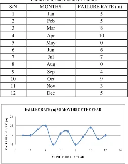
[image:3.612.313.566.190.513.2]The Table I show the numbers of time of failure of the spur gear in study from the period of January-December 2014 and Fig. 3 also show the plot of failure rate vs. months of the year.
Table I.
Failure rate and month of failure
S/N MONTHS FAILURE RATE ( n)
1 Jan 5
2 Feb 5
3 Mar 8
4 Apr 10
5 May 0
6 Jun 6
7 Jul 7
8 Aug 0
9 Sep 4
10 Oct 9
11 Nov 3
12 Dec 5
Fig 3: Showing plot of failure rate versus month which failures occur
The modeling procedure consists of a set of governing equations which were derived from stress equilibrium equations and solved analytically using the polar coordinate system for both radial and thermal stress. The final equations were obtained based on the following assumptions:
1. 1-dimensional stress in the radial direction and 2. 1-dimensional stress in the direction
CASE1:The study considered a case where the temperature distribution is constant throughout the tooth of the gear i.e.
T normal temperature in degree Celsius
Minimum temperature in degree Celsius
CASE 2: The study also considered a case where temperature varies with the radius that can be represented in a form
for both hoop and radial stress Where:
T normal temperature in degree Celsius
Minimum temperature in degree Celsius
Constant r= radius of the gear
CASE3: The study also considered a case where temperature varies non-linearly with the radius in a form that can be represented with the equation for both hoop and radial stress
Where:
T normal temperature in degree Celsius
Minimum temperature in degree Celsius
Constant
Constant r= radius of the gear
B. Gear material and properties
The gear material investigated is mild steel and the following properties of mild steel were used in the simulation.
=Young Modulus of elasticity obtained as 210000 MPa. =density obtained as 7850
=
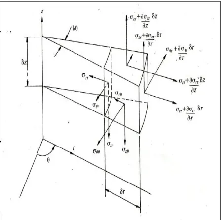
[image:4.612.48.273.478.701.2]=Poisson ratio of mild steel given by 0.303 approximately. Fig. 4 models a finite element of stress variation around a gear tooth in the cylindrical coordinate system acting on its surfaces.
Fig 4: Variation of stresses over a small element in a cylindrical polar coordinate system
Considering equilibrium in the radial direction, the resultant radial force on the element due to the variation of is:
Neglecting the terms involving products of more than three coordinate increments, this expression simplifies to:
Due to the hopper stresses acting on the sloping sides of the element, there is a resultant radial force of
Since for small values of
As result of the variation in the shear stress in the
direction, the radial force is
Thus as a result of the variation in shear stress in the Z
direction
For the local acceleration of the element in r direction, equation 6 results:
If the local body force per unit volume is , and since the volume of the element is approximately the total body force is
The stress equation of small motion in the radial forces is given by:
This gives:
Similar derivatives were obtained in the hoop and axial direction as:
For the case of symmetry about the Z-axis,
The variables with respect to the angular coordinate, , were set to zero, together with the shear stress and body force
in equations (9).This then gives:
From equation (9)
Applying the biharmonic stress function:
(13)
The general biharmonic governing differential equation is given by:
That is;
Case 1: Assuming that there is no significant variation of stress in the axial direction we have;
On integrating equation (16):
But
=
So
(19)
For rotating gear,
Thus,
=
Also,
The quantity
because it is small and negligible
So,
Subtracting equation (23a) from (23b)
For constant ‘C’, substitute “A” into equation (23a)
−3+ 8 2 02− 2− 02− 2 02 2
(25)
Substitute equations (24) and (25) into equations (22)
Recall that,
(22)
,
,
(23c)
(23d)
To obtain C substitute A into equation (23c)
−1+3 8 2 2− 2− 1 2−1 2
−1+3 8 2 2− 2
Substituting the values of A and C into Equation (22)
1 2−1 2 +2 121+3 8 2 2− 2+
1 2−1 2 + 1+3 8 2 2− 2+
2 2− 2 − − −1+3 8 2 2− 2
a. Modelling for the radial-thermal stress CASE 1:
CASE 2 :
2− 2 2. 2 2− 22+ 3− 331 2+ +3+ 8 2 2+ 2+2 2 2− 2+ 3− 33− 2. 2 − −3+ 8 2 2− 2 2− 22+ 3− 33
CASE 3:Equation for
2− 2 2. 2 2− 22+ 3− 33+ 4− 441
2+ +3+ 8 2 2+ 2+2 2 2− 22+ 3−
33+ 4− 44− 2. 2 − −3+ 8 2 2− 2 2− 22+ 3− 33+ 4− 44
b. modeling for hoop-thermal stress
Case 1:
1 2−1 2 +1+3 8 2 2− 2+ 2 2− 2 − − −1+3 8 2 2− 2
1 2−1 2 +1+3 8 2 2− 2+ 2 2− 2 − − −1+3 8 2 2− 2
1 2−1 2 22+1+3 8 2 2− 2+ 2 2− 2 − − −1+3 8 2 2− 2 22
Case 2:
1 2−1 2 22+ 33+1+3 8 2 2− 2+ 2 2−
2 − − −1+3 8 2 2− 2 22+ 33
Case 3:
IV. RESULTS AND DISCUSSSION For Radial stress results:
[image:8.612.46.233.74.265.2]Case: 1
Fig. 5: Radial stress versus depth distance below surface
[image:8.612.312.498.76.268.2]Case: 2
Fig. 6: Radial stress versus depth distance below surface
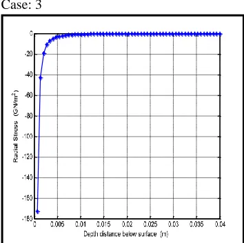
Case: 3
Fig. 7: Radial stress versus depth distance below surface
[image:8.612.46.224.306.481.2]For Hoop Stress Result Case 1
Fig. 8: Hoop stress versus depth distance below surface
Case: 2
.
Fig 9: Hoop stress versus depth distance below surface
Case: 3
[image:8.612.312.498.307.472.2] [image:8.612.314.496.515.702.2] [image:8.612.46.223.521.697.2]Fig. 5 shows that at the point of contact the compressive stress is approximately 178 GPa. This stress decreases along the depth of the gear tooth inward until a depth of 0.53 cm where it becomes constant at 0 GPa. Beyond this depth, the tooth material experiences no stress effect. It is therefore obvious that if the gear tooth needs to be hardened, it is at the tip and the distance as stated before
Fig. 6 represents the case of linear variation of temperature distribution with the radius of the gear tooth as earlier represented with an equation for case 2 for radial stress. It can be deduced that the figure is an exact replica of Fig. 5 even though the temperature distribution varies linearly with the tooth radius. The same result would be achieved. However the reverse is the case for a non linear variation of temperature distribution with radius
Fig. 7 represent the third case of temperature distribution varying non-linearly with the radius of the gear tooth which also has its equation named as case 3 for radial stress distribution. The effect of non-linearity of temperature variation was felt much more in depth. The compressive stress travels deeper than when the temperature was either constant or varied linearly. Thus while there were no stress effects at a depth of 0.53 cm for constant and linearly varied temperatures, the stress effect for non linearity in temperature variation travelled up to the depth of 1 cm. Hence, the nonlinearity temperature variation makes the material susceptible to penetrating stress. Moreover, since the tooth surfaces undergo fluctuating, and cyclic stresses of all kinds during the course of action, fatigue failure of the surface may ensues.
In comparison with the result of hoop stress, Fig. 8 is a plot representing the changes in hoop stress with depth along the tooth distance .This also represents the case where temperature is assumed constant on the tooth. It could be observed as well from Fig. 8 that at the point of contact, the compressive stress is approximately 0.212 Gpa. This stress decreases along the depth of the gear tooth inward in a circumferential manner until a depth of 0.2 m where it becomes constant at 0.084Gpa. Beyond this depth, the tooth material experiences less stress effect.
Similarly Fig. 9 illustrates the plot for a case 2 for hoop stress which is also a case of linear temperature variation for hoop stress. The effect of linearity in temperature variation is not obvious as earlier observed for case 2 of radial stress since the plot takes the same shape as well as the same values for maximum stress and depth responsible for the tooth deformation.
Fig. 10 represents a plot for the case of nonlinearity of temperature variation for hoop stress, from the result compressive stress is also felt deeper compared to the constant and linearity cases for temperature variation. The stress effect
for the nonlinear variation in temperature is felt up to the depth of 0.24m. It is therefore also possible to say that the nonlinearity variation in temperature has more stress effect. A common observation from the three plots for hoop stress revealed that all the plots appeared to have the same decrease and increase in stress towards the plastic region which signifies the effect of nonlinearity in temperature variation as well as variation in the tooth radius as the stress moves inward.
In general circumferential (hoop) and radial stresses are responses to diametrical deformation. The hoop stress is stress in the direction along the circumference, and the radial stress is a stress in the radial direction. In gear teeth, there is a distribution of tangential and radial stress across the thickness of the gear tooth. However, when the wall thickness of the gear tooth is less than 1/20th of the radius according to Shigley the distribution has a valid approximation of an average hoop stress. As well, the radial stress tends not to matter much because it is so small when compared to the hoop stress. The hoop stress then becomes the driving factor for gear tooth design or analysis.
V. CONCLUSIONS
Analytical techniques have been used to determine radial and hoop stress effect on a spur gear with the considerations of constant, linear and nonlinearity in the variation of temperatures on the gear tooth.
The result revealed that the nonlinearity in temperature variations for both radial stress and hoop stress have more thermal effect on the spur gear tooth compared to the constant and linear temperature variation.
In general, it has also been demonstrated from the results of hoop stress that it has more impact when compared to the radial stress.
ACKNOWLEDGMENT
The authors wished to acknowledge the management of Covenant University for their part sponsorship and contribution made to the success of the completion of this research paper.
REFERENCES
[1] Ajayi O. Oluseyi Lecture on “Design and Advanced Engineering Research” Mechanical Engineering Department School of postgraduate studies, University of Lagos Akoka Nigeria. 2012
[3] Kahraman, A., “Dynamic Analysis of Geared Rotors by Finite Elements”,Journal of Mechanical Design, 114 (September), pp 507-514, 1992,.
[4] Fredette. L and Brown. M., “Gear Stress Reduction Using Internal Stress Relief Features”, Journal of Mechanical Design, vol. 119, pp. 518-521, 1997.
[5] Ashwini Joshi, Vijay Kumar Karma, ”Effect on Strength of Involutes Spur Gear by Changing the Fillet Radius Using FEA”, International Journal Of Scientific & Engineering Research, Volume 2, Issue 9, September 2010.
[6] M.S.Hebbel, V.B.Math and B.G.Sheeparamatti, “A Study on Reducing the Root Fillet Stress in Spur Gear Using Internal Stress Relieving Feature of Different Shapes”, International Journal of Recent Trends in Engineering, Vol. 1, No. 5, May 2009.
[7] Ali Raad Hassan, “Contact Stress Analysis of Spur Gear Teeth Pair”, World Academy of Science, Engineering and Technology 58 2009.
[8] Hariharan M.E Thesis, “spur gear tooth stress analysis and stress reduction using stress reducing geometrical features”, Thapar institute of Engg. & Tech., 2006.
[9] Zhong Wan, Shaojun Zhang “Problem of Spur Gear Drive and its Global Optimization”School of Mathematics and Statistics, Central South University China.
[10] V.Siva Prasad, Syed Altaf Hussein, V. Pandrangadu ,K .PalaniKumar “Modelling and Analysis of Spur Gear for Sugarcane Juice Machine under Static Load Condition by Using FEA” PG students, School of Mechanical Engineering RGM college of Engineering and Technology, Nandyal, India [11] M. Savage, S.B. Lattime, and J.A Kimmel “Optimal Design of
Compact Spur Gear ReductionsThe University of Akron, Ohio [12] Salawu Enesi Yekini , Oluseyi O. Ajayi, O.O Olatunji
“Theoretical Modelling Of Thermal-Hoop Stress Around The Tooth Of A Spur Gear In A Filler MachineJournal of Multidisciplinary Engineering Science and Technology (JMEST) ISSN: 3159-0040 Vol. 2 Issue 7, July - 2015