Technology
An Overview for the
Data and Telecommunications Industries
By
Edward Cooper
Sytek, Inc.
Mountain View, California
Sytek
Sytek Press 1225 Charleston Road Mountain View, California 94043
Book Design: . Richard Klein Design, Inc. EditoriallProduction Supervision:
Diana Drew
Cover Illustration: Robert Pleasure Interior Illustrations,: Gemini Graphics Text Typesetting: George Graphics Manufacturing Buyer: Ed a'Dougherty
Copyright © 1986, 1984 by Sytek, Incorporated
This 1986 edition published by Prentice-Hall, Inc.
A Division of Simon & Schuster Englewood Cliffs, New Jersey 07632
All rights reserved. No part of this
publication may be reproduced, stored in al
retrieval system, or transmitted, in any form or by any means, electronic, mechanical, photocopying, recording or otherwise, without the prior written permission of the publisher.
Printed in the United States of America
10 9 8 7 6 5 4 3 2 1
ISBN 0-13-083379-7
025
Prentice-Hall International (UK) Limited,
London
Prentice-Hall of Australia Pty. Limited,
Sydney."
Prentice-Hall Canada Inc., Toronto
Prentice-Hall Hi~panoamericana, S.A.~
Mexico "" '
Prentice-Hall of India Private Limited;
New Delhi
Prentice-Hall of Japan, Inc., Tokyo
Prentice-Hall of Southeast Asia Pte.jUd.,
Singapore,.
,l
organizations began buying and using these systems. At the same time, corporate electronic data processing departments made remote access to their centralized computers possible by distributing terminals and other input/output devices throughout the company's offices.
The problem of connecting many terminals, printers, and other remote peripheral devices to a large, centralized computer was solved by using point-to-point multi-conductor cables, modems with telephone lines, and even dedicated coaxial cables. These techniques led to wiring mazes and maintenance problems in even medium-sized plants and office buildings. A bettq:r solution to the interconnection problem was developed by combining the technologies of broadband cable communications and programmable microprocessor and interface circuits. This same approach was also used to connect separate personal computers and workstations together into local area networks (LANs). Broadband networking allows many different devices to be
connected throughout a large area with a single cable.
Broadband radio frequency (RF) coaxial cable systems have been in service since the 1950s. The designs, components, and tools for such systems have been developed and refined by several different companies. Mass production has lowered the cost of broadband cable components greatly. Similarly, the cost of intelligent interface devices has dropped because of continuing advances in the semiconductor industry.
Broadband local area networks can now be used to link sophisticated data processing equipment, and can provide a reliable communication backbone for transmitting audio and video signals throughout a facility. Data transmission became practical with the development of the RF modem, which translates digital data into RF signals and vice versa. A packet communication unit that combines an RF modem with a standard RS-232 interface port permits data transfer among digital devices from many different vendors.
This book will help managers, engineers, and operators involved with data communications to understand the principles and techniques of broadband networks.
by reading books.
Readers desiring to gain an overview of broadband communications should begin with chapter one. Technical personnel might skim over the first chapter, read chapters two and three, and concentrate on the detailed information in chapters four, five, and six.
Chapter one provides general information on the development of broadband systems and their applications, especially in local area networks.
Chapter two discusses several topics that are important in understanding broadband networks.
Chapter three contains details regarding different cable system architectures that are currently used, including a comparison of single and dual cable systems.
Chapter four describes characteristics of the active and passive components that comprise broadband networks.
Chapter five covers system-level design problems that must be solved for each network. Sample calculations show how various design factors interact with each other.
Chapter six includes details on system alignment procedures, common problems that can occur, and possible solutions to these problems.
Chapter seven lists sources of further information.
The appendices following the text contain specific references to terms and symbols, CATV system frequencies, tools and test equipment, equipment
manufacturers, and books in the field. Details of RF calculations and system grounding are also included.
For additional information consult the reference materials listed. To discuss your specific requirements please call the Cable Design and Consulting Group of Sytek, Inc., Mountain View, California (415/966-7347). In addition, we hope to continue to provide informative overviews, such as this one, in other areas of broadband communications.
We would like to thank the many people who contributed their time and
knowledge in making this book. In particular, Linda, Richard, and Cheralynn Cooper, who had to put up with Ed's typing on a terminal for several weeks. Christopher's parents, Louis and Josephine Poda, have provided support and encouragement which is greatly appreciated.
Mike Pliner of Sytek provided the necessary support for the extensive effort that was required. Several other individuals provided suggestions on the format and technical content: Helmut Hess and Cecil Turner of the RF Systems Division of General Instrument Corporation; Ken Howell of TRW; and Marcia Allen, Mike Kalashian, Peter Filice, and Don Koller of Sytek, Incorporated. Ralph DeMent of DEC, and all our professional contacts encouraged us to write this overview. Allen Day, Susan Lindsay, and Michele Bisson were very helpful in the design and production process.
Welcome to the world of broadband communications!
Contents
1. Background and Applications 2
Introduction .' 2
Broadband Communications. 2
The CATV Connection. 3
Coaxial Cable . 4
Frequency Multiplexing. 4
Geographic Independence 6
The Business Community .. 6
Office of the Future .. 7
Work-at-Home . . . . 7
Small Businesses 7
The Industrial Community. 7
The Educational Community 8
Network Examples .. 9
2. Key Broadband Concepts . 12
Introduction 12
Network Topology 12
Physical Topology .. 12
The Headend 13
The Distribution Network 14
Logical Topology. 14
Network Implementation: Single and Dual Cable Systems. 15
Components 18
Design Issues . . 19
Achieving Proper Signal Levels 19
Signal Amplitude: the Decibel (dB) 20
Unity Gain Trunk Design 22
System Losses .. 22
Transparent System Design . 24
Summary. 25
3. Single and Dual Cable Systems . 28
Introduction 28
Single Cable Systems . 28
Subsplit System. 28
Highsplit System. . ... . Converting From A One-Way To A Two-Way System .. Dual Cable Systems . . . . ... .
CATV Dual Trunk Systems . . . .. . ... . Connecting Networks Together.
Comparing Single and Dual Cable Systems . System Bandwidth
Multiple Cable Systems. Amplifier Capacity Components.
Installation . Maintenance ..
Interface to Other Networks Redundancy.
Outlets
Future Developments. Conclusions ....
4. Broadband Components . Introduction
The Coaxial Cable ... Types of Cables ..
Trunk Cables ... Feeder Cables
Drop Cables ... . Installation Considerations
Cable Attenuation.
Frequency Variation. . ... . Temperature Variation ... .
Amplifiers ... . General Amplifier Characteristics.
Amplifier Gain Control. Types of Amplifiers
Trunk Amplifiers ..
Bridging Amplifiers. . ... .
Line Extender Amplifiers ... . Internal Distribution Amplifiers .
Amplifier Module Additions. Attenuators .
Bidirectional Amplification ... . Equalizers . . . Feeder Disconnect
Power Supplies ... . Grounding .. .
Passive Components ... . Connectors and Hardware ... .
Introduction
Initial Considerations. System Structure.
System Frequency Considerations . Bandwidth Requirements ... .
Closed Circuit Television (CCTV) Data Communications.
Special Services ... . Television Distribution
Bandwidth Allocation. Physical Layout.
Signal Levels .
The Video Reference Level Narrow Bandwidth Carrier Levels Narrow Bandwidth Advantages Noise Level
Noise Figure ..
System Carrier-to-Noise Ratio ... . Noise at a Splitter /Combiner
Amplifier Selection
Design and Performance Calculations. Amplifier Gain ... .
Amplifier Cascade. . . ... . Amplifier Output Level ... . System Noise ...
Intermodulation Distortion The System Level Graph
Using the System Level Graph. Reliability and Redundancy
Broadband Component Quality Periodic Maintenance.
Equipment Replacement and Repair ... . Redundant Trunks and Components ... . Status Monitoring Systems
Technical Control Systems. Headend Design .
System Diagrams. Standard Headend .
Large CATV Multichannel Headends .. Composite Triple Beat Distortion .. Harmonically Related Carriers. Interval Related Carrier.
6.
Drawing Standards. System Specifications. Summary.
System Alignment.
Introduction .. . ... . The Need for Alignment ..
Test Equipment Required Documentation ... Coaxial Cable Certification .. Alignment Methods ...
Flat Amplifier Output. Flat Amplifier Input. Flat Midspan ... . Summary ... .
Alignment of Single Cable Two-Way Systems Non-amplified System .. .
Forward Path Alignment .... . Return Path Alignment . Alignment of Dual Cable Systems .
Inbound and Outbound Cables. Potential Problems and Solutions.
Radiation and Signal Ingress . Checking an Outlet ..
Monitoring System Performance Summary.
7. For Further Reading
Appendix A: Definition of Terms
Appendix B: Abbreviations and Acronyms
Appendix C: Broadband Symbols
Appendix D: Frequency Allocations
Appendix E: RF Calculations
The dBm and dBm V ... . Noise
Carrier-to-Noise Ratio Broadband Design Equations
Appendix F: Test Equipment ..
Appendix G: Tools for Installation and Maintenance Trunk Cable Tools
Figures
Appendix I: System Grounding Introduction
Broadband System Grounding Grounding Between Sites Above Ground Exposed Trunks Ground Loops
Conclusion
Appendix
J:
RF Connector DetailsAppendix K: Bibliography
Appendix L: dBm V-to-Voltage Conversion Chart
Index
1-1. Broadband Coaxial Network in a Dispersed Facility 1-2. Multiple Services Using a Broadband Network 2-1. Inverted Tree Network Topology
2-2. Bidirectional Communication: Frequency Translation
2-3. Bidirectional Communication: Full Duplex Transmission Paths 2-4. Unity Gain in a System
2-5. Unity Gain of One Stage
3-1. Typical Two-Way Cable Trunk Amplifiers 3-2. Dual Cable System Amplifier
3-3. Interconnecting LANs with Industrial Trunking 3-4. Combined Single and Dual Cable Systems 4-1. Terminology for Coaxial Trunk Cable 4-2. 0.500-inch Cable Loss
141 141 141 141 142 142 142 144 148 150 152 5 6 13 15 17 22 23 30 32 33 34 42 45 4-3. Cable Attenuation Versus Frequency for Various Sizes of Coaxial Cable 46
4-4. Trunk and Bridging Amplifier 49
4-5. Power Supply Configuration 52
4-6. Insertion Loss Values 53
4-7. Connector Types 55
4-8. Directional Aspects in Cable Systems 56
4-9. The Multi-Tap 57
4-10. The Multi-Tap and Distribution Legs 58
4-11. Amplitude/Frequency Response of Typical Filters 59
4-12. Terminator Symbols 60
5-1. Frequency Allocation Charts 69
5-2. Signal Levels from Trunk to Outlet 71
5-3. A Typical Television Channel 72
Tables
5-5. Television and Data Carriers ... . 5-6. Noise at a Splitter /Combiner ... . 5-7. A Typical System Level Graph
5-8. Headend Configuration Showing Signal Levels 5-9. Typical Cable Distribution Scheme ... . 5-10. Detailed Headend Configuration
6-1. Trunk Amplifier Configurations .. 6-2. Amplifier Alignment Techniques 6-3. Forward Path Alignment ... 6-4. Signal Levels at a Junction C-l. Broadband Symbols
D-1. Frequency Allocation Chart
J-1. Terminology for Connector Parts ... . J-2. Connector /Equipment Interface
J-3. F Connector Types and Parts
2-1.
2-2.
5-1. 5-2. 5-3. 5-4. D-l. F-1.
Bidirectional Single-Cable Systems
dBm V /Microvolt Conversion Chart ... . Effect of Cascading Amplifiers on Noise Figure
Picture Quality for C/N Values ... .
Sample System Design Characteristics ... . Broadband System Specifications ... . Headend Channel Assignment Reference Table
Test Equipment for RF Network Certification
74 78 85 90
91 92 101 105 107 109
127
128 144 146
147
16 21 76
77
82
In trod uction
Over the past decade, electronic data communication requirements have exceeded the capacities and capabilities of existing telephone, twisted pair, and similar
communication media. Continuing advances in data processing, new developments in interactive equipment, and expanding network implementations impose further strains on conventional wiring schemes. Techniques using standard twisted pairs are cumbersome when the system requires:
~ Frequent expansion or reconfiguration ~ Complex central intelligence
~ Flexible equipment placement and data flow
In addition, these techniques cannot distribute real time, high quality video signals for video conferencing and security applications. The office of the future and the wired city
concepts would require multiple, overlaying wiring schemes, if they were to be implemented using conventional wiring.
The problems faced by many facility managers are further compounded by the complex wiring necessary to provide each building with contemporary systems for communication (voice, video, and data), emergency detection and warning, and equipment control. As a result, ceilings bulge from the weight of many twisted wire cables, telephone lines, and dedicated coaxial cables installed to provide current and future services.
Fortunately, advances in cable television technology have led to the development of a multi mode broadband signal distribution technique. This technique requires only a single coaxial cable to carry many different signals simultaneously. A broadband local area network (LAN) provides reliable, inexpensive, wideband communications within a single building or throughout a dispersed site such as a campus or an industrial park.
This chapter discusses broadband communications in general, including its origins and applications.
Broadband Communications
Broadband is a generic term that refers to a type of wide bandwidth communication
~ Pi.. broadband network is a communications utility that can be used by many different services; it provides the backbone for an integrated information system throughout the area it serves.
~ Information signals modulate RF carrier signals that are transported by coaxial cable.
~ Many different types of information signals can share the cable's wide bandwidth (several hundred megahertz) by frequency division multiplexing (FDM).
~ Each FOM channel can be subdivided further by using a variety of channel access techniques, such as time-division multiplexing (TOM).
~ The network is geographically independent: devices can be attached to the network anywhere and operate correctly.
~ The network is robust. The failure of an interface device attached to the network cannot prevent the entire system from operating.
One early application of broadband communications was to provide television signals to remote areas via coaxial cable. The components and network design principles developed for these cable television systems have been directly applied to broadband local area networks.
The CATV Connection
Community Antenna Television (CATV) systems began operation in 1949. The CATV operator built an antenna site and a coaxial cable distribution network. The antenna site received distant broadcast television signals. The cable distribution network connected the antenna site (or a separate signal distribution facility) to each customer's house. Television signals were received, processed, and transmitted along the cables to viewers. Cable transmission was used in locations that could not receive broadcast transmissions directly because of distance or because of interfering buildings or terrain.
These early systems were limited in the services and Signal quality they provided. Many system operators were satisfied if they could receive, amplify, and deliver a signal to locations where it could not be received directly. Since most television viewers were within reception range of at least one broadcast station, CATV systems were confined to serving small, remote areas of the country.
In the past decade the CATV industry has grown greatly. Operators attracted new customers by offering additional channels and new services that were not available from broadcast television stations. In 1982, the cable television industry served 21 million subscribers. By the end of 1989 that figure is predicted to rise to 65 million (more than thirty percent penetration of the available market). This potential customer base encourages greater investment in new technologies. New research and
development will bring lower equipment costs and more services to both CATV and broadband local area networks.
primarily unidirectional, although two-way transmission capability is becoming more popular. Bidirectional CATV systems can supply customers with additional services, such as data communications and interactive videotext.
Coaxial Cable
As a signal distribution medium, coaxial cables are reliable, economical, and can be installed in existing conduits, underground cableways, and plenums. Coaxial cables are available in several types, suitable to various environmental conditions. If damaged or broken, the cable can be spliced or short sections can be replaced quickly by semi-skilled personnel using simple tools.
Coaxial cables provide excellent shielding from electromagnetic interference (EMI) and radio frequency interference (RFI). They are ideal for use in electrically noisy industrial environments, where twisted pair wires are difficult to use effectively.
Fault isolation in a coaxial network is straightforward using readily available test equipment. The isolation process can be enhanced by automated statistical recall systems, status monitoring facilities, and programmable spectrum analyzers and signal generators.
Frequency Multiplexing
Frequency multiplexing permits simultaneous use of the cable by many different services. The large bandwidth available on the cable is divided into channels, usually 6 MHz wide. One channel can be used for transmitting video from a local camera, while another channel can carry data between a computer and a terminal. These applications can be totally independent yet use the same cable as their communication medium.
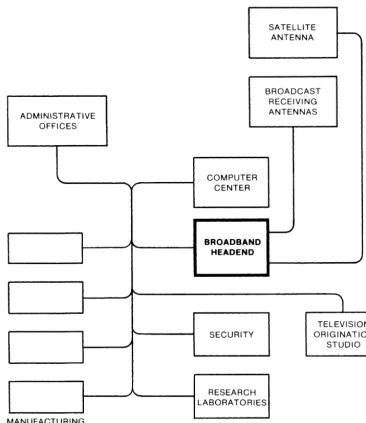
The following list mentions some typical applications that can share a single broadband local area network. Some require only one-way communication and others require a two-way capability. Careful planning of equipment to be purchased and frequency assignments to be made is necessary to ensure proper operation and no spectrum conflicts. Figure 1-1 depicts a broadband network connecting all the buildings inside a single facility. Figure 1-2 shows some of the services that could use this network.
~ Data communications
~ Broadcast television signal distribution ~ Video conferencing
~ Security and safety monitoring I> Fire alarms
I> Intrusion alarms
I> Closed circuit television (CCTV) surveillance cameras I> Remote television camera control
I> BUilding and area access control
~ Paging
SATELLITE
ANTENNA
r--.
BROADCAST RECEIVING
ADMINISTRATIVE ANTENNAS
OFFICES
COMPUTER CENTER
~ BROADBAND
HEADEND
1
TELEVISION
SECURITY ORIGINATION
STUDIO
RESEARCH LABORATORIES
[image:16.645.227.593.67.489.2]MANUFACTURING COMPLEX
RFMODEM FOR CONTROL,
VIDEO CONFERENCING
OTHER VIDEO
~ CAMERA ANTENNA
VTR VCR
BROADBAND COAXIAL COMMUNICATIONS NETWORK BUS
STUDIO TELEVISION MONITOR RECEIVER
SENSORS
...-, _ _ _ _ _ _ _ _ - - , TERMINALS PUBLIC ADDRESS SENSORS
[image:17.642.224.590.78.370.2]~
M = MODULATOR C = CHANNEL PROCESSOR D = DEMODULATORFigure 1-2. Multiple Services Using a Broadband Network
Geographic Independence
Geographic independence means that a device performs as specified regardless of where it resides in the network. When a building is fully wired with coaxial cable, devices can be attached anywhere a standard outlet has been installed. This allows, for example, a data communication user to disconnect an interface unit, move to a different office, reconnect the device to the cable outlet, and resume working with no need for additional wiring changes.
The cost of conventional wiring to provide an equivalent, multiservice capability with the same flexibility would be much greater than that of a single coaxial cable. For each of the services to be provided, the conventional scheme would require many dedicated wires and cables throughout the building, some overlapping others. With broadband, any type of device for any type of service could be placed wherever the single coaxial cable was accessible. A complex color television camera, a simple smoke detector, and many other devices connect to the same coaxial information utility line.
The Business Community
created a need for some method to convey information throughout offices, between buildings, and to more distant locations quickly and reliably. Three different areas that could prosper from broadband networking are the office of the future, the work-at-home
concept, and small businesses. Broadband technology provides the necessary resources
and interfaces to meet the local, regional, and national requirements of these and other business communication applications.
Office of the Future
The aim of introducing advanced technology into the office workplace is to improve productivity. Productivity in offices has not kept pace with that of factories, where tremendous improvements have resulted from automation. Office automation is spreading in large and small companies; it includes the use of word processors, facsimile machines, intelligent copiers, computer terminals, and video conferencing equipment.
Broadband networking can provide an integrated solution to the problem of how to convey all the needed information to all the devices providing these services. Once the network is implemented, additional services can be added such as electronic mail, high-speed data transfer between workstations, integrated energy management, and access control.
Work-at-Home
The work-at-home concept has been popularized over the past several years. However, the high costs of implementing the required network and providing a home terminal slowed its growth. Terminal costs are predicted to soon be in the $250 range, making them cost effective for many users. Product announcements by major manufacturers indicate the cost of network implementation is also dropping rapidly.
Small Businesses
Networking in the small business sector could proVide the impetus for the greatest integration of CATV and broadband local area networks. Thousands of companies throughout the United States could use individual broadband networks to supply their local requirements. These local networks could interface to CATV industrial trunks that supply communication links with other buildings (which could be several miles away).
The costs would be lower and the capabilities greater for a system using a broadband approach, compared to one using conventional wiring schemes for local networking.
The Industrial Community
The growth of factory automation has been tremendous over the past several years. This trend will continue as more intelligence is placed inside machines used directly on the factory floor, and as robots become commonplace in both large and small shops.
material, workpieces, and assemblies. Each machine must be programmed, and must provide various status signals back to the operator. A factory floor status reporting system can add further data on specific jobs and parts flow through the facility. Connecting all these devices together with a broadband network can provide the following advantages.
~ More efficient use of machinery
~ Improved scheduling of work and maintenance ~ Better reporting of results
~ Closer monitoring of machine performance
~ Tighter control of factory performance and costs
A single broadband network can link a factory and an office to the automated data processing systems that support modern business operations. This integrated approach can provide timely information for all the following applications.
~ Accounting
~ Personnel management
~ Time and attendance measurement
~ Energy management ~ Assembly line automation
~ Program and schedule. verification
In addition to providing a wide bandwidth medium that can be used by many different services, broadband coaxial cable is much less susceptible to electrical noise than twisted-pair wires. Both industrial and office environments contain radio frequency interference that could degrade the performance of a network and terminal equipment. It is best to assume the ambient levels of interference will become even greater, and to design networks protected to work properly under those conditions.
The Educational Community
Educational institutions are finding the broadband approach a reliable, economical, and efficient way to satisfy their communications requirements. These facilities have several unique needs that can be met by broadband networks.
~ The wide geographical extent of a large campus can tax any communications system attempting to serve the whole area. Broadband networks have been successfully covering wide areas for years.
~ Cost constraints demand a network that is low cost, easy to maintain, and vendor-independent. Broadband satisfies all three of these criteria.
1. The user is not limited to purchasing equipment from only one or a few vendors.
2. Many different types of equipment can be connected together over a single medium. The user can select terminals, workstations, and other devices from a wide range of available units, and choose those that provide the best cost and performance tradeoff for a specific application.
~ Real-time video must be provided throughout the campus for closed-circuit television courses. Several one-way full bandwidth television channels can be reserved on the cable for this purpose.
~ Other services could use the coaxial cable and minimize the installation and maintenance costs for communication services throughout the campus.
~ Televised classes in the local community could be conveyed from the campus's broadband network to the city's local CATV network. A two-way path between these two networks could provide the campus with additional video signals from broadcasters and from other educational facilities.
Institutions including Brown, Cornell, Carnegie-Mellon, and the University of Waterloo have made extensive telecommunication studies, concluding that broadband distribution is a feasible and cost-effective approach to providing communication services.
*
Network Examples
A fully activated broadband system (one with all return paths active) cannot be duplicated in a large CATV system covering a major city without special consideration. However, the industrial, educational, and business communities have seen few limitations to broadband local area network applications. As an example of possible broadband network size, a network in a West coast industrial plant covers an area greater than 3.6 million square feet of floor space on each of its two floors. Only 11 amplifiers support the entire network, which provides an RF connection within 100 feet of any point in the system.
Another system in the Chicago area provides 4000 RF outlets over six buildings, with no point farther than 20 feet from an outlet. This network also required only 11
amplifiers to support the six buildings, each of which has four floors of distribution. A third example is a single system connecting six buildings. Within this complex, each building has from 9 to 23 floors of high-density outlet distribution (an outlet for each office). Only 21 amplifiers were required in this network. Also, a backup trunk was installed that can be switched into operation either automatically or manually if the primary circuit fails.
All three of these examples have operated successfully without a single amplifier module failure for a total of 12 system-years of operating experience. A broadband
network can be counted on for continuous, daily operation. The high reliability of broadband components makes redundant backup devices necessary only for the most demanding networks.
Introduction
This chapter introduces several important topics that will help in understanding broadband communication systems. Several of these areas are covered in more depth in the chapters indicated below.
~ Topology
~ Implementation (chapter three)
~ Components (chapter four) ~ Design issues (chapter five)
Network Topology
The arrangement of a broadband network is often described in two ways.
~ Its physical topology: where the components are located.
~ Its logical topology (architecture): how the components are connected to each other by the network.
Before discussing these two topologies, the main elements of a network must be defined. Every broadband network has two main elements, a headend and a distribution network.
~ The headend comprises the equipment that collects RF signals from transmitting devices attached to the network, and distributes RF signals to receiving devices attached to the network. The term headend refers both to the location of this equipment, and to all the equipment that performs these functions.
~ The distribution network comprises coaxial cables, amplifiers, and other signal-carrying components that provide signal paths between devices attached to the network and the headend.
Physical Topology
The placement of the headend and the distribution network determines the physical topology of the system. This topology can be portrayed by a map showing the location of these network elements. This map resembles a similar plot of other utility
1. It has a main trunk line that originates at the headend and traverses central areas. 2. It has many branch lines that extend from the trunk to outlying areas.
3. It has individual lines that run from each node on a branch to each connection point.
The trunk and branches form the backbone network. The backbone can usually support thousands of connections to user devices, with drop cables (connections to user outlets) installed as demand dictates (figure 2-1). In a large network, the headend is often located centrally so that the network can be extended easily in any direction.
The nodes of the network are determined by the location of the devices that use network services. Branch cables can be laid to connect the nodes in many different ways. Regardless of the layout chosen, each node connects to the cable system at only one point, and is independent of all other nodes. This structure eliminates any chance of multi-path distortion.
The physical layout of a broadband system can be designed to conform to any building arrangement. The flexibility of the broadband technique exceeds that of any other wiring scheme in use today.
HEADEND
o
BRANCHING POINTSo
USER DEVICESFigure 2-1. Inverted Tree Network Topology
The Headend
~ In a unidirectional CATV system, the headend transmits all the signals the network carries.
~ In a bidirectional broadband system, both the headend and user devices transmit signals over the network.
Any device connected to the network may transmit signals over the network to other devices. However, these signals do not go directly to the destination device. Signals transmitted by devices connected to the network first go to the headend, and are then retransmitted back to the network. Routing all transmitted signals to the headend prevents interference among signals travelling on the system.
Equipment normally found in the headend of a large network that provides multiple services are signal processors, modulators, demodulators, signal combiners, data translation units, and power supplies. These devices are described in references dealing with CATV systems (see bibliography).
The Distribution Network
The distribution network is the combination of components that transfer RF signals between the headend and the attached user devices. These components include the following.
~ Coaxial cables that carry signals between two points.
~ Splitters, directional couplers, and taps that direct signal flow along desired paths. ~ Filters that process signals depending on their frequency.
~ Outlets that connect devices to the network. ~ Amplifiers that increase signal strength.
Chapter four describes these components and their characteristics.
Logical Topology
From the local network point of view, the logical topology or architecture of the broadband network could be a ring, star, or bus. This level of organization is distinct from the physical topology, and depends on the LAN interface devices connected to the broadband network. A single broadband network can support several different types of local networks, each with a different logical topology.
In a bus network, all interface devices may have equal access to the network's resources. This structure requires a method to regulate transmissions and to prevent one device from monopolizing the network. Data communication networks have used such methods, called channel access protocols, for many years.
In a token-passing ring network, each interface device has permission to transmit when it receives a unique pattern of data over the network called the token. This station then transfers its data to the network and passes the token along, when finished, to the next station in the ring.
Other combinations of topologies and operating rules, or protocols, can be used on a broadband network. These communication protocols are provided by the interface devices attached to the network, and not by the backbone network itself. As long as interface devices can successfully get signals on and off the cable, they can send any kind of data using any kind of protocols.
Network Implementation: Single and Dual Cable
Systems
Several different methods are available to provide two-way communication in a broadband network, including single and dual cable systems. Single cable systems carry two-way traffic on one coaxial cable. They provide this bidirectional capability by dividing the cable's frequency spectrum into two main portions, one for traffic in each direction. Dual cable systems use two separate coaxial cables, gne for traffic in each direction.
When using a single cable to carry two-way traffic, the available signal spectrum on that cable is split into three major portions.
~ The forward band carries signals from the headend to devices on the distribution
network.
~ The return band or reverse band carries signals from devices on the distribution network to the headend.
~ The guard band carries no signals, and separates signals in the forward and return
bands.
A dual cable system needs no guard band, since separate cables carry the outbound
traffic (from the headend) and inbound traffic {to the headend}.
Figure 2-2 illustrates frequency translation in a single cable system. Devices attached to the network transmit signals only in the return frequency band. All signals inside the return band are received at the headend and converted up to signals with higher frequencies by a device called a translator. These higher frequency signals, which occupy the forward band, are then transmitted to all receivers on the network.
300 OR 400 MHz
HEADEND EQUIPMENT INCLUDING
DATA TRANSLATOR
5 MHz
Figure 2-2. Bidirectional Communication: Frequency Translation
To visualize this concept, compare the broadband cable to a multilane highway. A highway has lanes going in both directions. The center divider (guard band)
minimizes interference between the two directions and provides a boundary. A single cable supports two-way traffic exactly like a highway. A guard band of several megahertz separates the forward and return bands.
A highway has several lanes in each direction. A broadband cable has several channels for traffic in each direction.
Many different types of vehicles can use the general purpose highway lanes, including cars, trucks, motorcycles, and busses. Many different types of services can use the general purpose broadband channels on the network, including low- and high-speed data, voice, and video.
Some highway lanes can be reserved for specific uses only, such as busses or high-occupancy vehicles. Some channels on the cable system can be reserved for specific uses only. For example, one data communication channel might be reserved for users of a specific time-shared computer that can be accessed only via that channel.
The frequency spectrum of a single cable system can be divided in one of three ways. Each provides a different forward and return bandwidth (see table 2-1).
~ The subsplit format is found on many older CATV systems. It has the least return
path bandwidth of the three. It is usually the easiest format with which to upgrade an existing one-way system to two-way operation.
~ The midsplit format provides more return path bandwidth than the subsplit; it is
often used in contemporary broadband local area networks.
~ The highsplit format is a recent innovation and will become more popular as more
components become available for it. It provides the greatest return bandwidth of these three formats.
All three of these frequency divisions are further described in chapter three.
Table 2-1.
Bidirectional Single-Cable Systems
Format Return Frequency Band Forward Frequency Band
Subsplit 5-30 MHz 54-400 MHz
Midsplit 5-116 MHz 168-400 MHz
Highsplit 5-174 MHz 232-400 MHz
r
I
TRANSLATOR
MODEM
I
~-+--,
I
RETURN PATH
I
t
I
I
,-+-....1
TRANSMIT MODE __ ...._-'
TERMINAL UNIT
•
TYPICAL NODE
•
I
FORWARD PATH•
I
•
i-•
~
•
L·_·_·~·_·_·I
MODEM RECEIVE MODE
•
t
TERMINAL UNIT
Components
The components used in a broadband network can be divided into two categories, active and passive. Active components require input power to operate properly; passive
components do not. Chapter four discusses components in more detail.
The most ubiquitous component in a broadband network is coaxial cable. It is the transmission medium for all signals on the network. A coaxial cable is constructed of a solid center conductor surrounded by a uniform thickness of insulating or dielectric material. These are thoroughly covered by a second layer of conducting material (the
shield) and the final exterior insulation. Both conductors have a common axis, hence
the name coaxial.
Conductor resistance and dielectric conductance are distributed uniformly along the length of the cable, and vary with frequency and temperature. Because of these variations, the frequency response of coaxial cable varies with the following parameters.
~ Length and diameter of the cable ~ Frequency of the signal
~ Ambient temperature
These variations must be considered when designing and installing a system.
Some of the significant characteristics and capabilities of coaxial cable include the following.
~ High bandwidth.
Coaxial cables can convey wider bandwidth signals than twisted pair wiring. Cable bandwidth exceeds that of active and passive RF network components.
~ Shielding.
When properly grounded, the cable's shield (outer conductor) prevents ambient electrical noise from interfering with signals travelling on the center conductor. Thus, coaxial cable is a good transmission medium for use in electrically noisy environments (including offices, laboratories, and factories).
~ Easy connectivity.
A cable can be quickly and easily cut and spliced to repair a break or to attach new outlets, devices, or cable paths.
~ Characteristic impedance.
Most cables used in broadband systems have a 75-ohm characteristic impedance.
~ Diameter.
Larger diameter cables have less loss than smaller diameter cables and are therefore used for main trunks and for long cable runs.
~ Power.
Cables with seamless aluminum shielding can safely transport ac or dc power to amplifiers on the network. By sending power over the cable, each amplifier does not need a separate connection to a power source.
~ Wide selection.
Coaxial cables have been made for several decades by many manufacturers. The technology is well known and the product is reliable. Cables with appropriate characteristics are available for rough environments and other special applications.
Cable attenuation is commonly specified in decibels per 100 feet at the highest operating frequency (300 or 400 MHz for most systems). A typical cable specification provided by the manufacturer could be stated in the following manner.
1.63 dB of loss per 100 feet at 300 MHz measured at 68 degrees Fahrenheit.
This represents the specification of one type of 0.412-inch diameter seamless aluminum coaxial cable.
To calculate the signal loss of a 1000-foot length of this cable, simply multiply 1.63 by 10 which gives 16.3 dB. By using the attenuation factors for each frequency band, the loss of any given length of cable for those bands can be calculated.
Following chapters contain more information on coaxial cables. Chapter four provides further details on their characteristics. Chapter five discusses cable selection.
Design Issues
This section introduces three concepts related to signal levels that are important to the design of broadband networks.
~ Using decibels to indicate signal levels simplifies all network signal level calculations.
~ The unity gain criterion eases system design and alignment.
~ Transparent system design ensures geographical independence of the network.
This discussion points out some of the advantages of properly designed broadband networks. Further coverage of backbone network design is provided in chapter five.
Achieving Proper Signal Levels
every path that each new amplifier affects, and other components might have to be changed to achieve specified signal levels. This process is repeated until all signal levels are within specified ranges.
As an analogy to RF signal distribution, consider a simple water delivery system. The purpose is to provide a specified water pressure to three destinations, which might be done in the following manner.
1. Build a large main delivery line from the reservoir to each location.
2. Install valves at each location.
3. Adjust each valve to deliver the required water pressure. If the pressure is too low, either add pumps or increase the pressure in the main delivery line.
The basic principles of RF design are similar. The main RF trunk cable corresponds to the main delivery line. Passive taps and couplers act like valves that determine the signal level at each outlet. Amplifiers increase signal strength where it is too low.
Signal Amplitude: the Decibel (dB)
Calculating signal levels throughout an entire system can be time-consuming, especially when several channels and amplifiers are involved. This task is made easier by expressing signal levels in logarithmic units.
The decibel is a unit that expresses the ratio of two levels of power. It can also be used to express the ratio of two voltage or current values, if they are measured at points of similar impedance. For example, many network components have an input and an output connection. The ratio of the signal levels at these two points can be expressed in decibels, such as an attenuator with 3 dB of loss, or an amplifier with 20 dB of gain, from input to output.
Number of dB = 1000g (PdP2 )
where PI, P2 are power levels
-V v V 2 are voltage levels
log is the base ten logarithm
A standard unit used in the CATV industry to express signal amplitude is the decibel referred to one millivolt (dBm V).
Number of dBmV = 20l0g (VI/lmV)
where V I = the measured voltage level
Using absolute voltage levels instead of decibels to calculate signal levels requires calculations that become more complex as more components and channels are added to a system. Using dBm V to calClIlate signal levels allows easier manipulation of those values. The gain or loss, in decibels, of a component is added to or subtracted from its input signal level to obtain its output signal level. Also, fractional values can be avoided, since any number between zero and one is represented by a negative number of decibels. For example,
~ A 40-dB amplifier increases its input signal voltage level by 100 times; ~ A 6-dB coupler decreases its input signal level by one-half;
~ A video signal level of 10 dBmV for a specific channel at any given outlet is
3,200
J.Lv.
Because decibels are easy to use, all relevant equipment specifications and signal requirements are expressed in dBm V or dB. The difference between two dBm V values is expressed in dB. For example, a typical carrier-to-noise ratio is 43 dB and can be obtained by subtracting the measured noise floor (in dBm V) from the input signal level of an amplifier (in dBm V). Both the input level and the noise floor are expressed in dBm V, but the mathematical result is expressed in dB. Thus, dB is a ratio while dBm V is an expression of signal amplitude.
Table 2-2 provides a short conversion chart for translating between dBm V and voltage. Appendix L contains a more detailed table. Note that all levels below 1000J.LV (0 dBm V) are negative values.
Table 2-2.
dBmV /Volt Conversion Chart
dBmV Voltage
80 10.0 Volts
70 3.2
60 1.0
50 320,000 J.LV
40 100,000
30 32,000
20 10,000
10 3,200
0 1,000
-10 320
-20 100
-30 32
Unity Gain Trunk Design
When designing the trunk portion of the distribution system, the unity gain criterion should be followed.
Unity Gain Criterion
1. All trunk amplifiers are identical (with respect to noise figure, gain and equalization).
2. All trunk amplifiers are separated by an identical length of cable.
3. Flat Loss
+
Cable Loss = Amplifier Gain.Result: All trunk amplifier output levels are identical.
Designing the trunk to this standard provides these advantages.
~ The system is easy to design by consistently following this rule.
~ The system is easy to align and maintain, since the output levels of all amplifiers are identical.
This rule requires that either each trunk amplifier be adjusted to compensate for the losses between its input point and the previous amplifier:s output point (see figure 2-4); or that each trunk amplifier be adjusted to compensate for the losses between its output point and the following amplifier's input point. Thus each amplifier in the system has the same output signal level, and the system has unity gain throughout (no increase or decrease in signal level from one amplifier's output to the next).
HEADEND
CL ~ CABLE LOSS (dB) FL ~ FLAT LOSS (dB) G ~ AMPLIFIER GAIN (dB)
UNITY GAIN --.jiot--UNITY GAIN --~- UNITY GAIN
V ~ SIGNAL VOLTAGE LEVEL (dBmV)
Figure 2-4. Unity Gain in a System
System Losses
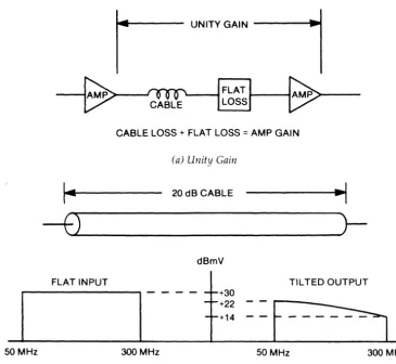
~ Flat loss, or passive loss, is the attenuation through all the passive components in the network (not including the cable). The value of this loss is constant across the entire frequency spectrum.
~ Cable loss is the attenuation of the coaxial cable. This loss increases with frequency, a characteristic called cable tilt.
To achieve the same amplitude for all signals at all frequencies of interest, it is necessary to compensate for both flat loss and cable loss. This is accomplished with equalizers and amplifiers.
An equalizer has an attenuation characteristic that is the inverse of the cable tilt with respect to frequency. It attenuates low frequency signals more than high frequency signals. Ideally, the combined cable and equalizer losses produce constant attenuation across the system's entire bandwidth.
A flat gain amplifier following the equalizer increases signal levels across the spectrum. Figure 2-5 demonstrates unity gain and shows how one stage of a network compensates for cable tilt.
50 MHz
I
UNITIGAINI
>--..fl5lnr\---I
FLAT...----1
LOSS
CABLE LOSS + FLAT LOSS
=
AMP GAIN(a) Unity Gain
I~
20 dB CABLE ... \-f",,--) _ _ _ _ _ _ _ _
)--dBmV
FLAT INPUT TILTED OUTPUT
300 MHz
+30 +22 +14
(b) Cable Attenuation
50 MHz 300 MHz
[image:34.639.228.593.287.622.2]-f1""i)~
___
--=20:=...::d:.=B~C::::A::::B:::L:!:;E
_ _ _ _ _r-1
EQU~~~ER ~
dBmV FLAT INPUT CABLE OUTPUT _ _ :"Q':.A~Z:"R ~U2:P~T _
4-
+301
- -
-cs=:=:::::=:::::::: - - - -
,-+22 - - - +14I
I
T+
6(c) Cable and Equalizer
FLAT
-f'-')"--_ _ _
..:20~d=B..:C:;.A:.:B=L=E
_ _ _ _r___i
EQ~~~~ZER
t---t>-dBmV
FLAT INPUT CABLE OUTPUT EQUALIZER OUTPUT AMP. OUTPUT
- - - -
- -
--
--
- +3 - +2I
- - +1r
1
- - +650MHz 300 50 300 50 300 50 300 MHz
(d) Cable, Equalizer, and Flat Gain Amplifier
Figure 2-5. Unity Gain of One Stage (Continued)
o
2 4
Transparent System Design
During the design phase, a standard signal level should be established for all outlets in a system. When this is done, connectivity requirements for the network are
transparent. Any device can be attached to any outlet and use the same network services, regardless of its location and function. The input and output circuits of a network interface device need be adjusted only once for the standard system levels, after which the device can be used anywhere in the network. Thus, transparency provides the following advantages.
Summary
For example, a network interface device can be moved from one office to another, and plugged into the second office's outlet. At the new location, it can use and provide the same services that it did at the old location. If the network was not transparent, signal level differences at the two outlets might require adjustment of the interface device whenever it was moved.
Many devices designed to communicate over broadband networks are built to receive at a level of
+
6 dBm V, and to transmit at a level of+
56 dBm V (referred to a television visual carrier signal in a 6 MHz channel). By designing the network to accommodate these signal levels, any such device could be used at any outlet without requiring installation adjustments. (Signal levels are covered in more detail in chapter five.)This chapter covered several essential topics in broadband networking. The physical structure of the network resembles a tree. Attached communication devices see it as a bus, a ring, or a star. Channel protocols are used to control access to channels that have more than a single transmitter on them.
Two-way communication can be accomplished with two one-way cables, or with a single two-way cable that has a separate frequency band for traffic in each direction.
The transmission medium for broadband networks is coaxial cable. Many different types of coaxial cables are available that have characteristics to match various
applications.
Introduction
To achieve bidirectional signal distribution, two basic approaches can be employed.
~ Two-way communications over a single coaxial cable, with different frequency bands carrying signals in opposite directions.
~ Two-way communications over dual coaxial cables, with each cable carrying signals in one direction.
This chapter discusses both approaches, shows how they can be be used together, and compares their capabilities.
Single Cable Systems
Two-way communications can be implemented on a single coaxial cable by dividing the available frequency spectrum on the cable into two bands. These bands carry signals in opposite directions, called forward (away from the headend) and return or
reverse (toward the headend). Devices attached to the network transmit to the headend
on the return band, and receive from the headend on the forward band. Currently, three different frequency divisions are used, called subsplit, midsplit, and highsplit. Each provides a different amount of forward and return bandwidth.
When specifying CATV equipment for a network, be aware that manufacturers use slightly different frequencies and bandwidths. Check each component's
specifications to ensure that all equipment in the system is compatible, and that any filters can pass all the signals being transported.
Subsplit System
Most CATV two-way cable systems now in service use the subsplit format.
~ Forward band 54-400 MHz ~ Reverse band 5-30 MHz
~ Total usable bandwidth 371 MHz
However, when more than 12 channels are to be distributed over a single cable system, separate converters are necessary anyway, eliminating this advantage for many systems.
The subsplit format has limited utility when information originates from locations other than the headend. Since only 25 MHz is available in the return direction, only four television signals or their bandwidth equivalent can be transported to the head end at one time. The impact of this limitation depends on the type of equipment used in the network. Microprocessor-based packet communication units available today permit data networks with thousands of users to operate on a single 6-MHz channel.
Midsplit System
Midsplit systems are used in many data communication networks.
~ Forward band 168 to 400 MHz ~ Reverse band 5 to 116 MHz ~ Total usable bandwidth 343 MHz
Midsplit is more popular than sub split for local area networks, because of its greater return direction bandwidth. It can handle high volume two-way interactive
communications including data (both low- and high-speed) and video. The IEEE-802 specification (a standard currently being developed for local area networks) for such networks endorses this format.
A midsplit system's greater bandwidth can be used by one or more services. For example, when using a modem with a bandwidth efficiency of 2 bits per Hertz, a T1 channel (which conveys digital data at 1.544 Mbits/s) occupies only 772 kHz. A midsplit system can provide over 140 such channels in its return path.
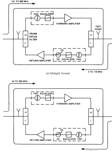
168 TO 300 MHz
IP~ ~u~zffil
~
L ___ -.l
FORWARD AMPLIFIERH TAUNK DIPLEX
_ _ _ ~--L_~-I FILTER
L
RETURN AMPLIFIER
(a) Midsplit Format
54 TO 300 MHz
FORWARD AMPLIFIER
L
RETURN AMPLIFIER
(b) Subsplit Format Figure 3-1. Typical Two-Way Cable Trunk Amplifiers
H
TEST POINT
5 TO 116 MHz
H
L
[image:41.643.217.599.85.600.2]Highsplit System
This is the newest system of the three.
~ Forward band 232-400 MHz
~ Reverse band 5-174 MHz
~ Total usable bandwidth 337 MHz
A high split system fulfills the need for high return path bandwidth that some large systems might have. Some amplifiers are now available in the highsplit format, but standardization among vendors of these units has not yet been achieved.
Converting From A One-Way To A Two-Way System
The following factors should be considered when converting an existing one-way network into a two-way midsplit network.
~ Use of individual frequency converters at each user device. ~ Expandability of present amplifiers to bidirectional use. ~ Redefinition of system frequency allocations.
~ Modification of existing services and their frequency allocations.
~ Selection of passive components that pass all the required frequencies.
~ Inspection of existing coaxial cables. Inspect them to ensure signal ingress will not cause problems.
It is not necessary to disrupt service while upgrading a system to support two-way traffic. Modular amplifier units allow easy installation of return amplifiers, equalizers, and distribution legs in the field.
One study from the cable industry estimates that existing one-way networks can be upgraded to two-way subsplit networks at a cost of around $300 per mile. *
Dual Cable
Systems
Two-way dual cable systems use two coaxial cables laid side-by-side. One cable provides the inbound (return) path signals to the headend. The second cable provides the outbound (forward) path signals from the headend to the attached devices.
~ Outbound band 40-400 MHz
~ Inbound band 40-400 MHz ~ Total usable bandwidth 360 MHz
Not all dual cable networks use this same spectrum. For example, Wang Laboratories' network uses non-standard amplifiers with a bandpass of 10 to 350 MHz.
Each outlet in a dual cable system must have two connections that clearly identify the inbound and outbound paths. In addition, twice as many amplifier units are required to implement a dual cable network, compared to a single cable network.
The term amplifier unit refers to the module that contains the gain block, power supply, equalizers, and any associated circuitry. Currently one vendor supplies all the necessary circuitry for both paths of a dual cable system inside a single module. Shielding and isolation requirements dictated against placing circuitry for both directions inside the same enclosure for many years, until improved isolation methods were perfected.
Dual cable system amplifiers are used in the unidirectional mode with a bandpass of 54 to 400 MHz. Figure 3-2 shows the block diagram of a dual cable amplifier.
RETURN PATH
TRUNKA IN
TRUNK BOUT
[image:43.640.221.597.230.528.2]RETURN AMPLIFIER
Figure 3-2. Dual Cable System Amplifier
FORWARD AMPLIFIER
TRUNKAOUT
TOWARD HEADEND
..
TRUNK B IN
FORWARD PATH
CATV Dual Trunk Systems
The two-way dual cable systems described in the preceding section are not the same as CATV dual trunk systems. CATV dual trunk systems are composed of two one-way trunks laid side-by-side to each subscriber's location. The subscriber selects signals from only one trunk at a time with an AlB switch. This technique was a simple way for early CATV systems to double their signal bandwidth. The AlB switch directs the signals from one trunk to the television receiver and isolates the signals on the other trunk from the receiver. Some CATV operators have converted one of these trunks into a two-way system. When the proper trunk is selected by the user, two-way operation is possible.
Connecting N etwor ks Together
Separate networks connect to a common trunk through devices called gateways (see figure 3-3). These devices can be set to pass only a selected frequency band so that each user can be isolated from other users on the common trunk. One well-known system currently using this approach is in the New York area. Manhattan Cable Television provides a dedicated commercial trunk to serve the banking community in New York's financial district. This trunk is primarily used for passing data from one branch of a bank to another. Other gateways can connect to national data transmission networks
RESIDENTIAL CATV DISTRIBUTION
RING
SEPARATE LOCAL AREA NETWORKS
BUS INSTITUTIONAL! COMMERICAL
OISTRIBUTION
' - - RESIDENTIAL --.-/ CATV DISTRIBUTION
GATEWAY BETWEEN NETWORKS
[image:44.645.224.588.352.634.2]HEADEND FORA BROADBAND LOCAL AREA NETWORK
such as TeleNet and Tymnet and extend the range of a local area network across the country. This technique (called industrial trunking) is primarily used in CATV systems to provide dedicated or shared networks for industrial and business users.
Current technology does not permit two-way transmission over the full extent of a large CATV network. However, one or more portions of a large network can be made bidirectional to provide wide band communication links between nearby sites, such as individual local area networks. A device on one local network needing to access a device on another local network can do so over the CATV trunk (figure 3-3).
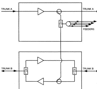
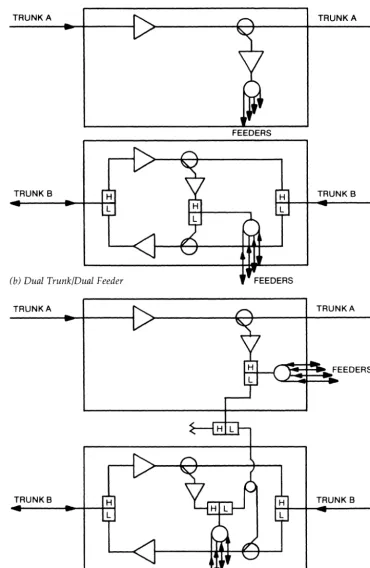
Single and dual cable systems can be combined together into useful network structures. Figure 3-4 illustrates samples of these combinations. At first glance the structures might appear complicated. However, they are simply expansions or reconfigurations of basic single and dual cable structures.
TRUNK A TRUNK A
FEEDERS
TRUNK B TRUNK B
(a) Dual Trunk/Single Feeder
[image:45.642.227.570.243.555.2]TRUNK A
TRUNK B
(b) Dual TrunklDual Feeder
TRUNKA
TRUNKB
(c) Dual TrunklDual Feeder With Crossover
FEEDERS
[image:46.646.225.595.72.640.2]FEEDERS
Figure 3-4. Combined Single and Dual Cable Systems (continued)
TRUNK A
TRUNK B
TRUNKA
Comparing Single and Dual Cable
Systems
This section discusses several advantages and disadvantages of single and dual cable systems to assist in determining where one approach is more suitable than the other.
System Bandwidth
Although it is difficult to generalize for all networks, 60 MHz of bandwidth in each direction has proven adequate for many applications. Several systems use only about 35% of the total bandwidth available.
Where wide bandwidth is necessary, there are two alternatives.
~ A dual cable system can be implemented.
~ Two separate single cable systems, each carrying different services, can be implemented side-by-side.
Two single cable systems provide all the advantages of the single cable method including simpler design, maintenance, and installation, in addition to increased bandwidth and system redundancy. The disadvantages of this approach are cable identification, trunk switching, and more complicated documentation requirements.
When applications require more than about 100 MHz in the return path, it is more cost effective to install two midsplit cables instead of one dual cable system. This provides 222 MHz in the return path and 464 MHz in the forward path.
Multiple Cable Systems
One alternative to a large cable system throughout a facility is to build several distinct and complete systems that serve various subdivisions of that facility. At first glance, this scheme might seem to offer several advantages over either a dual cable or two single cables where large bandwidth is required in the entire facility. However, it has some serious drawbacks.
~ Confusing layout
~ Redundant cabling and equipment
~ Duplication of resources
~ Diffused responsibility for maintenance
A better solution is to have an intra-plant cable trunk that provides the backbone for shared services throughout the entire complex. Connected to this trunk are branches that feed each building. Inside each building, one cable network provides the necessary services. This approach is simpler to design, easier to maintain, and allows better management of system noise.
Amplifier Capacity
assume that one 6-MHz channel contains 56 separate data carriers that use subchannels of 96 kHz bandwidth each. If each carrier is transmitted at a level of
+
56 dBm V, the amplifiers are loaded with the equivalent of 56 separate 6 MHz-wide channels at a+
56 dBm V signal level. All the power capacity of the amplifiers could be consumed by the signals from only 6 MHz of the spectrum, preventing any other signals from being transmitted. In addition, this would distort each amplifier's output signal excessively, and interfering signals could be generated at harmonic frequencies throughout the spectrum.To prevent overloading the amplifiers, narrow bandwidth data signals should be transmitted at lower levels than wide bandwidth video signals. The amount of this signal level difference depends on the number of carrier signals inside a 6-MHz channel. Chapter five contains examples showing how to calculate what is called the
derated carrier level for this situation. These calculations are straightforward, since Single cable networks using the same CATV technology and components have been successfully applied for several years. CATV amplifiers are capable of full channel loading, and the proper operating levels are well known in the industry.
Amplifier loading and data carrier derating can be a problem in dual cable systems where the amplifiers must pass a much wider bandwidth. The proper operating levels for such wideband networks have not been clearly established yet.
Components
Installation
Amplifiers for dual cable systems cost less than those for single cable systems. This is because each dual cable amplifier housing does not hold the extra components (filters and a second amplifier) used by the single cable system. However, twice as many amplifier housings can be required in a dual cable system. Two separate housings are commonly used in most systems.
Most amplifiers for single cable systems operate in standard frequency ranges and with standard bandpasses. Subsplit and midsplit amplifiers are available from many vendors. However, some dual cable systems use different frequencies and bandwidths than others. Amplifiers for such systems might not be available from several sources, which could lead to supply and repair problems.
Dual cable systems do not require the translator that single cable systems need. Interface equipment for dual cable systems must keep signals from the two paths isolated from each other while extracting the data from the RF carriers. Circuits that achieve the necessary isolation can add to the cost of the interface device.
Dual cable systems take up more space than single cable systems because they use twice as much cable, and they need twice as many amplifiers, passive components, and other hardware. When retrofitting an existing facility, mounting space can be critical and the smaller requirements of the single cable system are an advantage.
Maintenance
Repairing both single and dual cable systems is easier if the network has been designed and built with proper components. Maintaining and troubleshooting the single cable network is easier because of its simpler implementation with fewer cables and components. It is easier to follow drawings and trace cables through the single cable plant because there are no directional markings that could be incorrect.
The abundance of cables at every branching point can be confusing when trying to trace the loop from source to destination in a dual cable system. Each piece of cable must be marked correctly throughout the network to minimize the chance of mistakes during connection.
Single cable systems also offer better reliability since they use fewer components.
Interface to Other Networks
Most industrial and institutional trunks provided by the CATV industry are single cable systems. An in-house single cable system can be connected to such trunks more easily than can a dual cable system. It can be desirable to use such services, since