An Intelligent Temperature Control System for a
Prototype Greenhouse
Zaidon Faisal Shenan
Electrical Engineering Department
University of Basrah
Basrah, Iraq
Ali F. Marhoon
Electrical Engineering Department
University of Basrah
Basrah, Iraq
Abbas A. Jasim
Computer Engineering Department
University of Basrah
Basrah, Iraq
ABSTRACT
Know days, the Greenhouse has been improved and developed by using modern technologies. The target of the paper is designing and implementing an intelligent cooling/heating system, the system should be built by employing a low power consumption and efficient device that called Thermo-electric cooler (Peltier).
The main goal of this system is to make the temperature inside the greenhouse under control and provide the plants with appropriate environments to ensure healthy products. The system implementation should be divided into two parts: hardware and software.
The hardware part is compromising the process of designing and implementing a control circuit that works on deriving the Peltier according control signals that come from the microcontroller. The second part (Software) is about designing a fuzzy controller that act as a brain of the system and manages the entire process until reaching the desired set-points. The Fuzzy controller depend on two inputs the error (Err) and change of the error (ΔErr). The overall system is implemented based on a standalone microcontroller with a simple sensor and actuator.
The prescribed system has been tested with several experiments using various transition set points. The experiments results show an accepted response that suitable for greenhouse applications.
Keywords
The Greenhouse Technology, Temperature Control, Fuzzy Controller, Thermo-electric cooler.
1.
INTRODUCTION
The greenhouse is an enclosed place that covered by a different type of covering material, such as plastic roof or glass and walls. The solar radiation that passed inside the greenhouse structure during the day, this radiations works on kept the greenhouse warm at nights.
The greenhouse is a structure for agricultural purposes that work on providing a appropriate circumstances for plants, likes temperature, irrigate, and light intensity. The aim of paper is to implement an intelligent cooling/heating system to satisfy the required temperature for greenhouse [1].
Several researchers and developers introduce a various ideas in greenhouse fields, usually researchers emphasizing on heating only using tools like heating tower, heaters, and fans.
M.Thakor, et.al. proposed a paper that performs the cooling by using the Peltier, this process is managed by PID controller
and Avalanche Photo Diode (APD) for sensing the temperature. this system works in respects to the error in order to controls the Peltier with using the integrated thermo-electric cooling (TEC) controller MAX1978 [2].
S. Dai, et.al. presenting a low-cost and simple manner for the intelligent air fan motor. This way uses the Atmel AT89S52 microcontroller chip and a several components as a control system. This paper states that the system works in two modes, the first mode is reading temperature degree in real time and changing the fan’s speed in respect to the sensing temperature. While, the second mode employ the remote infrared that need to satisfy the same goal [3].
A. Montoya et. al. proposed idea about combining two heating system: forced-air heaters and pipe systems. These system are usually used individually due to of the complexity in control of the combined system, they proposed idea of combining the two heating system and control it by using a hybrid controller [4].
N. Sivakumaran et. al. a suggested a fuzzy control system that should control on temperature, the idea means use a heating device to provide the temperature inside the greenhouse. Also, update the control signal that must control the heater. the works of this paper are emphasis by simulation result [5].
R.Grigoriu, et al. the main idea is to include the parabolic trough collectors (GHPTC) to heat the greenhouse, despite of the GHPTC have some weaknesses. the idea is heated up the fluid and make it pass through the collector pipe. This work has been tested by simulation and real implementation with building PID to achieve automation and control of temperature inside the greenhouse [6].
The main goal of the proposed system is to help the peasants and make their works much easier. This system provides the capabilities to people that put their desired temperature and the systems work to satisfy it.
The Fuzzy Control System can be initialized to control the hardware and manage the entire process to reach the best performance. The applications that contain the fuzzy controller usually could be described as stable, low-cost, and high-performance systems.
2.
THERMO-ELECTRIC COOLER
(PELTIER):
applied on the thermo-electric cooler terminals, in order to create an electric current [7]. As illustrated in Figure 1. Peltier has many advantages like a simple structure, no moving parts, high precisions, stability, and quick response. Peltier is small size and very low weight.
Fig 1: Peltier’s work
3.
PROPOSED SYSTEM DESIGN:
[image:2.595.322.534.479.736.2]The proposed system design is compromising two parts; hardware and software. The proposed system states that the designed control circuit should be controlled according the control signals which generated by the implemented fuzzy controller. The fuzzy controller could be resided completely inside the microcontroller and employ it to drive the Peltier. As shown in Figure 2:
Fig 2: The Block diagram of the proposed design
3.1
Control Circuit
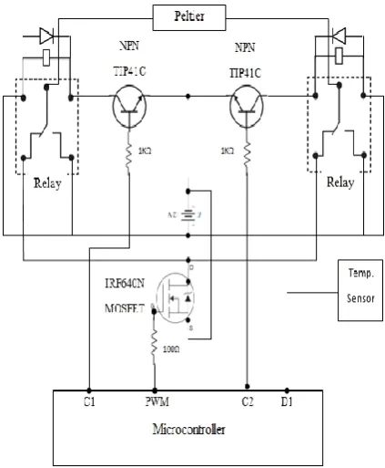
Figure 3 has been shown the proposed control circuit that controls on the current direction the pass through the Peltier. The direction of current will led to change the status of the Peltier either heating or cooling.
The upper part of this circuit, this part is works on reversing the voltage polarity on the terminals of the Peltier by using two mechanical relays. The lower part must be initialized due to regulate the applied voltage on the Peltier in order to satisfy the desired temperature.
The microcontroller could be employed in order to drive the operation of this circuit.
When C1 high and C2 low, the Peltier gives cold air.
When C1 low and C2 high, the Peltier gives warm air. The proposed circuit must be employed in order to dealing with the Peltier that operates on 12VDC, this circuit feeds the Peltier either +12VDC or -12VDC in order to run the Peltier for cooling or warming according the control signals that comes from Arduino 5V.
Finally, The Mosfet IRF640N has been included in the lower part to regulate the applied voltage across the Peltier terminal. A pulse width modulation (PWM) signal is initiated by the microcontroller to achieve the regulation process.
3.2
Software Design (Fuzzy Controller)
Fuzzy Inference Engine has been designed and implemented in order to manage and control the entire process. The fuzzy controller has two inputs (Err and ΔErr) and one output (PWM).
[image:3.595.315.548.159.358.2]The universe of discourse has been chosen for both inputs are (-10 ~ +10) and (-5 ~ +5) for Err and ΔErr respectively, The Err and ΔErr could be contained five triangle membership functions (NB, NS, Z, PS, PB). Figures (4 , 5) have been shown the membership functions of Err and ΔErr respectively.
Fig 4: Membership functions of Error.
Fig 5: Change of error membership function.
[image:3.595.56.279.316.507.2]The universe of discourse of the output is (-255 ~ +255). Also, the output should be divided into five linguistic variables as shown in Figure 6.
Fig 6: The membership functions of the fuzzy control system output.
Figure 6 has been shown the output membership Functions, the output’s sign can be positive or negative. This sign refer to specific status either cooling or heating. This process will lead to put the proper polarity on Peltier terminal, heating when the output was positive, and cooling when the fuzzy output was negative.
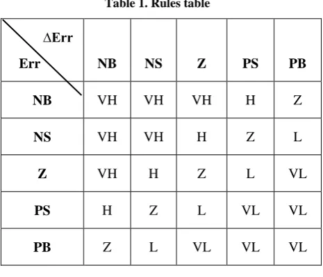
The rules should be written to force the system process the inputs according these rules that designed to ensure the
system works correctly. Table 1 has been depicted the rules for the implemented system.
Where:
NB: Negative Big, NS: Negative Small, Z: Zero, PS: Positive Big, PB: Positive Big, VH: Very High, H: High, VL: Very Low, L: Low.
Table 1. Rules table
∆Err
Err
NB
NS
Z
PS
PB
NB
VH
VH
VH
H
Z
NS
VH
VH
H
Z
L
Z
VH
H
Z
L
VL
PS
H
Z
L
VL
VL
PB
Z
L
VL
VL
VL
4.
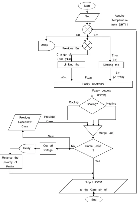
FLOW OF OPERATION
Figure 7 has been illustrated the flow chart of the entire system, the operations could be started with putting a specific set-point of temperature degree then calculate the Err and ΔErr, These values must be considered as inputs of fuzzy controller. Also, these inputs led the fuzzy controller to take a decision. The making decision process compromises identify the status that either cooling or heating, via (c1 and c2) and should select the amount of required PWM signal.
The control signals (C1 and C2) are employed to operate or not the relays. This process will lead to select the suitable voltage polarity that applied on Peltier terminals. Also, the PWM (output) could be used to regulate applied voltage by using Mosfet IRF640N.
At the moment of reverse the voltage polarity, the Peltier must be protected from any damage due to fast polarity changing. For that the delay is utilized until ensure that both Peltier's surfaces have the same temperature degree approximately.
5.
BTU CALCULATION FOR
COOLING/HEATING GREENHOUSE
STRUCTURE
The previous work has been implemented and tested in real world. The structure dimensions of the greenhouse prototype are: Length is 60 cm (1.9685 feet), the Width is 40 cm (1.31234 feet), and the height is 40 cm (1.31234 feet)[8].
𝐴𝑟𝑒𝑎 𝑜𝑓 𝑡𝑒 𝑔𝑟𝑒𝑒𝑛𝑜𝑢𝑠𝑒
= 𝑙𝑒𝑛𝑔𝑡 ∗ 𝑤𝑖𝑑𝑡 ∗ 𝑒𝑖𝑔𝑡
= 1.9685 ∗ 1.31234 ∗ 1.31234
= 3.3902221085186 𝑓𝑡3 (𝑐𝑢𝑏𝑖𝑐 𝑓𝑜𝑜𝑡𝑎𝑔𝑒)
[image:3.595.55.279.560.633.2]follow to calculate the Required British Thermal Unit (BTU) [8].
𝑇𝑒 𝐵𝑇𝑈 𝑛𝑒𝑒𝑑𝑒𝑑 = 3.4 ∗ 5
= 17 𝐵𝑇𝑈 (𝐵𝑟𝑖𝑡𝑖𝑠 𝑡𝑒𝑟𝑚𝑎𝑙 𝑢𝑛𝑖𝑡).
Then is important to know the greenhouse is poor insulation because the existence of large windows, rooms with many exterior walls will determine a higher requirement so increase your calculation by 10% - 20% according the rules of calculates the required BTU.
𝑇𝑒 𝐵𝑇𝑈 𝑛𝑒𝑒𝑑𝑒𝑑 = 17 ∗ 20% + 17 = 20.4 𝐵𝑇𝑈
Now, the desired temperature degree should be assumed for example 25C.
𝑇𝑒 𝑇𝑜𝑡𝑎𝑙 𝐵𝑇𝑈 = 20.4 ∗ 0.133 ∗ 25 = 67.83 𝐵𝑇𝑈
The thermo-electric cooler provide 260 BTU per hour approximately.
Time required for heating the greenhouse from Zero C till 25 C is could be calculated as follow:
= (68/260) ∗ 60
Change of Error (∆Err)
∆Err (-5 ~ 5)
Err (-10~10)
Fuzzy inputs
Fuzzy outputs (PWM)
Heating Cooling
Yes
Error (Err) Err
Previous Err
Previous Case
Merge unit
-
Err
-
+
+
[image:5.595.83.537.74.741.2]Fig 7: The flow chart of the temperature control algorithm Limiting the
∆Err
Limiting the Err
Fuzzy Controller
Cooling?
Previous Case=new
Case
New Case
Reverse the polarity of
Peltier
No Delay
Output PWM
to the Gate pin of IRF640N Delay
Same Case ? Cut off
voltage
Set point
Acquire Temperature from DHT11
Sensor Start
6.
RESULTS
In order to demonstrate the overall system results. A MatLab/Simulink has been designed for this purpose due to the shortage of microcontroller abilities in drawing graphs.
Figure 8 shows the Simulink structure to read the temperature from the sensor in order to be plotted as a graph.
Lm35 temperature sensor could be wired with the microcontroller, and then the MatLab/Simulink should be synchronized with the microcontroller in order to pass the information form the microcontroller toward the computer MatLab and vice versa.
The system has been tested with different initial and set value of temperature. Several experiments are starting with the high initial value and asked to reach a lower set point, while the others are starting with low initial values to reach a higher set point.
Figures (9 – 13) shows different system experiments that verify the system performance.
It is clear from these figures, that in all experiments the set point is captured in an acceptable time period.
It is important to know that this result from greenhouse prototype has a dimension 30 cm length and 20 cm width and height 20 cm. That because the response must be obvious like the Figures (9 – 13).
[image:6.595.317.544.184.318.2]At First, the system has been settled to 20° C and must provide knowledge of starting temperature degree without any effect is (25° ~ 28°) C. The Figure 9 illustrates the response of the system.
Fig 9: Set-point is 20°, initial value 27°, and the Response of the system
The starting temperature degree is more than 27° C and the desired temperature degree is 20° C. In order to satisfy the desired temperature degree, the system should be operated as cooling by putting the correct voltage polarity. Also, the PWM must be calculated by IRF640N to produce the correct amount of voltage on Peltier terminal.
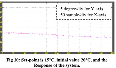
Then the system is settled to 15° C, the previous temperature is about 20°C. Figure 10 shows the response.
Fig 10: Set-point is 15°C, initial value 20°C, and the Response of the system.
This case could be considered as cooling too, then output PWM to produce the suitable voltage on Peltier.
[image:6.595.51.281.416.539.2]The third set point is 30° and the starting temperature is 28° C. Figure 11 will show the response of the system.
Fig 11: Set-point is 30°C, initial value 28°C, and the Response of the system.
Fig 8: MatLab/Simulink block diagram for drawing the system’s response
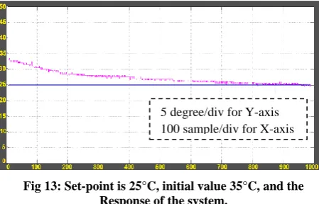
5 degree/div for Y-axis 100 sample/div for X-axis
5 degree/div for Y-axis 50 sample/div for X-axis
[image:6.595.73.525.579.734.2]This experiment is obviously heating case, it is important to note that the current case (cooling) is different from the previous case (heating), so that should follow this procedure:
1. Cut-off the voltage from delivering to Peltier.
2. Then should wait till the both sides of Peltier’s surfaces have the same temperature degree approximately.
3. Then put correct polarity on the Peltier terminal by producing the appropriate control signals that generated by the microcontroller.
4. Finally, the PWM to produce the suitable amount of voltage on the Peltier.
[image:7.595.56.282.272.411.2]The Fourth experiment compromising settled the system to 35°, and the temperature degree at the starting moment is about 30° C as shows in Figure 12:
Fig 12: Set-point is 35°C, initial value 30°C, and the Response of the system.
This experiment is a heating case which is the same previous case, so no reverse polarity required. The output (PWM) should be produced directly and establish the correct voltage polarity on the Peltier terminal.
The fifth experiment is about setting the system with 25° C. while, the current temperature is 35° C. Figure 13 illustrates the system’s response.
Fig 13: Set-point is 25°C, initial value 35°C, and the Response of the system.
This experiment is cooling case which is different from the previous case, so that the procedure should be followed. The procedure could be started with cutting the voltage off from delivering to the Peltier. and then wait until both sides of Peltier have the same temperature approximately, then out the correct polarity, and finally output the PWM to produce the correct amount of voltage.
7.
CONCLUSION
The resulting system is stable, low cost, low power consumption that because of the thermo-electric cooler, which is a very useful tool that has no mechanical parts and numerous advantages. The Peltier could be derived by a proposed electronic circuit that compromising a simple tools as transistors, relays, and diodes. This control circuit that has been implemented in order to control on the current directions, as a result the Peltier must be produced either heating or cooling in respect to control signals that generated by a fuzzy controller, which depend on two inputs, Err (the difference between the desired temperature and the actual temperature) and ΔErr (the difference between the current error and previous error). The Fuzzy controller has been resided completely inside microcontroller without require any external processing. This feature could be improved the system to be more practicality, robustness, and satisfy best performance. The system has been tested with different transition some tasting started with a low initial value and raises the temperature inside the greenhouse, and some experiments start with a high initial value and decrease the temperature inside the greenhouse. In general, the proposed system could be used to stabilize the desired temperature inside the greenhouse and that contributed to providing suitable circumstances for plants.
This system will be connected with practical IoT(Internet of Things) system in order to enable the peasants put their desired temperature degree inside the greenhouse prototype structure remotely. Also, enable the farmers to monitor the temperature inside the greenhouse from anywhere in this world with high performance and stable service.
8.
REFERENCES
[1] D. Chaudhary, S. Nayse, and L. Waghmare, "Application of wireless sensor networks for greenhouse parameter control in precision agriculture," International Journal of Wireless & Mobile Networks (IJWMN) Vol, vol. 3, pp. 140-149, 2011.
[2] M. D. Thakor, S. Hadia, and A. Kumar, "Precise temperature control through Thermoelectric Cooler with PID controller," in Communications and Signal Processing (ICCSP), 2015 International Conference on, 2015, pp. 1118-1122.
[3] S. Dai and Y. Li, "Applied Research of the Intelligent Temperature-Controlled Speed Adjustable Motor in Radiator Fan," in Intelligent System Design and Engineering Application (ISDEA), 2012 Second International Conference on, 2012, pp. 779-782.
[4] A. Montoya, J. Guzmán, F. Rodríguez, and J. Sánchez-Molina, "A hybrid-controlled approach for maintaining nocturnal greenhouse temperature: Simulation study," Computers and Electronics in Agriculture, vol. 123, pp. 116-124, 2016.
[5] S. Revathi and N. Sivakumaran, "Fuzzy Based Temperature Control of Greenhouse," IFAC-PapersOnLine, vol. 49, pp. 549-554, 2016.
[6] R.-O. Grigoriu, A. Voda, N. Arghira, V. Calofir, and S. S. Iliescu, "Temperature control of a greenhouse heated by renewable energy sources," in Electrical Machines & Power Electronics (ACEMP), 2015 Intl Conference on Optimization of Electrical & Electronic Equipment (OPTIM) & 2015 Intl Symposium on Advanced
Electromechanical Motion Systems
5 degree/div for Y-axis 50 sample/div for X-axis
[image:7.595.56.281.505.649.2](ELECTROMOTION), 2015 Intl Aegean Conference on, 2015, pp. 494-499.
[7] S. Twaha, J. Zhu, Y. Yan, and B. Li, "A comprehensive review of thermoelectric technology: Materials, applications, modelling and performance improvement," Renewable and Sustainable Energy Reviews, vol. 65, pp. 698-726, 2016.