© 2019, IRJET | Impact Factor value: 7.211 | ISO 9001:2008 Certified Journal | Page 3958
SMART STREET LIGHTING BASED ON PULSE WIDTH MODULATION
Dr. Babu Paul
1, Anupama R
2, Muhammad Jasir P
3, Sangeeth P Karun
4, Santo Shaju
51
Professor, Dept. of Electrical and Electronics Engineering, Mar Athanasius College of Engineering,
Kothamangalam, Kerala, India
2,3,4,5
Under Graduate Students, Mar
Athanasius College of Engineering, Kothamangalam, Kerala, India
---***---Abstract -
Solar powered street lighting systems provide clear visibility for pedestrians and drivers, without need of AC grid access. These reliable street lights quickly pay back the low initial investment with substantial energy savings. But a more efficient design is required for attaining a complete productivity and reliability of the system. For this improvement in two domains are necessary, that is in voltage conversion level and in the lighting module. Conventional DC-DC converter is re-designed to a Switched Capacitor based dual switch high boost converter that has a higher efficiency and power density. A smart LED based lighting module is used for illumination that has automatic intensity control based on ambient light and vehicle movement. Pulse width modulation technique is used for controlling the power input to street light by controlling the converter driving signal, so the system become energy efficient. Pulse width is controlled by an LDR sensor and an IR sensor. LDR sensor is used for switching ON and OFF the lights according to the ambient light intensity. LDR sensor is used for changing the brightness level when presence or absence of vehicles are detected. That is converter Produces a minimum power when no vehicles are detected, and a maximum power when vehicle is detected. Converter used is of switched capacitor based which requires a comparatively lesser duty cycle, so switching stress in MOSFETs are less which eventually increases the life of system.Key Words:Switched capacitor based dual switch high-boost DC-DC converter, Automatic intensity control, LDR Sensor, IR Sensor, Pulse Width Modulation, Energy efficient.
1. INTRODUCTION
Due to increasing concerns about global warming and climate change, renewable energy sources like wind and solar are receiving greater attention from researchers world-wide. Solar PV is an excellent source of energy available all over the globe but in DC form. If it can be utilized without converting this to AC, it can be really energy efficient. LEDs for lighting purposes have become extremely popular lately due to their higher lumens yield with less wattage consumption; also
,
they work on DC. So, Solar PV-LED is an ideal combination for outdoor lighting.Even in daytime when there is no requirement of street lights, it is frequently seen that these lights remain ON violating the energy conservation rule. This continuous
lighting pollutes the environment as well as increases the tariff of the electricity.
The combination of a solar PV supplying power to a street light equipped with LEDs with automatic intensity control through a DC-DC converter is explored in this. The main part is the boost converter. A switched-capacitor (SC)-based dual-switch dc-dc converter with a high-boost voltage gain is proposed in this paper. The proposed converter can obtain a high-voltage gain with a small duty cycle, which decreases the voltage stress and the conduction loss on the power switches.
An automatic intensity controller which acts according to the presence of vehicles is the important part of our street lighting system. IR sensor is used for the detection. Pulse width modulation technique is used for varying intensity levels. So no energy is lost in the process. The switching ON and OFF of the street light is automated using an ambient light sensor. So no manual intervention is needed and no energy loss will occur due to human error. LDR based sensor is used in the system.
Basic block diagram of the system is given below:
Fig-1: Block Diagram
© 2019, IRJET | Impact Factor value: 7.211 | ISO 9001:2008 Certified Journal | Page 3959 levels. The system is efficient because unwanted use of
power is minimized using Pulse Width Modulation Technology in the absence of vehicles.
The main components used are: • Solar PV array
• Storage Battery • Boost Converter • Power LED Array • Sensors
• Microcontroller
1.1 Solar PV array
A solar PV module is designed using a number of series connected solar cells. Each solar cell has an open circuit voltage (Voc) of 0.5V and a short circuit current (Isc) of 5.12A. A Maximum power (Pmpp) occurs generally at 85 percent of Voc (Vmpp) and 85 percent of Isc (Impp). Thus Impp is 4.35A and Vmpp is 0.425V for each cell. A group of 40 cells connected in series can obtain a maximum voltage of 17V.
Fig-2: Equivalent circuit of PV module
1.2 Storage Battery
Battery plays an important role in solar street lighting system, to provide energy during night time. The Li-ion battery, a generic parameterized battery model, which is available in Matlab-Simulink can be considered for this proposed system. The battery should have enough charge storage for supplying the street lights for a minimum of 2 days.
1.3 Boost Converter
This is the most important part of this system. A switched-capacitor (SC)-based dual-switch dc-dc converter with a high-boost voltage gain is proposed in this paper. The proposed converter can obtain a high-voltage gain with a small duty cycle, which decreases the voltage stress and the conduction loss on the power switches. The circuit is shown below. There are two modes of operation which will be discussed later.
Fig-3: Switched Capacitor based Dual-switch converter
1.4 Power LED Array
The LED characteristics are similar to conventional PN junction. The I-V characteristic of an LED is shown below. The number of power LEDs used is calculated as per the light requirement. The converter is operated in such a way that LEDs should operate in full intensity till midnight. As the reference value changes the intensity of the power LED also changes. As per the datasheet the 100% luminous flux is produced at a forward current of 350mA per LED. In this proposed system, a considerable amount of power can be saved by having intensity control.
Fig-4: I-V characteristics of an LED
1.5 Sensors and Microcontroller
© 2019, IRJET | Impact Factor value: 7.211 | ISO 9001:2008 Certified Journal | Page 3960
2.
SWITCHED CAPACITOR BASED DC-DC
CONVERTER
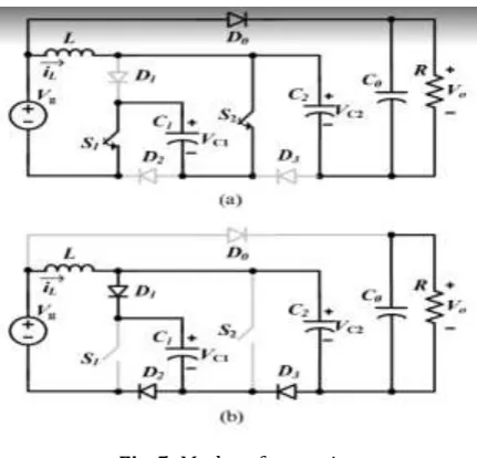
Figure shows the proposed SC-based dual-switch (SCDS) converter with the high voltage gain. It consists of one inductor (L), three capacitors (C0-C2), four power diodes (D0-D3), two power switches (S1 and S2), and a resistive load (R).Key waveforms of the proposed SCDS converter operating in the CCM is also shown. Both switches, S1 and S2, are turned on and off simultaneously. To simplify the circuit analyses of the proposed converter in the CCM , the following assumptions were made: 1) All devices are ideal and lossless; 2) the capacitance of the capacitors is large enough to maintain the constant capacitor voltage; and 3) the current flow to the inductor increases or decreases linearly.
Fig-5: Modes of operation
Fig-5 shows the modes of operation of the converter. Mode 1: S1 and S2 are turned ON. The inductor is charged while the C1 and C2 capacitors are discharged. The D0 diode is forward-biased, while the D1, D2, and D3 diodes are reverse-biased. The time interval in this mode is DT, where D and T are the duty cycle and the switching period, respectively. By applying Kirchhoff’s Voltage Law (KVL) in Fig. 5 (a), the following formula is derived:
(1)
(2)
Mode 2: S1 and S2 are switched OFF; the D1, D2, and D3 diodes are forward-biased while the D0 diode is reverse-biased. The time interval in this mode is (1D)T. During this mode, the inductor L is discharged while the C1 and C2 capacitors are charged, and the following formula is derived:
(3)
(4)
(5)
By substituting (5) into (2), the output-voltage gain of the proposed SCDS converter in the CCM is as follows:
(6)
3. SIMULATION OF SCDS CONVERTER WITH
RESULTS
Open loop simulations with two duty cycles were realised. The input voltage is 24 V and it is boosted to 75 V and 120 V. Design of converter is as follows:
3.1 Inductor selection
The peak-to-peak inductor current ΔIL is calculated. Assuming that ∆IL=ri%IL, the required inductance should be as follows:
(7)
3.2 Capacitor Selection
Capacitors are designed according to the capacitor-voltage ripple. The current flow to the C1 capacitor in mode 1 of the proposed converter equals the peak current of the switch S1, while the current flow to the C2 capacitor equals the peak current of the diode.
(8)
(9)
To limit the ripple on the output voltage using the rv%, the C0 capacitance should be as follows:
[image:3.595.53.269.279.486.2]© 2019, IRJET | Impact Factor value: 7.211 | ISO 9001:2008 Certified Journal | Page 3961
3.3 Simulink model of SCDS converter
Case 1: Duty cycle =12%
Fig-6: Simulink model with 75V output
Result 1: From the graph that the output value obtained is nearly 75V. So when realizing in hardware this is the case when minimum intensity is obtained. If the IR does not detect any obstacles this case will be activated.
Fig-7: Output 1(75V)
Case 2: Duty cycle =48%
Fig-8: Simulink model with 120V
Result 2:The output value obtained is nearly 120V . When
realising in hardware this is the case when maximum intensity is obtained. If the IR detect any obstacles this case will be activated.
© 2019, IRJET | Impact Factor value: 7.211 | ISO 9001:2008 Certified Journal | Page 3962
4. PROGRAM ALGORITHM
The microprocessor continuously checks the IR sensor signal values. When a signal is received a corresponding decision is selected. Here it is switching the duty cycle which is to be fed to the converter. In effect the driving of converter is controlled by IR sensor.
Program algorithm of automatic intensity controller is shown below.
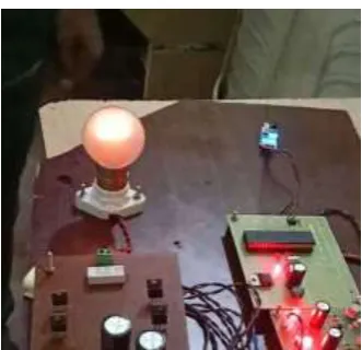
[image:5.595.69.262.244.432.2]5. PROTOTYPE
Figure 10 shows the working model of the system. Starting with the transformers for powering various components of the system. A 230V/24V 1A transformer powers the SCDS converter and 230V/12V 0.5A transformer powers the controller and the driver boards.
Fig-10: Hardware
The full wave bridge rectifier marked as 1 in the Fig: 10 is for converting 24 V AC from supply transformer to 24 V DC
powering the converter marked as 2. Position 3 is the single phase inverter for converting output to AC voltage for supplying the filament lamp marked 5. The relay (4) act as the switch which is controlled by IR sensor (7). The driver board (9) drives the MOSFET in both converter and inverter. The pulses are generated by the microcontroller (8) which is further controlled by LDR sensor marked 6.
6. RESULT
The MOSFET driving pulses from the output of driver circuit were examined using a Digital Storage Oscilloscope. The corresponding state of bulb is also verified.
6.1 In the absence of obstacles
[image:5.595.322.549.384.522.2]It is clear that the pulses are exactly of 15 V amplitude for driving the MOSFET. In this case IR signals are absent, that is no obstacles are detected. So the microcontroller will select the duty cycle as 12 %. The output voltage thus obtained is 75 V, and so the bulb is glowing with minimum intensity.
Fig-11: PWM when IR signals are off
[image:5.595.37.287.549.703.2] [image:5.595.351.517.554.714.2]© 2019, IRJET | Impact Factor value: 7.211 | ISO 9001:2008 Certified Journal | Page 3963 • Duty cycle = 12 %
• Obtained output = 75 V
• Bulb glows in minimum intensity
6.2 In the presence of obstacles
Here also we are getting 15 V in driving pulses. In this case the IR sensor detect vehicle and a signal is sent to the mico-controller. Then it selects the duty cycle as 48 %. We get nearly 120 V in the output. So the bulb glows in maximum intensity.
Fig-13: PWM when IR signals are on
Fig-14: Bulb glows in maximum intensity • Duty cycle = 48 %
• Obtained output = 120 V
• Bulb glows in maximum intensity
7. CONCLUSION
Street lights are a highly energy consuming sector in every society. Due to the need for supplying power continously for almost half a day, a better lighting scheme is to designed. A solar PV based street lighting system with automatic intensity control can effect a power saving of up to 50 percent during traffic-free hours of the road. The battery charging is done during the day time via a solar PV controller. The proposed SCDS converter have a simple structure, thereby achieving a high-voltage gain with asmall duty cycle for the reduction of the conduction loss of the power switches, and a low-voltage stress on the MOSFETs and diodes. Also, an overall comparison between the proposed converter and other non-isolated dc-dc converters is addressed. Being an automated system, the man-made problems regarding switching off the lights are overcome here. The simulation and experiment results are demonstrated to verify the theoretical analysis. The automatic intensity controller of light is also beneficial for the drivers as manual headlight switching is no longer needed. A better street lighting system using switched capacitor based dual switch DC-DC converter was studied and demonstrated using a prototype.
REFERENCES
[1] “LED Based Street Lighting with Automatic Control
Using Solar PV” 205 IEEE IAS Joint Industrial And Commercial Power Systems/ Petroleum Ans Chemical Industry Conference (ICPSPCIC) by Deepu Vijay M, Kamlesh Shah, G.Bhuvaneswari and Bhim Singh.
[2] “Switched-Capacitor-Based Dual-Switch High-Boost
DC-DC Converter” IEEE, Transactions on Power electronics by Minh-Khai Nguyen, 2017.
[3] “A Smart Street-Light Intensity Optmiser” by Bilam Roy,
Aditya Acharya, Tanmoy K Roy, Sudip Kuila, Jayita Datta.
[4] Alonso, J.M.; Gacio, D.; Sichirollo, F.; Seidel, A.R.; Dalla
Costa, M.A., “Modeling single-stage high-power-factor AC-DC converters for LED driving applications,” Industry Applications Society Annual Meeting 2013 IEEE , vol., no., pp.1,8, 6-11 Oct. 2013.
[5] F. L. Tofoli, D. C. Pereira, W. J. Paula, and D. S. O. Junior,
Survey on nonisolated high-voltage step-up dcdc topologies based on the boost converter, IET Power Electron., vol. 8, no. 10, pp. 20442057, Oct. 2015.
[6] Akshay Balachandran, Murali Siva, V.
Parthasarathi,Surya and Shriram K. Vasudevan, An Innovation in the Field of Street Lighting System with Cost and Energy Efficiency, Indian Journal of Science and
Technology, Vol 8(17), DOI:
10.17485/ijst/2015/v8i17/61261, August 2015.
[7] W. Li, and X. He, Review of nonisolated high-step-up