Score Evaluation of MRI Sequence Type Related Artifacts
after Interbody Fusion with Metallic Implants—A Spine
Specimen Study
Thorsten Ernstberger1*, Gottfried Buchhorn2, Gabert Heidrich3 1
Clinic for Spinal Surgery, Klinikum Bad Bramstedt, Bad Bramstedt, Germany 2
Biomaterial Laboratory, Department of Orthopaedic Surgery, University of Göttingen, Göttingen, Germany 3
Center of Radiology Weilheim, Ambulatory Healthcare Center, Weilheim i. Obb, Germany Email: *[email protected]
Received February 1, 2012; revised March 16, 2012; accepted April 20, 2012
ABSTRACT
Introduction: According to anterior spine fusion intervertebral disc spacers made of titanium or cobalt-chromium al-loys are of special interest. With regard to postoperative problems implant related artifacts can lead to a decreased MRI evaluation. The focus of this study was to compare the respective implant artifact range dependend on different MRI sequences. To simplify artifact evaluation we introduced in this study a new developed 0-1-2 score. Material and Methods: We performed an MRI artifact evaluation of 2 different metallic intervertebral disc spacers (cobalt-chromium- and titanium alloy). A carcass porcine spine was employed. Considering 12 defined spinal regions of interest we evalu-ated the respective implant artifact properties independent from the total artifact volume by using a new developed 0-1-2 score. The artifact range was documented for 15 different MRI-sequences. Results: For the titanium spacer as well as the cobalt-chromium-spacer an MRI evaluation of the implant/disc space situation could not be carried out. In contrast to the cobalt chromium spacer the titanium spacer allowed a good differentiation of the spinal canal opposite to the implant. Optimal MRI imaging results for both metallic intervertebral disc spacers could be achieved considering TSE sequences. Conclusion: A comparison of these two metallic spacers showed in all examined sequences clear ad-vantages in favour of the titanium spacer. The best MRI representation of both tested implants by reducing implant re-lated artifacts could be achieved with fast spin echo (TSE) sequences. In spite of the use of TSE sequences a variability of susceptibility artifacts has to be included with regard to implant shape and material. With regard to the results of this study the easy use of a new developed artifact score represented a useful help to compare implant related MRI artifact properties independent from the actual implant related total artifact volume.
Keywords: Metallic Intervertebral Disc Spacer; Artifact Score; MRI; Susceptibility Artifacts
1. Introduction
Regarding to spine diseases the magnetic resonance im-aging is considered as a standard procedure for preopera-tive diagnostic. Especially disc pathologies as well as changes of the spinal canal can be represented with high precision.
According to anterior spine fusion different interverte-bral disc spacers are of special interest. The implant de-sign is dependent on the respective material as well as implantation characteristics. Considering postoperative complications after lumbar vertebra fusion magnetic resonance imaging can be necessary. In this context im-plant related artifacts can lead to a decreased evaluation of the MRI scan. Recent studies have shown that artifact disturbances particularly with metallic implants can be
minimized by modifications of routine MRI sequences [1]. On account of such experiences the present cadaveric study should demonstrate, to what extent implant related MRI artifacts can affect an evaluation of intervertebral disc spacers under special consideration to neighbouring structures. For easy evaluation of implant related artefact dimensions, we conducted a new score, which was de-veloped on the basis of defined anatomical regions of interest. In this context the susceptibility artifacts of 2 different metallic intervertebral disc spacers was docu-mented for 15 MRI sequences and possible implant re-lated factors were discussed.
2. Material and Methods
In this study we performed a magnetic resonance imag-ing evaluation of 2 implanted metallic intervertebral disc
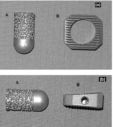
spacers which differed in form, material, surface qualities and implantation characteristics (Figures 1(a) and (b)). We employed the spine of a slaughted pig. After prepara-tion the paravertebral muscles including the surrounding skin as well as the psoas muscles were kept. Special at-tention was applied to the maintenance of the neurological structures of the spinal canal. Anatomically the pig mye-lon reaches up to the vertebra S 2, therefore, were con-sidered the distal third of the thoracic spine as well as the whole lumbar spine. To estimate the maximally possible artifact extension, we carried out a first MRI evaluation with a cobalt-chromium intervertebral disc spacer con-sidering its ferromagnetic material properties. This spacer was completely surrounded with a homogeneous coat of meat. Regarding to different MRI-sequences a maximum artifact width of 6.5 cm could be calculated. Considering this result we determined the implantation distances of both metallic disc spacers.
2.1. Implants
Intervertebral disc dowel (IDD: ESKA Implants GmbH & Co, Lübeck, Germany, Figures 1(a) and (b-A).
Material: Cobalt-chromium-molybdenum.
This metallic implant demonstrates a cylindric, slightly conical bullet shape. The implant length was 35 mm, the diameter amounted to 15 mm. On the one side this im-plant demonstrates a rounded cap. The imim-plant surface has a patended metallic structure. This surface configure-
Figure 1. Implants. A: Intervertebral disc dowel (Cobalt- chromium-molybdenum) on top + lateral view; B: IBS-spacer (Titanium-aluminium-vanadium) on top + lateral view.
tion shows similarities to spongy bone.
Intervertebral Body Spacer (IBS LIBERTY: Peter Brehm Company, Weisendorf, Germany: Figures 1(a) and
(b-B).
Material: Titanium-aluminium-vanadium
Considering an implant height of 10 mm the IBS spacer has a square shape of 25 × 25 mm with a dorsal slope of 7 degrees of the upper surface in anteroposterior direction.
The implant surfaces demonstrates a tooth ribs con-figuration. In addition, this implant represents a central drilling of 15 mm for a possible spongiosa accomodation.
2.2. Implantation
In accordance to human the spinal column of the porcine specimen shows a vertebral size increase in craniocaudal direction. In this connection the lower lumbar vertebrae represents a maximum size of 25 × 25 × 20 mm (height × width × depth).
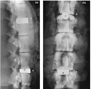
The examined implants showed an oversizing in con-trast to the respective intervertebral disc space. In this context we included an implant extension into the spinal canal. The preparation of the lumbar and thoracic disc spaces were performed considering a possible central positioning of the examined implants. The paravertebral muscles including the skin as well as the psoas muscles were left. After intervertebral disc removing the respec-tive intervertebral disc spacers were implanted. The maximally implantation depth was reached if the implant stand in line to the anterior vertebra front. Finally a con-ventional radiograph documentation was carried out (Figures 2(a) and (b)). After a first MRI test run an ante-rior supplementary meat coat was necessary for a suffi-cient referencing of the used implants.
2.3. Magnetic Resonance Imaging
[image:2.595.59.288.438.696.2]All examinations were executed with a 1.5T-MRI (Mag-netom-Symphony, Siemens AG. Medical Solution, Er-langen, Germany). Dependent on the respective MRI- sequence we selected a matrix with 256 × 256, 384 × 384 or 512 × 512 combined with a Field of View (FOV) of 500 mms. With the exception of the T1 FLASH 2D se-quence (slice thickness 5.5 mm) and the T2 DESS 3D sequence (slice thickness 1.5 mm) all other MRI se-quences were performed with a slice thickness of 3 mm. The examination record with all parameters are listed in
Table 1. Beneath T1 spin echo (SE) and fast spin echo (TSE) sequences this protocoll also contained protone densitiy (PD) sequences as well as 2-D and 3-D se-quences.
2.4. Evaluation Unity
Table 1. MRI-sequence record.
Sequences FA TR TE ST BW FOV Number of slices Matrix
T1 FLASH 2D 70 181 4,8 5.5 260 500 19 256 × 256
T1 FLASH 2D FS 70 275 4,76 5.5 260 500 19 256 × 256
T2 MEDIC 2D FS 40 2660 27 3.0 70 500 40 256 × 256
T1 FLASH 3D 60 60 11 3.0 70 500 40 256 × 256
T2 DESS 3D 25 23.68 6.63 1.5 130 500 64 256 × 256
TOF FISP 3D 25 36 4.59 3.0 130 500 32 384 × 384
T2 CISS 3D 70 10.16 5.08 3.0 130 500 64 256 × 256
T1 TSE 150 2260 14 3.0 150 500 40 512 × 512
T1 TSE var 150 600 14 3.0 150 500 40 512 × 512
T1 SE 90 1270 14 3.0 90 500 40 512 × 512
T1 SE var 90 600 14 3.0 90 500 40 512 × 512
T1 SE FS var 90 684 14 3.0 90 500 40 512 × 512
T2 TSE/PD 150 6110 14 3.0 130 500 40 256 × 256
T2 TSE/PD FS 150 6760 14 3.0 130 500 40 256 × 256
STIR 180 10000 38 3.0 130 500 40 256 × 256
FLASH = Fast Low Angle Shot; MEDIC = Multi Echo Data Image Combination; DESS = Dual Echoe Steady State; FS = Fat Saturated; FISP = Fast Imaging with Steady Precession; CISS = Constructive Interference in Stady State; SE = Spin Echo; TSE = Turbo Spin Echo; PD = Protone densitiy; STIR = Short Tau Inversion Recovery; TOF = Time of Flight; TR = Time of Repitition; TE = Time of Echo; FA = Flip Angle; ST = Slab Thickness; BW = Band Width; FOV = Field Of View; var = varied.
Figure 2. Conventional radiograph. A: Intervertebral disc dowel (lateral + coronal view); B: IBS-spacer (lateral + coronal iew).
v
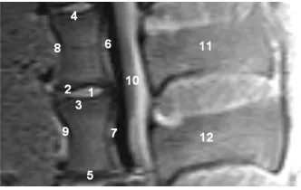
[image:3.595.140.457.401.708.2]scans. An evaluation unit was defined as 2 adjacent ver-tebrae encompassing the intervertebral disc space. 12 regions of interest (ROI) were demarcated (Figure 3). Every ROI could achieve a maximum score of 2 points. A total score of 24 points was equivalent to a score of 100%. Two board-certified specialists (one radiologist (GH) and one spinal surgeon (TE)) experienced in read-ing spinal MRI evaluated the scans independently of each other. The evaluators scored regions as 0 = not dis-tinguishable, 1 = partly distinguishable and 2 = com-pletely distinguishable. The interobserver validation of the scoring system across all 15 sequences was tested for statistical significance using a t test with a significance level of P = 0.05 (Tables 2 and 3).
3. Results
On the basis of 15 different MRI sequences an imaging scoring were performed considering implant related MRI artifacts (Figures 4(a)-(d)). A total score of maximally 24 points could be achieved. Per MRI sequence the achieved score for every region of interest were added. Dependent on the respective intervertebral disc spacers it should be demontstrated which MRI sequences guarantee an optimal implant imaging.
3.1. Intervertebral Disc Dowel (IDD)
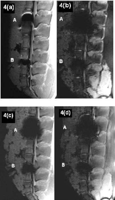
According to the T1 TSE sequences (Figure 4(a-A)) the IDD could achieve a maximum total score of 17 points (Table 2). With regard to the relevant MRI scan the im-plant related susceptibility artifact could be clearly dif-ferentiated opposite the spinal surrounding. However, the determined regions of interest demonstrated a reduced MRI imaging quality of less than 50% (1 point). Only a limited evaluation of the implant-bone contact area was possible considering the artifact extension. Exclusively the distant vertebral end plates, anterior edge of the lower
[image:4.595.311.536.113.487.2]1. Intervertebral disc space; 2. Cranial adjacent plate; 3. Caudal adjacent plate; 4. Cranial distant plate; 5. Caudal distant plate; 6. Posterior edge of the cranial vertebra; 7. Posterior edge of the caudal vertebra; 8. Anterior edge of the cranial vertebra; 9. Anterior edge of the caudal verte-bra; 10. Spinal canal; 11. Cranial spinous process; 12. Caudal spinous process.
Figure 3. MRI-evaluation unity with regions of interest (porcine carcass spine).
Table 2. Total score values considering different MRI- sequences (1 = Spinal surgeon, 2 = Radiologist).
IBS IDD
MRI Sequence
1 2 1 2
T1 FLASH 2D
TR:181 TE:4 13 13 9 8
T1 FLASH 2D FS
TR:275 TE:4 13 13 10 10
T2 MEDIC 2D FS
TR:2660 TE:27 11 11 4 4
T1 FLASH 3D FS
TR:60 TE:11 10 10 5 6
T2 DESS 3D
TR:23 TE:6 13 12 6 6
T2 CISS 3D
TR:10 TE:5 13 12 7 7
T1 SE
TR:1270 TE:14 13 14 12 12
T1 TSE
TR:2260TE:14 15 15 12 12
T1 TSE
TR:600 TE:14 15 15 12 12
T1 SE
TR:600 TE:14 13 13 12 12
T1 SE FS
TR:684 TE:14 13 13 8 7
PD + T2 TSE
TR:6110 TE:14 13 13 8 8
PD + T2 TSE FS
TR:6760 TE:14 13 13 7 7
STIR
TR:10000 TE:38 13 13 10 10
TOF FISP 3D
[image:4.595.309.537.513.590.2]TR:36 TE:4 12 12 3 4
Table 3. Interobserver validation across all 15 sequences.
Mean score value Standard deviation
Spinal
surgeon Radiologist
Spinal
surgeon Radiologist
P value
IBS 12.87 12.8 +1.25 +1.32 P = 0.58
IDD 8.33 8.33 +3.02 +2.85 P = 1.0
[image:4.595.87.253.542.647.2](a) T1 TSE (TR: 2260, TE: 14); (b) T2 DESS 3D (TR: 23, TE: 6); (c) T1 FLASH 3D FS (TR: 60, TE: 11); (d) TOF FISP 3D (TR: 36, TE: 4).
Figure 4.(a)-(d) Artifact range considering different MRI- sequences. A: Cobalt-chromium-intervertebral disc dowel; B: IBS-titanium-spacer.
3.2. Intervertebral Body Spacer (IBS LIBERTY)
On account to T1 TSE, SE and T2 3D Sequences (Table 2) the IBS spacer could achieve a maximum score of 22 points respectively. With regard to the T1 SE and TSE sequences the susceptilibity artifact border could be clearly differentiated opposite the spinal surrounding. The regions of interest could be mainly represented to more than 50%. On the other hand only a limited evalua-tion of the implant-bone contact area was possible con-sidering the artifact extension. With regard to a differen-tiation of the spinal canal opposite the implant appropri-ate stappropri-atements could be done. The achieved MRI image quality does not allow any concrete statements about the real implant position. The lowest MRI imaging quality with a maximum score of 15 points could be demon-strated considering T1 FLASH 3D FS sequence (Figure 4(d-B)). The existing susceptilibity artifacts guarantee an unsufficiently evaluation of the implant surrounding
only.
3.3. Summarizing Evaluation
Independent on specific implant characteristics the best MRI imaging results for both metallic intervertebral disc spacers could be achieved considering fast spin echo sequences. A comparison of both metallic intervertebral disc spacers showed in all examined sequences clearly advantages in favour of the IBS titanium spacer. With regard to the favored fast spin echo sequences (T1 TSE) the IBS titanium pacer reached a total score of 15 points towards 12 points with the cobalt chromium interverte-bral disc dowel.
4. Discussion
With regard to the MRI diagnostic of spinal changes dif-ferent imaging sequences are available. In this context as a problem of special importance postoperative changes are to be considered after instrumented spine fusions. According to implant related artifacts an MRI imaging evaluation can be difficult. On account of documented disadvantages of bone grafts different intervertebral spacers are obtainable to supplement anterior spinal fu-sion [2-4]. In this context titanium alloys as well cobalt chromium alloys are of special interest. In contrast to bone grafting intervertebral disc spacer guarantee imme-diate load transmission with direct primary stability. De-pendent on the amount of susceptibility artifacts an MRI based evaluation of the respective implant situation can be executed. A local magnetic field gradient results in the area between two different structures with varying sus-ceptibility. In these sections the respective spins gyrate with different frequencies with the consequence of im-aging distortions [3-7]. According to this a great suscep-tibility difference resulted in a limited imaging evalua-tion.
Regarding to material related implant charcteristics the following aspects are of special meaning in MRI imag-ing:
1) Evaluation of implant form and position;
2) Implant differentiation opposite anatomically neigh- bouring structures.
[image:5.595.72.274.84.434.2]as well as the cobalt chromium disc dowel are to be un-derstood on the basis of increased susceptibility artifacts. Following the study results of Rudisch et al. [15] as well as Thomsen et al. [16] a lower artifact range could be noticed for titanium spacer in contrast to the cobalt chrome disc dowel. The best MRI imaging results of both metallic spacer could be achieved by using T1 TSE sequences. Additionally comparable results could be re-produced for the titanium spacer considering T1 SE and T2 CISS 3D sequences. Other MRI sequences according to the examination record demonstrated no further ad-vantages. Studies with regard to metallic artifacts in the anterior spine were performed by Vaccaro et al. [17] and Wang et al. [13] so far. Vaccaro et al. [17] examined in a human carcass study the MRI artifact rates of different metal particles which were brought in defined interverte-brale drillings and subsequently parafin beded. On ac-count of a lower particle density in contrast to clinical used metal implants Vacarro could not diagnosed any significant artifacts on account to T1 or T2 SE sequences. With regard to the metallic artifacts appeared in gradient echo-sequences a connection could be proved between the artifact size and the nickel content of the examined alloys. In this connection, an increasing nickel content effects a reduced susceptibility artifact expression.
Wang et al. [14] described in another carcass artifact study the MRI behavior of an intervertebral disc spacer made of titanium and tantalum. According to a correct implant position by using T1 SE sequences implant re-lated artifacts of the titanium spacer could be limited to the direct implant surrounding. The anatomically repre-sentation of neighbouring structures under special con-sideration of the spinal canal could be achieved without any problems. With regard to equally MRI sequences the diagnosed metallic artifacts of the titanium spacer as well as the cobalt-chromium disc dowel in our study must be discussed controversially. Considering both metallic spac-ers by using spin echo—as well as fast spin echo se-quences neither an evaluation of the implant form nor the implant position could be carried out certainly. Regard-ing to a phantom study of Rudisch et al. a relation be-tween the range of metallic artifacts and implant related characteristics like material, form and position could be demonstrated beneath the selected MRI sequence. In this connection already published results of similar artifact studies seem to be dependent on the respective study concept. In spite of the use of comparable MRI-sequences considering the MRI imaging of metallic spine implants a variability of the amount of susceptibility artifacts has to be included.
5. Conclusion
According to anterior spine fusion available metallic in-tervertebral disc spacers made of titanium or cobalt-
chrome alloys are of special interest. In spite of the use of favored fast spin echo MRI sequences a variability of the amount of susceptibility artifacts has to be included con-sidering the MRI imaging of metallic spine implants. Taking into account already documented studies beneath the chosen MRI sequence the artifact size seems to be affected by the implant shape as well as the implant ma-terial. Regarding our study results the easy use of a new developed artefact score demonstrated a useful help to compare implant related MRI artifact properties inde-pendent from the actual implant related total artifact volume.
REFERENCES
[1] T. Herold, W. C. Caro, G. Heers, L. Perlick, J. Grifka, S. Feuerbach, W. Nitz and M. Lenhart, “Influence of Se-quence Type on the Extent of the Susceptility Artifact in MRI—A Shoulder Specimen Study after Suture Anchor Repair,” Rofo, Vol. 176, No. 9, 2004, pp. 1296-1301. doi:10.1055/s-2004-813404
[2] J. W. Brantigan and A. D. Steffee, “A Carbon Fiber Im-plant to Aid Interbody Lumbar Fusion. Two-Year Clini-cal Results in the First 26 Patients,” Spine, Vol. 18, No. 14, 1993, pp. 2106-2107.
doi:10.1097/00007632-199310001-00030
[3] J. A. Goulet, L. E. Senunas, G. L. DeSilva and M. L. Greenfield, “Autogenous Iliac Crest Bone Graft: Com-plications and Functional Assessment,” Clinical Ortho-paedics & Related Research, Vol. 339, No. 339, 1997, pp. 76-81.
[4] B. N. Summers and S. M. Eisenstein, “Donor Site Pain from the Ilium. A Complication of Lumbar Spine Fusion,”
The Journal of Bone & Joint Surgery, Vol. 71, No. 4, 1989, pp. 677-680.
[5] C. Fellner, M. Behr, F. Fellner, P. Held, G. Handel and S. Feuerbach, “Artifacts in MR Imaging of the Temporo-mandibular Joint Caused by Dental Alloys: A Phantom Model Study at T1.5,” Rofo, Vol. 166, No. 5, 1997, pp. 421-428. doi:10.1055/s-2007-1015452
[6] S. Fritzsche, R. Thull and A. Haase, “Reduction of Arti-facts in Magnetic Resonance Images by Using Optimized Materials for Diagnostic Devices and Implants,” Biomed Tech (Berl), Vol. 3, No. 39, 1994, pp. 42-46.
[7] J. F. Schenck, “The Role of Magnetic Susceptibility in Magnetic Resonance Imaging: MRI Magnetic Compati-bility of the First and Second Kinds,” Medical Physics, Vol. 23, No. 6, 1996, pp. 815-850. doi:10.1118/1.597854 [8] C. B. Henk, W. Brodner, S. Grampp, M. Breitenseher, M.
Thurnher, G. H. Mostbeck and H. Imhof, “The Postop-erative Spine,” Top Magn Reson Imaging, Vol. 10, No. 4, 1999, pp. 247-64.
doi:10.1097/00002142-199908000-00006
[10] O. Ortiz, T. G. Pait, P. McAllister and K. Sauter, “Post-operative Magnetic Resonance Imaging with Titanium Implants of the Thoracic and Lumbar Spine,” Neurosur-gery, Vol. 38, No. 4, 1996, pp. 741-745.
[11] C. A. Petersilge, J. S. Lewin, J. L. Duerk, J. U. Yoo and A. J. Ghaneyem, “Optimizing Imaging Parameters for MR Evaluation of the Spine with Titanium Pedicle Screws,”
American Journal of Roentgenology, Vol. 166, No. 5, 1996, pp. 1213-1218.
[12] R. Rupp, N. A. Ebraheim, E. R. Savolaine and W. T. Jackson, “Magnetic Resonance Imaging Evaluation of the Spine with Metal Implants: General Safety and Superior Imaging with Titanium,” Spine, Vol. 18, No. 3, 1993, pp. 379-385.
[13] J. C. Wang, H. S. Sandhu, M. D. Yu, J. T. Minchew and R. B. Delamarter, “MR Parameters for Imaging Titanium Spinal Instrumentation,” Journal of Spinal Disorders &
Techniques, Vol. 10, No. 1, 1997, pp. 27-32.
[14] J. C. Wang, W. D. Yu , H. S. Sandhu, V. Tam and R. B. Delamarter, “A Comparison of Magnetic Resonance and
Computed Tomographic Image Quality after the Implan-tation of Tantalum and Titanium Spinal InstrumenImplan-tation,”
Spine, Vol. 23, No. 15, 1998, pp. 1684-1688. doi:10.1097/00007632-199808010-00014
[15] A. Rudisch, C. Kremser, S. Peer, A. Kathrein, W. Jud-maier and H. Daniaux, “Metallic Artifacts in Magnetic Resonace Imaging of Patients with Spinal Fusion: A Com-parison of Implant Materials and Implant Sequences,”
Spine, Vol. 23, No. 6, 1998, pp. 692-699. doi:10.1097/00007632-199803150-00009
[16] M. Thomsen, U. Schneider, S. J. Breusch, J. Hansmann and M. Freund, “Artifacts and Ferromagnetism Depend-ent on DifferDepend-ent Metal Alloys in Magnetic Resonance Imaging. An Experimental Study,” Der Orthopäde, Vol. 30, No. 8, 2001, pp. 540-544.
doi:10.1007/s001320170063