5091-P8e MAGNETIC TAPE
SYSTEM
TECHNICAL DESCRIPTION
PUBLICATION NO. SM-06
••••••••••••••••
DATUM INC.
1363
s.
State College Blvd. Anaheim, California 928065091-P8e MAGNETIC TAPE
SYSTEM
TECHNICAL DESCRIPTION
SERIES 5091
MAGNETIC TAPE
INPUT
I
OUTPUT
SYSTEMS
FOR
MINI-COMPUTERS
••••••••••••••••
OPTIONS
SEVEN/NINE CHANNEL
The standard controller accommodates either seven (dual-density) or nine-channel, magnetic tape recorders. This option offers both seven and nine-channel operation.
The device selection and command set is augmented to provide program selection of low or high BPI recording density. Also, character parity (VRG) may be selected by program control as even or odd parity (7-channel only).
CABINETS
Both single-bay and dual-bay cabinets are available.
TAPE UNIT ADDRESS SWITCH
The Series 5091 system may include from one to four tape recorders, designated A, B, C and D. Logically these are identified as 0,1,2 and 3. In the standard controller, recorder A corresponds to logic unit 0, recorder B to logic unit 1, etc. This option provides four front-panel switches allowing any recorder to be assigned any logical identity.
TERMINATION CARD
By providing a single termination card, this option allows interchangeability of the tape units at will in a multiple-tape unit system.
SPECIFICATIONS
Weight: Power:
Number of Tracks: Data Density:
Rewind Speed:
Reel Size:
Operating Temperature:
Mounting:
Single tape system-less than 100 Ibs.
117V 60 Hz single phase, regular outlet power, 300 watts per tape unit.
7 or 9 I BM compatible.
9 track-800 BPI 9 track - 1600 BPI 7 track-800/556,
800/200, 556/200 BPI 150 IPS (10-1/2 inches)
50 IPS (7 inches) 10-1/2 inches 7 inches
35° to 122°F (10-1/2 inches) 41 ° to 113°F (7 inches)
User-suppl ied standard RETMA rack mount. Optional cabinet can be supplied by DATUM, Inc.
Standard Series 5091 Systems, with software, are available forthe following computers:
HP2114 PDP-9 Honeywell 124A
HP2115 PDP-9/l Honeywell 316 HP2116 PDP-11 Honeywell 416
PDP-8 PDP-15 Honeywell 516
PDP-8E IBM 1130 SDS CE16
PDP-8/l Varian 620i SDS CF16
FEATURES
DATUM 5091-P8e
MAGNETIC TAPE SYSTEM DESCRIPTION
a. TCS8-compatible.
b. Stand-alone driver and diagnostics provided.
c. Controller mounts within the mainframe.
d. Drives -- Rack Mount
1 • Pertec
(a) Speeds of 12.5 ips to 75 ips
(b) Ree 1 sizes 7" to 10- 1 /2"
(c) Read-after-write is standard (single gap optional).
2. Wangco
(a) Speeds of 12.5 ips to 75 ips
(b) Vacuum column available on 10-1/2" reel models at 25, 37.5, 45, or 75 ips
(c) Read-after-write is standard (single gap optional).
e. Write or read on-the-fly (continuous tape motion).
f. Edit mode (if transport is so equipped).
-1-FEATURES (continued)
g. Memory extension.
h. Mixed
7-
or 9-track.i. Up to four drives.
j. Three-cycle data break.
-2-SECTION I
GENERAL DESCRIPTION AND SPECIFICATIONS'
1 • 1
rUNeT
10NAlOESCR
IPT ION.
The DATUM pop8c Controller provides interfa~e between the DEC
PDP8e computer and 9-track, 800 BPI and/or 7-track 800/556/200 BPI tape
machines, cnabl ing computer;;,contro,l of ~/riting and reading IBM- or
USACCI'-compatible magnetic tapes.
All major operations are performed automatically under command of
the Controller. Individual selection and operation with up to four
"Daisy-Chained" tape transports is provided. Either single- or dual-gap machines
can be accommodated.
Tape transport mot ion control, Cyc) ic Redundancy Check Character
(CRCC) and l.ongitudinit.1 Redundancy Check Character (LRCC) generation and
checking, inter-record-gap generation and status reporting.are included. All
Write clocks and delay times are derived from a crystal-control Jed oscillato.-.
No lIone-shots" or RC delays are utilized.
The unit plugs directly into th~ computer omnibus and uses
computer power.
"On the Fly" operation (continuous read or write at maximum
tape speed without stopping in each inter-record gap) is
provided.
The IBH"compatible fi Ie mark (7- or 9;'track formats) is written and recognized.
The "Edit" .featllre (allows a record anywhere on a previously recorded tape to be replaced with an updated record of e~ual
size) is provided.
No calibration or adjustment potentiometers in the Formatter. All timing is derived from a crystal oscillator.
Compatible to entire 12.5 to 7S-ips tape-speed range without changing crystals.
A
single field-changeable Jumper selects. the frequencies needed for the tape speed.~~
1.2
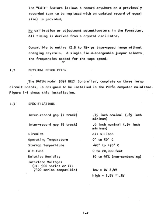
PHYSICAL DESCRIPTION
[image:8.620.69.583.54.759.2]The DATUM Model 5091 NRZI Contro{ler~ complete on three large circuit boards, is designed to be installed in the PDp8e computer mainframe. Figure 1-1 shows ·this installation.
l' •
3 .
S Pi: C I F I CAT ION SInter-record gap (7 tra~k)
Inter-record gap (9 track)
C i rcu i ts
Operat'ng Temperature Storage Temperature AI t i tude
Relative Humidity Interface Voltages
(DTL
900 series or TTL7
LlOO ser ies compat ib Ie).75 inch nominal
(.69
inch minimum).6
inch nominal(.54
inch minimum)All s i I icon 0° to 50° C
_400
to +700
C
o
to· 20,000 feet10 to9~h (non-condensing) low &: OV
±.4v
THREE BOARDS; REQUIRES FOUR SLOTS
TAPE
MACHINE
#1
CABLES TERMINATE HERE
TAPE
MACHINE
#2
o
o
INTERCONNECT ASSEMBLY
76258
Figl!re 1-1. I nsta11ation of Model 5091 NRZI Controller
The i nterfncc i 5 des i gncd 'such tha t an open c i rcu i t i s i
nter-preted as Cl "h ;gh" signa 1 •
Figure 1-3 illustrates the configuration for which the interface
has been designed.
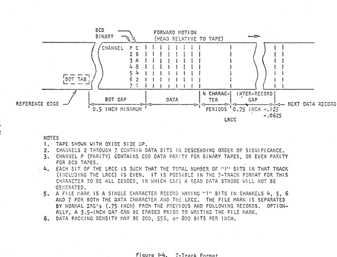
1.4 MAGNET I C TAPE FORI1ATS
r - - - i
r---~---I. CABLE
I
I
TERMINATIONI
I I +5V I
I CABLE DRIVER I -CABLE RECEIVER I
I
I
220n I:
~J~---I----~~---~___
r - :
I I
I
IL ________
~L _ _ _ _ _ _ _ _ _ _ _ _
J
DTL 84l~ or TTL 7416, 7J·~37. DTL 8XX Series; TTL
7
1lXX Series7438,
7~40 or equivalent or equivalentBCD ~ FORWARD MOTION
_ _ _ _ _ _ _
/~BiNARY ~~"_
_ _ _ (_HE_A_\D_RtLATI"E TO TAPE)-:'/~
)P C I·
\ 2 B 1
r:--~)
~~
: :
\
I.
I
I
I
R::FERE~CE EDGE
~o~ ~.B.J
(I
_____
~_~_:
__
~_:
_________ __'(
J
h=-S-B,
NO_TC-H-GA-,M'P_'IN-'.I-MU'M~:-
_ _ DA_T_fJ. _____ ...._!:
~~RA:I~ ~T:~;~ECO~:l:_
NaT DATA "ECORDv. PERIODS 0.75 INCH +.lL5
LRCC - .0625
NOTES
1 .. TAPE SHOHN WITH OXIDE SIDE UP.
2. CHh~~ELS 2 THROUGH 7 CONTAIN DATA BITS IN DESCENDING ORDER OF SIGNIFICANCE.
3.
CHA~~NEL P (P/~R.iTY) CONTAI NS COD DATA PARiTY FOR 5iNARY TAPES, OR EVEN PARiTYFOR BCD TAPES.·
4.
EACH BiT OF THE LRCC IS SUCf-l THAi THE TOTAL NUM8ER OF Ill" BITS IN THAT TRACK (I;JClUDiNG THE LRCC) IS EVEN. IT IS POSSiBLE IN THE 7-TRACK FORt·1AT FOR THIS CHARACTER TO BE ALL ZEROES, IN WHtCH CA~E A READ DATA STROBE WILL NOT 8E5.
A FILE t·:ARK IS A S!NGLE CHP\F\ACTER RECCRD HA'flNG 111" BITS IN CHANNelS4,5,6
AND
7
FOR BOTH THE DATA CHAR.l\CTEF. I\ND TH~ LRCC. THE FI LE ~1.A.RK I S SEPARATEDBY NORMAL IRG's
(.75
INCH) FROM THE PREVIOUS AND FOLLOWING RECORDS. OPTION-ALLY, A 3.5-1NCH GAP CAN BE ERASED PRIOR TO WRIT!NG THE FILE MARK. [image:12.795.40.715.62.577.2]I
~
n
r:C-= -AS' ~"
I
:.J
- -
1
fi
/'
~EFERENCE
--!::-o FORWARD MOTION (HEAD RELATI VE TO
TAPE)I----::>-CHAi\NEL 4
6
0
1 2 p3
75
I
I
I
I
It
I
II
I
DATAI '
t ,
i I II
II
I
I f I I I JI
,
f'~
J
BOT GAPI '
EDGE INCH M' Nl
i1w:r~
,0.5
t
l
'.4 CHAR.'AC- 4 CHA. ?Jl.C_I
I
...
' .
'"
TER TER ~
--::"1<
PERI ODS-r~PERIooSt
:1 NTER-RECORD J NEXT DATA RECOKDCRCC
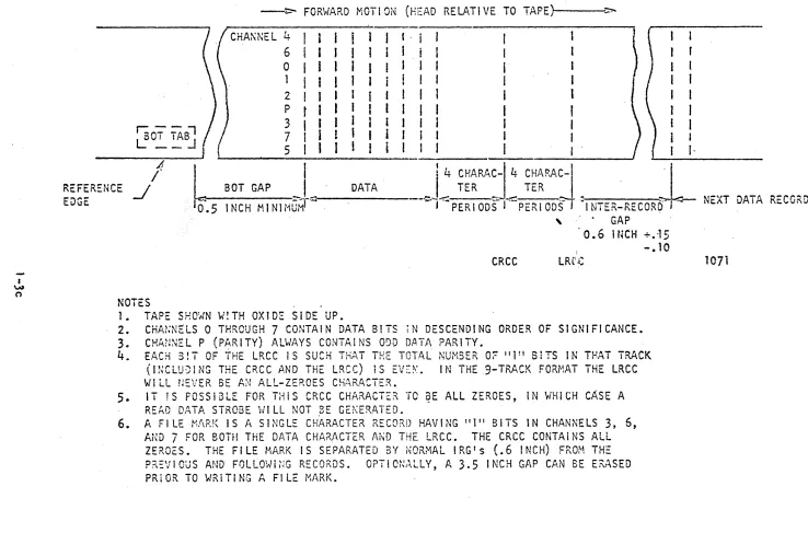
NOTES
1. TAPE SHO~N w!TH OXID~ SIDE UP.
, GAP
" 0 • 6 Hi C H +. -15
-. 10
LRC.c
2. CHA~NELS 0 THROUGH
7
CONTAIN DATA BITS iN DESCENDING ORDER OF SIGNIFICANCE.3.
CHAN~EL P (P~RITY) ALWAYS CONTAINS O~D DATA PARITY.4.
E.L;CH 3!T OF THE LRCC IS SUCH TnAT THE TOTAL NUriSER 0;:- "l!! SiTS IN THAT TRACK(INCLUJING THE CRCC AND THE LRCC) IS EVE~. IN THE9-TRACK FORMAT THE LRCC
WILL n::VER BE A:\! ALL-ZEROES C!1P .. RACTEK.
5.
IT 1S POSSIBLE FOR THiS CRCC CHARACTER TO ~E ALL ZEROES, IN WHICH CASE AREAD DATA STROBE WILL NOT 8E GE~ERATED.
6. A FILE l"'l\F:K IS A SINGLE CHARACTER RECORD HAVING "1" BITS IN CHANNELS 3, 6,
AND
7
FOR BOTH THE DATA CHA?-ACTER Ai~D THE LRCC. THE CRee CONTA I NS ALLZEROES. THE FILE MARK IS SEPARATED 3Y NORMAL IRGfs
(.6
INCH) FROM THEP?\~VIOUS AND FOLlOHi~~G RECO~DS. OPTlm~J\LLY, A 3.5 INCH GAP CAN BE E~ASEO
PR10R TO WRITING A FILE MARK.
Figure 1- 5. 9-Track Format
[image:13.792.27.765.67.554.2]SECTION II
INTERFACE
2.1
INTRODUCTION
There are two interfaces to the Cont '''0 11 er' Format ter sect ion, one
to the computer adapter section and one to the tape units
(76232 AI, A2,
Cl and C2).
Individual, stranded, 22-26-gauge twisted-pair wires should be
used. Maximum length should be twenty feet (total) for .the tape-unit
"Daisy-Chain" bus.
The twisted-pair wire should have at least one twist per inch and
a minimum insulation thickness of .01 inch.
The ground wire of each twisted pair should be terminated to
grqund as close to the origin or destination of the signal as possible
{within 6 inches maximum} to minimize ground-loop-current "crosstalk"
effects.
2.2
FORMATTER/TRANSPORT(s) INTERFACE
2.2.1 Formatter to Transport
Transport Address
SELECT A through SELECT D - Transport Select Lines. Four select
1 ines to select one of the "daisy-chained" transports. Developed by decoding
2.2.1.2 Control
The control 1 ines activate the selected transport when it is
"READY II and liON LINE".
SFC - Synchronous Forward Command. A levelwhich, when low,
causes the selected transport to "ramp" up to speed and drive forward
at the rated speed until the level goes back high. When switches to the
high ievel, the transport IIramps" down to halt.
SRC - SynchronoLis Reverse Command. A level which, when low, causes the same action as SFC except in reverse. tape motion.
RWC - Rewind Command.
A
negative-going pulse which causes the selected transport to rewind to load point.OFC - Offl ine Command. A negat ive-going pul se which causes the selected transport to revert to manual control. Transport must be
manually placed liON LINEII before it can again be operated.
'.
The offline command can be transmitted to a tape transport that
is rewinding (even though the transport status indicates NOT READY).
SWS - Set Write Status. The level of this signal is inspected
within 20 microseconds after an SFC or SRC cOl11l1and is initiated to set the
.selected transport to the write or read mode. This mode is maintained
unt i1 . the nex t SFC or SRC command is in i t i ated.
The write nude within the transport is also switched to read mode if:
a) An RWC or OFC command is received.
b) Loss of interlock occurs.
c) The transport is manually switched offl ine.
EDIT - (Over Write). - This signal is a level that causes the
trans-port write current enable/disable to Ilrampil on and off to minimize rate of
change of recorded inter block gap magnetism when rewriting a record in the
EDIT mode.
This signal level also causes the DC erase head current to be turned
off immediately after rewriting the new record (to keep from erasing the
be-ginning of the next record).
WARS - Write Amplifiers Reset. This signal controls the early ramp
down of write and early turn off of erase currents after rewriting a record
in the EDIT mode.
The negative-going transition of this signal initiates the write
cur-rent ramp down. In NRZI transports, this signal also generates the LRC
char-ac te r.
DDS - Select High Density. Low
=
select high density (for NRZIFor-matter only) for 7-track transport.
2.2.1.3 Write Data
WDS - Write Data Strobe. This is a clock used to copy the write data
(WDP and WDO through WD7) into the selected transport write flip-flops. The
data levels must be static during WDS and the trailing e~e (positive-going)
of WDS is used to clock the flip-flops. The clock rate is at the character
rate for NRZ I.
WDP, WDO through WD7- Write Data. WDP is the parity bit, WDO is the
--
--most significant bit, and WD7 is the least-significant bit. WDO and WDl are
not used for 7-track NRZI operation.
These signals are presented to the selected transport along with the
WDS clock. The write data is presented in a logic-level form (low
=
logic 1,2.2.2 Transport to Formdtter
2.2.2.1 Status Li nes.
ROY - Ready. A level that is low only when the selected
trans-port is:
a) Interlocked
b) Through the initial load or rewind-to-lo~d point sequence.
c) On I j ne
d) Not rewinding
Note:
A
transport may go NOT Ready for approximately .5-secondafter reversing into load point and does not go Ready until approximately
.5-second after termination of a Rewind.
ONLINE - On I ine. A level that is low when the selected trans-port is manually switched on I ine (to place it under remote control).
REWINDING - .Rewinding. A level that is low while the selected transport is rewinding. The level remains low until the transport completes
the automatic "return to load point" sequence but the transport does' not
become Ready until approximately
.5
second after the R\JO signal terminates.FPT - File Protect.
A
level that is low when the selectedtrans-port has a supply reel of tape mountep that does not have a write-enable
ring ins tall ed.
lOP - Load Point.
A
level that is lo~ when the selected trans-port's beginning-of-tape reflector is located under the photo sensor,inter-locks are made, and the initial load or rewind sequence is completed.
EDT - End of Tape.
A
level that is low when the end-oF-tapereflector is' under the photo sensor in the selected transport. This signal is not staticic;ed and neither- the positive nor negative-going transition
is" c 1 e a nil •
SINGLE/DUAL - Head Stack. A level that reports the selected trans-port head type. Low for single stack, high for dual stack Ilread while writingl l
•
2.2.2.2
2.2.2.3
7 TRK/9 TRK ~ Transport Type
Low
=
9-track High = 7-track001 - Data Density Indicator
Low
=
High Density Selected High=
Low Density SelectedRead Data & Read Clock
RDP, ROO through RD7 - Read Data
Read Data & Clock
The read data is completely IIbufferedl l in a special register. The
da-ta is allowed to change until just before the leading edge of the read strobe
pulse (RSTROBE) and is static throughout RSTROBE and until a minimum of 1 ~s
af-ter RSTROBE.
SECTION I II THEORY OF OPERATION
3. 1 I NTRODUCTI ON
This section con~ains information on the operation of the NRZI Mag-netic Tape Controller.
The information in thi~ section is divided into two major topics. A discussion of the block diagram (Figure 3-1) is presented first, to provide
an overall functional description and to illustrate the .relationship between
the formatter portion, the adapter portion and a discussion of the command
execution, illustrated by timing diagrams, describes operation of the Con-troller circuitry during execution of computer-originated instructions.
The Controller performs three basic functions. These are:
1. Control
2. Write 3. Read
The Controller provides control over the selected tape unit
includ-ing all timinclud-ing necessary to perform automatically all Write, Read, Rewind, Space Forward or Backward, and Rewind' commands.
Upon completion of the commanded operatio~, status is provided so that
the co~puter can ascertain whether the operation was performed correctly.
The Controller performs all the Write functions for erasing tape,
writing a file mark or writing a record of data. A 3.5-inch gap is automati-.
cally erased before the first record when starting from beginning of tape (BOT). The correct timing delays for erasing the inter-record gap (IRG) are provided·
\N
I
-OJ
"~Zl 7/9 j~;'C~ NRZI rOKI'.ATTE~
IT'"
\T':'?C:
;~;~ t:~'1 T
Ie
t';'~~:~ilC T.;?:: ":"VC;S?O"T
r
S'e~A , • ,... _ _ _ _ ...., _ - - - -_ _ _ _ _ _ _ _ _ _ _ _ _ _ _ _ UNI. ... _ _ _ _ _ _ _ _ SELECT -1 COMI'UTE~ AOAPTC~,Ii;'?:: 1-r;'PE !""'s;::;-1
k============ ________________________
-j~!\IT liSIT~!" •• :
I
TA?E U"'T'*'
8 A _ S
lc~'~SELECT
,
~i
I
SietJ S·,.' I TCHES FC:t:~ATTER~ 3.~W @
AI)::lR
SELECT
01
FActI t
I
I 1I
I
I
I
II
1 SFCC
f'~'y
T" ... <;"'O"'~
;:::::::STATES
ICO"""""
k:::::::::;-:::=======CO~M~,MA~N='::l=S=============t
I
l;i~ ~;;~1;2 C~-::~K;l"'Ob-d .,;"~:;~R
0nr
V
I
'1~;:FCJj;';i}J
':. REVAO,J
~
ICO-;T?~L~E;"~t,;~y,:~1
STATES!~6~~~~R
l:=
~~~~o
CLeCK.
t
"VAll 0 CLOCK"j
ANO ~AI N r.7'\E
STA-US .I
I
WRITE . cc~nROL '& I ': : 7 • unml
ll~~~R~cr ,.0_2_J~~.::::::::::::::::::::::::_~~~~~~V~A-l_t~O~C~l-O_C~K~~~~~~~~~:
:f
STAiUS
"
STR03t: C
REJECT
STAn;s
~.
I
ISTAT1.:s ~I ~~Gl STER@0F>
7 TRKI
I P.os T O£A. "'.O'E ~J
REA. STROSE:
~~~~ A:~~~~~~~~.~~LI
______
--1-_ _ _ _ _ _ _ _ _ _ _ ...==================
T.
<EA> 'ArAeb' "',-...
,,,_,;.R PARITY 000 PARITY~1.._CPAC_NR_~~_O~
_ _(,"";\~I~!-.-1
TR, 6 .I p:,ql TY
f "
~f<-- ~ ~EN ODt' ;>~~!:rCHECK
STATES
(CR3)WRITE
DATA
SELECT
CATES
PoAlT WRITE
STORAGE
SH MTA RUilSTER @~ ... ==========~ -'--'--~ _ _ _ -r-_~~!:J Ii2' _ CO;·\;'I\',:> FL';G
~
i
C
RE:;ISTjJC.? .7 Tit~ C---'l---~
r::~====== SET DATA FLAG CATA TAANSFE? OATA FLAG
~
=t
STATES
1,/fR. ACK . ' CONTR01l26\27/fi\I~---i W/~ ACKNC\ll!O::EOdAY STATUS ~AlT . ' . \!..;I"d JoI.A\.T
COU:HE:R(S'I - SPEED
.~~
CLOC;.:.K:.-____ -.
~
L -_ _ _ _
I __ _
~-:OL..---, 000
r
\JR I TE--- PARlTY CLOCK
~----I 7 TRK ' - - - .
(5)
STATES
\!.V I r:ESET CC~I'.ANO
7 iRK
. 6·
HI OENSITY SELECT
(CR10)
I
wDA~TIAl!
) [~tl k:===~===~~===-:.-~-c~-~<?~
..--___
.1.-_---,1 7 } CRec
GEN. -
1]
READ _ IIt\TER-RECORO }--. U!;l.AY ~Eg~TERSir.C:>'~S ::>;1 GAP DETECi IJ'4'I CC:;~iTEf\
\ (~ TAACK. ~ • ~~ \!..~ ~C CLOC!( HALT
The task of writing is reduced to mere transfer of the characters on
a demand-response basis for the computer-adapter logic.
The Controller also reduces the reading and spacing operations to
a minimum by performing all parity checks and positioning of the head in the
IRG's automatically. The task of reading is reduced to transfer of the
char-acters on a demand-response basis.
The Controller can accommodate as many as four magnetic tape
trans-port units simultaneously. All input/output signal lines are daisy-chained
to the tape transports. Only the selected tape transport unit will respond
to the Formatter commands. Select is determined by unit-select switches
loca-ted on each tape unit.
3.2 BLOCK DIAGRAM
A simplified block diagram of the NRZI Formatting logic is shown by
Figure
3-1.
The block diagram illustrates the various functions performed bythe standard 7-track, 9-track NRZI Controller and shows the relationship
be-tween the control, the tape transport units, and the computer adapter section.
3.2. 1 Command Register & Valid/Reject Logic
When a command is output from the computer, the command and a strobe pulse are delivered from the computer-adapter segment to the Controller
valid-command-detect log i c. I f the command is acceptab le, a "va 1i d" clock is gener-ated to enable the command to be loaded into the command register. If the
com-mand is not valid, a Ilreject" pulse is returned to the computer adapter. Each
"valid" clock initiates a system reset (SRS) pulse, which is, in turn, used to
reset the Formatter to initial conditions.
3.2.2
CBUSYThe "valid" clock also sets the controller-busy flip-flop. The
controller-busy flip-flop normally is used by the computer adapter to signal termination of all commands. The transport control logic resets the
control-ler-busy flip-flop after all tape motion has ceased for the commanded
func-tion. If "on-the-flyll writing or reading is de'sired, the Data Busy status'
must be utilized by the computer to initiate the next command as soon as Data Busy terminates.
3.2.3
Transport ControlThe transport control logic develops the forward, reverse, rewind
and offline commands to the selected tape transport unit under control of the command register and the state counter.
3.2.6
State Counter and Main ControlThe State Counter breaks the major operations (such as write and
read) down into successive sub Iistatesil that are sequentially stepped-through
to perform the operation. These states are:
State COllnt Function
---~ Reset
o
1
2
3 4
Predelay (not BOT, and not 3-inch gap) Predelay (BOT or 3-inch gap)
5
6
7
Write or Read execution Postdelay
Forward Motion Halt time out ,Reverse Motion Halt time out
Rewind or Clear execution
The "delay" and "time out" states all use the Delay ,Counter to
determine when the state count should terminate and the next state count
entered. These delay count times vary, depending upon such factors as:
1. Tape speed
2. Single or dual-stack head
3. Edit or normal mode
4.
Reverse or Forward motion5.
Seven or nine track tape unit selectedThe pre and post delays are used to erase the inter-record gaps
(IRG) and to halt the head in the correct position in the IRG when reading.
~
State 0 (the "rest" state) is the state the Controller enters after
completing an operation.
State 1 (Predelay) is used to wai't for the tape unit to get up to
speed ~nd to erase part of the IRG when writing. State
when not starting from BOT or not erasing a 3-inch gap.
is used for, predelay
State 2 (Predelay) is similar to State I except a longer delay is
implemented to handle the 3-inch gap erased automatically at BOT and the
Erase-3-lnch-Gap command.
State
3
(Write or Read Execution) is the State during which therecord is written or read. When reading, StClte
3
is terminated when no moreRead strobes occur (indicating the IRG has been reached).
I,RG detection also tetminates State 3 for Write operations when
using a dual-stack read-after-write tape unit (so that the written record
can be checked for correct, parity). For single-stack wl-ites, State 3 is
terminated as soon as the LRC character is written at the end of the record.
State 4 (Postdelay) haJts the head in the correct position in the
'!RG when reading. When writing, State 4 postdelay erases a portion of the IRG.
State
5
(forward motion halt time out) retains· memory of the forwarddirection of motion during the time between the command to stop and the actual
stop time •. This delays termination of the CBUSY signal until the tape unit
has completely halted in the IRG.
The OBUSY stntus terminates when State 5 is entered. Thus,
suc-cessive "Writes" or sucsuc-cessive "Reads'! may be executed on-the-fly, without
stopping in the IRGls.
State 6 (r~verse motion halt time out) is similar to State 5 except for rev'erse mot i on commands. When performi n~ 011-the- fl y ope rat i OilS, success i ve
commands issued after OSUSY terminates but before CBUSY terminates must be of
the same type. A Read cannot follow 'a Write and a forward motion command
can-not follow a reverse motion command (or vice versa). There is, of course, no
such restriction if the commands are not issued until after CBUSY terminates.
State
7
(Rewind or Clear) is entered upon issuance of a Rewind orClear command by the computer. The state is terminuted when the tape unit
3.2.7
Status RegisterThe Status Register stores both the tape unit the the Controller
status. This makes it possible for the computer to inspect the results of
an op~ration to find out whether it was compl~ted correctly or if some other
action must be taken.
The status of the selected tape unit and the Controller are
avail-able for access by the computer"at any time.
3.2.8
Parity ControlThe Parity Control logic provides manual or program control over
selection of odd or even parity for 7-track tape units. Odd parity is
automatically selected for 9-track tape uni ts. The output (odd pari ty) is
. used by the Parity Generator and Check logic.
3.2.9
Parity Error DetectThe Parity Error Detect logic searches for one or more parity
errors in each tape record. Any detected errors cause the Parity Error
Status bit to be set.
The Read Control logic uses the Read Clock Activity Sense logic
(RCAS) output to enable the Parity Er'ror Detect logic'to inspect the
Charac-ter Parity Check output
2!l!Y
during the data portion of a record (-since CRCC(9-track) and LRCC (7-track) can exhibit either odd.or even parity).
The output of the LRC Check logic is inspected only after the
entire record (including CRCC and LRCC) has been read.
3.2.10 CharClctcr P~'!y~,cck ;
The Character Pu·rity Check logic checks each character read from
tape for either odd or even parity.
3.2.11 LRC Check
The Longitudin~1 Redundancy Character Check logic checks for an
even number of l's for each individual track down the length of the record.
including the CRC and LRC cha\'o-c:ters.
3.2.12
Read Data Storage RegisterThe Read Data Storage Register store? each tape character at the
leading edge of the Read Strobe in such a manner that the Read Data is
sta-tic to the computer adapter interface throughout the entire period until the
leading edge of the next Read strobe occurs. This deletes the requirement
for a storage register in the computer adapter section. This register would
otherwise be required to retain the data for the maximum possible time after
the Data Flag is set, to give the computer the maximum amount of time to
accomplish the data transfer.
The outputs of the Read Data Storage Register are routed to the
rest of the logic where Read·data is util izedon the Controller.
3.2.13
Read Clock Activity SenseThe Read Clock Activity Sense logic separates the data portion of
each record from the CRC and/or LRC characters in the forward direction.
Thus, the Set Data Flag (in the Read Control logic) is allowed to operate
only for the data portion C'f the record, \\fhich "strips" off the CRC and/or
The' check word count (CI\~JDCNT) pul se occurs just after the last
data churactcr but before the CRC or LRC charucter's Rcud'Strobe destroys
the contents of the Read Data Storage Register. The CKWDCNT pulse is
delivered to the Computer Adapter interface, where it may be used to create
an extra data transfer request to the computer for the case where an odd
numbe r of cha rac te rs We re read f rom tape and the "Pack" mode of OpC ,~a t j'on
is being used., The CK~JDCNT pulse is also typically used by the Computer
Adapter to determine if the expected number of characters were read from
tape to create status bits which can inform the computer that the record
was too long. too short and/or contained an odd number of tape characters.
~
3.2.14
File Mark DetoctThe File Mark Detect logic checks for 7-track or 9-track file
marks. depending upon which type of tape is selected. The EOF status bit
is "developed if a file mark is detected in a forward or backward direction.
3.2.1'5 Rc~d Control Logic
The Read Control logic,controls data transfer during State
3
untilthe IRG is detected, at which time the Postdelay (State 4) or one of the
Hal t delays (Stute 5 or 6) is entered.
The Set Data Flag signal is generate~ for each Read Strobe that occurs as long as RCAS indicates thai the data portion of the record is
present and the Halt signal hasn't occurred.
When the IRG is detected or the computer generates the Halt signal
(to indicate that it doesn't want any marc data). there are no more Data Flag
signals generuted even though there may be more data in the record.
The Read Control logic also controls the forward and reverse space
operations. These operations are identical to reading forward or reverse
except that the Data Flag is not set for data transfer requests. All parity
checks are valid for the spacing operations as well as for the reading
opbr-ations and for read-aft6r-write operopbr-ations whe~ a dual-stack head is employed
on the selected tape unit.
In the special, Test Read, mode, the CRC and/or LRC characters are
not separated from the data in the Forward Read operation. This mode is used
to check the CRC and LRC generator logic with diagnostic programs.
~
3.2. 16
Write Storage-RegisterThe Write Storage-Register is provided so that the Computer Adapter
does not need a register to store computer output data. The Data Transfer
logic operates on a request/response basis via the Data Flag and Write/Read
Acknowledge (\1/R ACK) si gnal s. Each dcJta character is requested a full
write-clock-period before it is needed. The computer can respond any time
within this period with a W/R ACK strobe pulse to load the Write Data into the. Write Storage Register.
3.2.17 Parity Generator
The Parity Generator creates odd or ~ven parity for each character
presented from the Write Storage Register and sends the parity bit to the
Write Data Select Gates. The Parity Control logic detennines whether odd
or even parity is generated.
3.2.18 Write Data Select Gates
The Write Data Select Gates consist of three sets of gates that are
enabled by the Write Control logic to gate the Write data (and parity bit) or
the File Hark code or the CRC Character onto the write data bus to the tape
3.2.19 File Mark Generator
The File Mark Generator generates the appropriate file mark. This
may be a normal 9-track file mark, a special 9-track file mark or a 7-track
file mark. The Write Control logic gates .. the file mark code onto the write
data bus at the appropriate time and generates a Wr~te Clock to write the file mark.
The special 9-track fi le mark is an option that writes the 7-track
file mark code to provide compatibi·lity with some computer manufacturer's
"
hardware and software when writing in the "unpack" mode on a 9:-track tape.
3.2.20 CRCC Generator
The Cyclic Redundancy Check Character (CRCC) Generator calculates
the CRC Character while writing each record as each data character while
writing each record as each data character appears on the write-data bus.
At the end of the record (9-track only) the \1r i te Control logic gates the CRce onto the bus and generates a Wr i te clock pu.1se to wri te the
CRe Character. The LRC Characte r is then written to finish the record. The CReC may be a 11 zeros and may exhibit odd or even parity.
3.2.21 Write Control Logic
The Write control logic operates during Stiltc 3 for write, erase
~nd write-file-mark operations. The Write control logic controls th~ Data
Transfer logic for write operations by developing the Set Data Flag pulse
to request each character to be written until the Write operation is
termi-nated by the Halt signal from the Computer Adapter.
Upon receiving the Halt signal, the CRC and/or LRC character is
automatically appended to the record and part of the ~RG is then erased.
If a single-stack (read/write) tape unit is sele~tcd, the Write Control
logic triggers the State Counter to the State 4 postdelay when it finishes
writing the LRC Character at the end of the record. If a dual-stack {read after write) tape unit is selected, the Inter-Record Gap Detect logic is
utilized to exit State 3 to State 4 postdelay in order to allow all of the record to be read-after-write parity checked.
The data rate is devel~ped from the write clock frequency (from the Crystal Oscillators) and the tape-speed-select 16gic.
The Write Control logic also sends the Write Most Significant Byte (WRMSB) signal to the Computer Adapter. This enables the odd/even
characters to be separated when "unpacking" a computer word into two
sequential tape characters.
3.2.22 fLystal Osci 1lalors and Tape Speed Select
The Crystal Oscillators provide stable precision clock frequencies
for packing densities of 800/556/200 bits per inch. One set of crystals
covers the standard tape speeds from 12.5 to 75 ips. The Tape Speed Select and Density Select logic divides down the clock rates to the appropriate
frequencies and selects the write clock frequ~ncy as determined by tape speed
and packing density.
The Speed Clock signal is used by the Delay Counter to provide
'3.2.23
Density SelectThe Density Select logic provides control over selection of Hi or Low density for 7-track tape units. Nine-track tape units are automatica'lly operated at only 800 BPI. The Densi ty Selectictn is controlled by the com-puter program via the Hi Density Select signal.
3.2.24
Data Transfer ControlThe Data Transfer" l:ori'tjO"" operates in conjunction wi th the Read or Write Control logic depending upon whether a Read or a Write operation
is acti vee
The Read or Write Control logic generates the Set Data Flag pulse to signal that Read data is ready for input or to request a Write Data char-acter. The Computer Adapter returns the W/R ACK signal, which clears the Data Flag and is used to strobe the Write data into the Write Storage Regis-ter for '\~rite operations. When the Computer Adapter dcsi.·cs to hnlt data transfer, it generatcs the HALT signal and the Data Flag signal is disabled.
3.2.25
Delay CounterThe Delay Counter is a flip-flop divider chain that counts the Speed Clock pulses to provide precise time intervals for Pre-, Post-, and Halt delaY5. The time interval begin~ when the counter starts counting
(from a reset condition) and ends when the STOP signal is generated by the gates that decode various counts from the Delay Counter. The gate se~ected
fora p.articular time interval depends upon which state the Controller is in as well as its configuration and the selected tape unit (provided by the STATUS signals, to the Delay Counter).
3.2.26
Inter Record Gap DetectorThe IRG Detector triggers the Formatter from State
3
to. the PostDelay State 4, of Halt Delay State 5 or6 when completing any Read or Spa~e operation or any Write operation with a dual-stack, read-after-write tape
unit. The IRG Detector resets the Delay Counter with each Read strobe.
After the Read· strobes stop, the Delay Counter is allowed to cOllnt for a
pre-scribed interval until the STOP time is reached, at which time State
3
isterminated.
3.3
COMMANDS3.3.1
Basic CommandsBasic Commands provided by the Formatter are:
1 • Read (one record)
2.
Wri te (one record)3.
Space4.
Wri to File Mark5.
Erase 3-inch gap 6. Rewind7.
Offline8.
Clear3.3.1.1
Read and Space.The Space operations can be a single or mUltiple record under control
of the 'STOP SPACE Computer Adapter signal. In addition, the backspace operation
can be conducted in the EDIT mode. This is to position the Write head correctly
in the IRG preceeding a record that is to be replaced with an equal length but
3.3.1.2
Write, Erase3
Inch Gap and Write File M~rkThe Erase-3-lnch-Gap command can be performed by itself or combined with the Write or Write File Mark commands to cause a 3-inch gap to be erased prior to writing the record or file mark. A Write command can be performed
in the Edit mode (if the record to be replaced has first been backspaced over in the Edi.t mode to position the head correctly) to replace a record with an equal length record of updated information.
,3.3.
I .3
Rewind and OfflineThe Re\-Ji nd command causes the sel ected tape uni t to rew; nd to Load
Point (Beginning of Tape). The Controller goes "Busy" u'ntil the re\-/ind is terminated (to p~ovide a means of interrupting the computer upon termination of the operation).
The Offline command never sets the Formatter to the "Busy" state and maybe sent to a selected tape unit even if the tape unit is "Not RCud1,II
because it is performing a rewind operation.
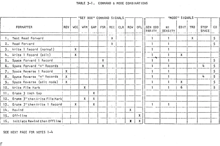
3.3.2
Command and Mode CombinationsThe list of possible commands executable by the Formatter depends upon the "mode" lines and are listed in Table
3-1.
NOTE I The GEN ODD PARITY and HIGH DENSITY mode lines are ignored for 9-track tape units. The GEN ODD PARITY line controls whether odd or even parity is written or checked for. The HI DENSITY
line controls the written character packing density and the period of time allowed between read strobes in the Read Clock Activity Sensor Circuits.
TABLE 3-1. COMMAND & MODE COM B I NAT IONS
"SET XXX" COMMAND S I G NALS t~ I 'MODE" SIGNALS
r
~
_ _ _F_O_R~_MA
__~~~R
_ _ _ _ _ _ _~_~W_C_C: ~:~l-~~-~~_~j
.R_CC
I._~~~I
REW
~F
__ L1!~~'~~~J--PE~~'.TYI_ED,~t~R~
___
~;~~EI_~D
j
Test Read Forward
I
-r-
--I-'xl
--J~~~--
-
1 1 XI
!
5I
---~-~-~~~I·--L[--I ~--i
-!5--1I I
I
i
I I,
I 1 •
i
I 2. Read Fon':ard
I
I ___
x_ I I I I I
---~-;r-it-e-l-R-e-co-r-d-(n-o-r-ma-l-)-~-~-X~-~-~-~i--,---1.1
1 1
i
j
'-I'
Wr i te 1 R.ecord (ed it) X ----,---- . - -
[--1'
1 XI
r-! - - -
i--:----+--+--r--t---I---
-
-' --,
I
i
3 .
I
,
I
4.
Space Forward 1 Record
---:--~-_t·--+---t--I
I
5.
I
6.
i
7. Spece Reverse 1 RecordI
XI I
I
8.S~~ce -R~:·~;~·~-:-,~" R~~-ords
I
X!I
4 · 5I
I
11. Erase 3 I nch Gap~
i
I
f 12. Erase
3;;-~h:_n y:rite!~!..:!i~r
__k_~l
_ __'_! _-r-_X-t ___~
--{.-J--, __
L II
i
.
I
II
Ii-:-:t_-_;'_::_~_~_~-_:~_'t
__
h_e_n_~!_~
__L_~e_!_--_p~e
__~?_r:_i-
_____
I
-1=~f=~'1
xi
Xlit'
l -i
l
--j---I
I
I
I
_1_5_. _I_n_i t_i __ a_te_Re_w_i_n_d __ t_he_n_O_f_f_l_i _ne ___ !
_-,--_~_
...r_-= ...
r_-__ -_-....,_---_---:...:-_-_-i~
-eXI
X : _ _ H _--'--I----l
;--1
\N
[image:34.793.36.746.83.554.2]Input/Output Trdnsfer (lOT) Control Pulses
The memory extension register allows the three least-significant bits of the computer AC register to be stored in the computer adapter memory-extend register to provide a three~bit extension of the address to the com-puter. Control and status information is transferred via lOT instructions by the program. In order to effect transfer of the control and status infor-mation, the lOT decoder is utilized to gate the three lOP pulses (IOP1, IOP2, and IOP4) to the various logic elements of the computer adapter when the six-bit device-select address co~ for the tape controller is present on the computer
MB
register bus. The lOT control puls~s are referenced on the block diagram by the actual octal lOT instruction cod~. The fol'lowing gives the basic uses of the ·IOT's by octal code.OCTAL COO'E
-6701
INSTRUCTION
Skip on Error Flag or MTF set
-~---.
- - -
.. ---. -_. -_._-_._---_ .._-_
.. -.._---6702
Clear il,.C----_._ .. -..
-._---_
... -. '-._.-.. --.. .-6706
St at us --'(;-AC-'-' .---.---.---~,
-6i11 Skip on Controller Ready
. __
._---_._---.:!:2.1!: ..
~
__ .
(,
1~~!_~~_~_~_~
_
~~~_.~~~~.r_~_l.
__ ~:~!_~~~~-~--.---6714 Inc 1 us i ve -OR AC -~ Cont ro 1 Reg is te r---_._---.-_.-.. _--- . _ ...• _._.--
---6716 AC~~ Control Register and Clear Error Flag/MTF
-:'6717
·---Ac~-~-·C-~;;_t-~_;;l·-E·~e~s i~~-·Reg~·t;;_(M~de, - Offl i n-e-,-M-e-n-,o-r-y-E-x-t.)·---
...~---~-AC
~
6 7 ~_~ __ l ~_~.l
1 X X X X X
=
Offl ine ModeX X 1 X X X
=
Edit ModeX X X 0 0 0 ::: 1st
L:K
of core memoryX X X 0 0 1 ::: 2nd 4K of core memory
X X X 0 1 0 ::: 3rd IlK of core memory
X X X 0 1 1
=
4th ItK of core memoryX X X 1 0 0
=
5th 4K of core memoryX X X 1 0 1
=
6th 4K of core memoryX X X 1 1 0
=
7th 4K of core memoryX X X 1 1 1 ::: 8th 4K or core memory
-6721
Skip on Tnpc Unit ReDdy -6722---
MTGO
(initiute commund),---
-... -.-....•.._._._.-
•... _ ... .--_
••....3.9.4
AC OutputsThe twelve outputs of the Computer Accumulator (AC) register arc
wired to the inputs of the Computer Adapter conirol register, the
Control-Register Extension and ~he Prog. 1/0 option to the Write storage register. lOT
6714
''Jill "inclusive-OR" the AC register into the control register."lOT
6716
will replace the contents of the control register with thecon-tents of the AC regi ter." lOT
6712
wi 11 clear the control register andthe MTF or the EF. lOT 6717 will load the AC register into the control
Extension register.
AC Inputs
lOT
6706
fir~t clears the AC register, then gates the contentsof the status register through the input gates to the AC register. Since
the AC register is cleared automatically by lOT
6706,
there is no need forthe program to clear the AC register first.
Interrupt/Skip
Control register bit
9
enables the interrupt logic so that thecomputer is interrupted if either the EF or MTF flag is set. The" program
may test for the tape controller Interrupt by generating OPT
6701.
lOT6701 will cause a skip pulse to be generated j"f either the EF or MTF flag is set. lOT
6712
may then be used b~ the interrupt subroutine to clearthe interrupt flags. The computer program may also test for Tape Transport
Unit and/or Tape Controller Ready by using lOT
6721.
to test for TransportOnce the control codes have been transferred into the computer
~dapter control register, the tape-transport controller can be signalled to
initiate the operation defined by the decoded commands by execution of lOT
6722 (Mag Tape Go). lOT 6722 causes the STROBEC pulse to be generated. The
STROBEC pulse then transfers the decoded command into the tape transport
con-troller command register (if the command is a "valid" one)· and initiates the operation. When the operation is complete, the status lines may be sampled
by the computer program to test for satisfactory completion of the operation.
The computer program is signalled that the operation is complete by the EF·or
MTF flags. These two flags are set from the tape transport controller 2-CBUSY
"
flip-flop, and generate an interrupt if bit 9 is set in the control register.
If the·command is not a valid one, the "Reject" status bit is set and the
Error Flag is set.
Actual data transfer into or out of core memory· is controlled by
th~ data transfer logic. The data transfer logic operates the data break mode.
3.9.7
The data transfer logic interfaces with the tape. transport controller
via the Data flag and the HALT and Write/Read Acknowledge (W/RACK) signals.
The data transfer logic interfaces with the computer via the OMNIBUS and the
control lines called BREAK REQ, XFER DIRECTION IN, THREE-CYCLE, WC OVERFLOW,
and ADDRESS ACCEPTED, etc.
The THREE-CYCLE control line ·is always set to the three-cycle state
because all transfers are in the three-cycle data break mode.
The XFER DIRECTION IN line indicates to the computer data-break
facilities whether the data transfer is to be into core memory (in the case
of a Read operation) or out of core memory (in the case of a Write operation).
The BREAK REQ signal is used for e~ch twelve-bit data transfer to
be made. The Data flag sets the BREAK REQ "for each twelve-bit word transfer
into core memory during the Read operation; the Data flag sets the BREAK REQ
for each twelve-bit word transfer out of core memory during the write operation.
For write operations, the data output from the computer MB register
is split into two successive six-bit characters for 7-track or 9-track core
dump operations by the unpack gates. The unpack gates .deliver the two
succes-sive characters to the Control1~r on the Write Data bus. For 9-track opera~ tions (not in the core dump mode), only the eight least-significant bits of
~
the twelve-bit computer words are utilized. Similarly, for Read operations,
two successive six-bit characters are packed into the twelve-bit Read storage
register by the pack gates in 7-track or 9-track core-dump modes before
inputting to the computer MB register. For normal 9-track operations, the
eight-bit tape characters, plus the parity bit, are gated to the nine
least-significant bits of the computer MB register bus.
When a break request has been initiated by a device, the device at
time-state
4
must verify that it is the highest-priority break request device for that particular cycle. This is done by enabling the accumulator bits forall priority levels higher than the priority assigned to the requesting device,
and checking time-state
4
to see if any of th~'higher-priority devices are also breaking. If not, a "go" signal is given to the brea~. device and the break iscontinued with the requesting device.
When a break request cycle is initiated, a latch is set that tells
the computer that there is a break in progress. This also enables a signal
called CPHA DIS/\BLE, which takes the control of the mcmory-uddrcss bus away
from the CPU and allows the breaking device to control the address bus from
the memory address register. As soon as the break device has this capability,
=During the v..ord count portion of the three-cycle break, the memory
address bus allows the hard-wired address (which is pre-wired using chip G6) f or the current address number. This hard-wired address is gated on the bus
less the least significant bit, to show the computer where the word count is located.
Again, a priority check is made at the end of the word count cycle to see if another, higher-priority, device has made a break request. If not,
the device will continue with cycle 2 and the hard-wired address, with the
least-significant bit, will go to the current address on the address buso
At time 3 of the second cycle, the memory data on the bus is stored in the register to give the current address location that will be used for the
third cycle of the break. During the third cycle, the data will be transferred to the address that is stored in the buffer either to put data into the core
during a Read mode, or take it out of core for a Write operation.
During the word count and current-address portions of the break
cy-cles, the data that is brought out of the word count and current address
lo-cations is incremented before being restored into memory by a signal called
INCR. This incrementing is done at the beginning of the cycle to increment
the location before the transfer is completed. If, during the word count
por-tion of the cycle, the word count in the locapor-tion overflows to zero, a word
count overflow signal is generated that terminates the data-transfer portion and halts transfer until the next Write or Read operation is commanded by the
computer.
If, during a Read mode, the Word Count Overflow is initiated before
the end of the record, the record will continue to be read but no more data
will be placed into the core. This Word Count Overflow signal also generates the Halt signal, which shuts off the data gate and, in a Write mode, causes
the controller to start the countdown for writing the CRC and LRC character.
On a nine-track machine the CRC will be valid; on a seven-track machine the
CRC will not be written. If, during any three-cycle operation, it is
deter-mined at time
4
of the computer cycle that a higher-priority device is also requesting, the controller will hand in its present state, holding all dataand control functions, until the next computer cycle, and at time-state
4
will again check to see if it has priority. When there are no
priority-re-quest devices of a higher priority repriority-re-questing, then the device will continue and complete the three-cycle break.
3.9.9
lOT Instructions3.9.9.1
Skip on Error Flag (EF) or Mag Tape Flag (MTF)MTSF - Octal 6701
The state of the EF and MTF status bits is sampled. If either (or
both) is set, a pulse is returned on the skip bus to skip the next sequential
instruction. This instruction allows the program (when interrupted) to test
the tape controller to ascertain if the tape controller is generating the in-terrupto The EF- and MTR-generated interrupt is not cleared until either a
IIClear Register and Flags" or "Load Control Register" (MTLC) lOT instruction
is executed; hence, the LON LOT instruction (octal 6001) should not be
cuted to enable interrupts until after the MTAF or MTLC instruction is
exe-cuted in the magnetic tape interrupt service subroutine.
3.9.9.2
Clear ACOctal 6702
Clears AC register.
3.9.9.3
Read StatusMTRS - Octal 6706
3.9.9.4
Skin on T~pc-Control1cr-RcadyMTCR Octal 6711
This instruction allows the computer program to test the tape trans-port controller status (busy o~ not busy).
C 1 e a·r Re 9 i s t e r an d F 1 a g s
MTAF Octal 6712
This instruction cleal~ the status and control registers (including EF and MTF interrupt flags) if the tape controller is ready. if the tape con-troller is not ready, this instruction clears only the EF and MTF flags.
Inclusive-OR AC Into Control Register
HTCH Octal 6714
This instruction transfers tl'lree command bits (AG6, AC7' and ACS) and three select bits (ACO, AC1, and ACZ) into the control register and linclusive-ORls" the rest of the AC into the control register.
Load Control Register
HTCL -- Octal 6716
The load control register instructton produces different results, depending upon the status of the tap~-transport controller (i.e., busy or not busy).
a. Controller Not Busy - The EF and MTF· flags are cleared. The contents of the AC register are loaded into the control regis-. tcr, thereby selecting the designated tape transport unit. b. Controller Busy - The EF amd NTF flags are cleared. Bits
3,
3.9.9.8
Load Control Register ExtensionOctal 6717
This instruction causes the least-significant six bits of the com-puter AC register to be loaded into the control extension register. The
con-trol extension register extends the most-significant end of the
CA
to allow addressing of up to32K
memory.It
also provides mode control over the EDIT function, the marginal-read threshold for single-gap read-checking of each record after it is written (THR1), and the low data recovery read threshold~ (THR2). The OFFLINE command bit is also located in the control extension regi s tc r.
Control Register Extension Format
_____________ AC
6
7
8
~
~OFFLINE
I
Mode
9 10 11
~
Memory Extend
~:odel
r
~emory Extendl
9. 10 11
0 0 Normal <
0 1 Edit
o·
0 01 0 THR1 0 0 1
NOT USED
1 1 THR2 0 I 0
0 1 1
1 0 0
1 0 1
1 1 0
1 1 1
The computer START switch causes the tape controller to reset the extension register to 000 (baskc 4K memory).
Skip on Tape-Transport~Ready
MTTR Octal 6721
This instruction allows program to test the selected tape trans-port unit status (ready or not ready).
3.9.9.10
Mag Tape GOMTGO Octal 6722
This instruction causes the controller to execute the command pre-sent in bits
6, 7,
and8
of the control register (if a legal command). It also causes bit5
(Erase3"
Gap) of the control register to be reset to zeroif on. MTGO can be jumper-selected to load the control .extension register from the AC register instead of lOT
6717.
This gives control over theOFF-1 i ne 'conimand, edi t mode, RTHRl and RTHR2 modes and memory extens ion wi th MTGO.
3.9.10 STATUS ~JORD FORMAT
STATUS HORD INPUT TO THE COHPUTER AC REGISTER
(BOT)
Beginning of Tape---I
Illegal Command---'
Parity Error
(EOF) .
End of Fi Ie
---.11
(EOT)
End of Tape - - - ' •
Odd Number of Characters _ _ _ _ _ . _ _ _ _ _ - - - 1
Record Length Incorrect
WC == 0 (long);
we
I- 0 (short) _ _ _ _ _ _ _ _ _ _ - - - - AOat~ Transfer Timing Error
9
Tr~ck Tape Unit Selected(MT£:)
3.9.11 Error FltlC] (ACO)
The Error Flag (EF) sets if any error status bit (AC4~ AC6, ~C8' or AC~) is on when HTF is set at the conclusion 'of an operation, or if an,
illegal command is attempted. MTF is not set for the illegal command case. EF causes an 'interrupt if bit 9 is set in the control register. The status or MTF or EF can be tested with lOT instruction 6701 (MTSF) Mag Tape Skip on Flag Set.
EF
may be reset (to clear the Interrupt condition) by lOT MTLC (Load Control Register) or MTAF (Clear Registers and Flags).3.9.12
Rewinding (AC1).
Set while selected tape transport unit is in rewind mode.
3.9.13
Set while selected tape transport unft is on the beginning-of-tape . (B OJ) rna rke r.
3.9.14
111 ega 1 Command (AC3
)
l11egal commands are:
a. MTGO command is issued when tape controller is busy
b.
MTGO command is issued to a tape transport unit that is not ready (even though tape controller may be ready). c. Wri te-One··Record or Wri te EOF command is issued when nowrite-enable ring is in reel.
d. Space-reverse command is issued when at BOT. If the tape . requires movement to reach BOT on a space reverse, then
the result is not an illegal command.
e. An MTGO command \'Ihen bits
6, 7.
and 8 of the contro 1 register are set to 000.The EF (AC
o)
status flag is set, but MTF (ADll) does not set for an illegal command.
3.9. 15
Parity Error (AC4)
The parity error detection is for both vertical odd parity checks
on each character and upon longitudinal even parity checks on each track
throughout the entire record for an NRZI tape unit.
Once a parity error is detected, the status bit remains set until
either the MTAF
(6712)
or MTLC(6716)
instruction is issued to clear thesta-tus and control registers. Parity is checked for a Read-One-Record, a
Write-One-Record, a Space Forward or a Space Reverse operation.
3.9.16
End-of-File (AC5
)
The EOF status bit is set if an end-of-file mark is encountered
during any tape movement operation except Rewind.
The EOF status bit is also set if an end-of-file mark is encountered
on a Space Forward or a Space Reverse. When the space commands are termina-ted due to a file mark, the program can interrogate WC to determine the
num-ber of records spaced over prior to encountering the end-of-file mark. The
end-of-file mark is counted as a record.
3.9.17
End-of-Tape (AC 6)The EOT status bit sets when the EOF foil is initially sensed
(how-ever, the operation is completed). At completion, both the EF and MTF status
bits are set and the interrupt is generated (if enabled). The EDT status does
not clear until the tape transport is commanded to Rewind or Space Reverse.
3.9.18 Odd Number of Characters (AC
7
)
For 7-track or 9-track core dump Read operations, if an odd number
of characters is contained wi thin a record, thi s status bi tis set 2..§. 'tlerl II
the "Record Length Incorrect" (ACS) status bit. This occurs because there
al-e normally two 6-bit tape characters packed into each 12-bit computer word.
For odd-character record lengths, the least-significant half of the last
12-bit computer word must be discarded by the software.
3.9.19 Record Length I ncorrec,t (AC S)
During a Read operation, this status bit is set-whenever the WC
overflow does not agree with the number of words actually read. The EF is
set when MTF is set upcn completion of the Read operation and the Interrupt
is generated (if enabled).
3.9.20 Data Transfer Timing Error (AC
9
)
This status bit sets whenever a word is not transferred in time
in either a Write or a Read cycle. The EF status bit is set when the MTF
is set at the completion of the operation and an interrupt is generated
(i f enabled) •
3.9.21
This status bit is set whenever a 9-track tape-unit is se1ected.
3.9.22 Magnetic Tape Flag (AC 11)
The magnetic tape flag (MTF) status bit is set whenever the tape
controller has completed an operation and is ready to-accept the next
command.