Resource Allocation and Secure
Communication Design in Simultaneous
Wireless Information and Power
Transfer Systems
Yi Yuan
School of Computing and Communications
Lancaster University
This dissertation is submitted for the degree of
Doctor of Philosophy
Declaration
I hereby declare that except where specific reference is made to the work of others, the contents of this thesis are original and have not been submitted in whole or in part for consideration for any other degree or qualification in this, or any other university.
Acknowledgements
Foremost, I would like to express my sincere gratitude to my supervisor Prof. Zhiguo Ding for his tremendous guidance and continuous support during my Ph.D. study. This thesis would not be possible without his invaluable advices and intensive training. For the past four years, I have enormously benefited from his strong research enthusiasm, expertise knowledge and hard-working attitude. I feel extremely lucky to have a great opportunity to work with his. This experience will profoundly affect on my future carrier.
I would like to thank my collaborators Dr. Peng Xu, Dr. Gaofeng Pan, Dr. Wei Liang, and Dr. Kanapathippillai Cumanan for their valuable suggestions and comments on my research. I also would like to special thank Dr. Chee Yen Leow for hosting my visit in Universiti Teknologi Malaysia (UTM). In addition, I am also very grateful to current and past members, Dr. Zheng Chu, Dr. YuanweiLiu, Dr. Jia Shi, Jingjing Cui, Shi Yan, Kaidi Wang, and Al Basit Suhaib. I thank all my friends and all colleagues in communication group at Lancaster University.
Abstract
Radio frequency (RF) energy transfer techniques have been regarded as the key enabling solutions to supply continuous and stable energy for the energy-constrained wireless devices. Simultaneous wireless information and power transfer (SWIPT) has been developed as a more promising RF energy transfer technique since it enables wireless information and wireless energy to access users from a same transmitted signal. Therefore, SWIPT has received remarkable attention. This thesis provides an investigation on applications and security issues of this emerging technology in various wireless communication scenarios.
First, this thesis examines the application of SWIPT to a multi-user cooperative network in which the amplify-and-forward (AF) relay protocol is employed at the multi-antenna relay. A power splitting (PS) receiver architecture is utilized at each destination node to implement energy harvesting (EH) and information decoding (ID) simultaneously. The aim of this chapter is to minimize the relay transmit power by jointly designing relay beamforming vectors and PS ratios based on channel uncertainty models. The non-convex problem is converted into a semidefinite programming (SDP) problem by using the semidefinite relaxation (SDR) approach. In addition, a rank-one proof presents that the solution generated by the relaxed problem is optimal to the original problem.
v
optimization problem is non-convex and hard to tackle due to the issues of the quadratic terms and the coupled variables. To deal with this non-convex problem, two algorithms are proposed. In the first algorithm case, the proposed problem can be globally solved by using a two-level optimization approach which involves the SDR method and the one-dimensional (1-D) line search method. In addition, a rank reduction theorem is introduced to guarantee the tightness of the relaxation of the proposed scheme. In the second algorithm case, the proposed problem can be locally solved by exploiting a low complexity iterative algorithm which is embedded in the sequential parametric convex approximation (SPCA) method. Furthermore, the proposed optimization problem is extended to the imperfect CSI case.
vi
Table of contents
Acknowledgements iii
List of figures x
List of tables xii
List of Abbreviations xiii
List of Mathematical Notations xvi
1 Introduction 1
1.1 Overview of Wireless Power Transfer . . . 2
1.2 Motivations . . . 3
1.3 Contributions and Thesis Organization . . . 4
1.3.1 Contributions . . . 4
1.3.2 Thesis Outline . . . 7
1.4 Publication List . . . 7
2 Fundamental Concepts and Literature Review 10 2.1 Fundamental Concepts . . . 10
2.1.1 RF Energy Transfer . . . 10
2.1.2 Simultaneous Wireless Information and Power Transfer . . . 13
2.1.3 Physical Layer Security . . . 17
2.1.4 Cooperative Networks . . . 18
2.1.5 Cognitive Radio Networks . . . 20
2.2 A Brief Literature Review of SWIPT Application . . . 22
2.2.1 SWIPT in Single-Hop Systems . . . 22
2.2.2 SWIPT in Cooperative Networks . . . 26
2.2.3 SWIPT in Cognitive Radio Networks . . . 28
2.3 A Brief Literature Review of Security Issues in SWIPT Systems . . . 29
2.3.1 Security Issues in Single-hop Networks with SWIPT . . . 29
2.3.2 Security Issues in Cooperative Networks with SWIPT . . . 30
2.3.3 Secure Issues in Cognitive Radio Networks with SWIPT . . . 31
2.4 Convex Optimization Theory . . . 32
2.4.1 Convex Set . . . 33
2.4.2 Convex Function . . . 34
Table of contents viii
3 Transmit Power Minimization in a Multi-Antenna Relay Network 45
3.1 Introduction . . . 45
3.2 Network Model . . . 46
3.3 Problem Formulation and Solution . . . 48
3.3.1 Coefficient Uncertainty Model . . . 49
3.3.2 Covariance Uncertainty Model . . . 51
3.4 Numerical Results . . . 53
3.5 Summary . . . 55
3.6 Appendix . . . 56
3.6.1 Proof of Lemma 1 . . . 56
4 Secure Beamforming and Power Splitting Designs in a Multi-antenna Relay Network 58 4.1 Introduction . . . 58
4.2 Network Model . . . 59
4.3 Problem Design Based on Perfect CSI . . . 62
4.3.1 Problem Formulation . . . 63
4.3.2 One-Dimensional Line Search Method . . . 65
4.3.3 Low-Complexity SPCA Algorithm . . . 68
4.4 Problem Design Based on Imperfect CSI . . . 72
4.4.1 Channel model and Problem Formulation . . . 72
4.4.2 One-Dimensional Line Search Method . . . 73
4.4.3 Low-Complexity SPCA Algorithm . . . 76
4.5 Numerical Results . . . 80
4.6 Summary . . . 85
5 Outage Constrained Design with SWIPT in MIMO-CR Systems 86 5.1 Introduction . . . 86
5.2 Network Model . . . 87
5.3 Robust Secure Communication Design . . . 89
5.3.1 Channel Models . . . 89
5.3.2 Robust SRM Problem in PCU Model . . . 90
5.3.3 Robust SRM Problem in FCU Model . . . 95
5.4 Baseline Design . . . 98
5.4.1 Non-Robust Design . . . 98
5.4.2 Worst-Case Design . . . 99
5.5 Numerical Results . . . 101
5.6 Summary . . . 104
6 Robust Secrecy Design in MIMO Systems Based on a Non-linear EH Model 106 6.1 Introduction . . . 106
6.2 Network Model . . . 108
6.2.1 Channel Model . . . 108
Table of contents ix
6.2.3 Imperfect CSI Models . . . 110
6.2.4 Optimization Problem Formulation . . . 112
6.3 Robust Design in PCU Model . . . 112
6.3.1 Bernstein-Type Inequality Safe Approximation . . . 115
6.3.2 S-Procedure Safe Approximation . . . 117
6.3.3 Large Deviation Inequality Safe Approximation . . . 119
6.4 Robust Design in FCU Model . . . 122
6.4.1 Bernstein-Type Inequalit Safe Approximation . . . 125
6.4.2 S-Procedure Based Safe Approximation . . . 126
6.4.3 Large Deviation Inequality Safe Approximation . . . 128
6.5 Computational Complexity Analysis . . . 129
6.5.1 Partial Channel Uncertainty Model . . . 129
6.5.2 Full Channel Uncertainty Model . . . 131
6.5.3 Complexity Example . . . 132
6.6 Numerical Results . . . 132
6.6.1 Robust OC-SRM in PCU model . . . 133
6.6.2 Robust OC-SRM in FCU model . . . 139
6.7 Summary . . . 140
7 Conclusion and Future Work 141 7.1 Conclusion . . . 141
7.2 Future Work . . . 143
7.2.1 Extensions of Current Works . . . 144
7.2.2 Future Work Directions . . . 145
List of figures
2.1 Architecture for information receiver. . . 11
2.2 Architecture for energy receiver. . . 11
2.3 Architecture for SWIPT systems. . . 14
2.4 A classic three-node cooperative system. . . 19
2.5 Convex set (a) and non-convex sets (b), (c). . . 33
2.6 Graph of a convex function. . . 35
2.7 First-order condition for a convex function f. . . 36
3.1 System model. . . 46
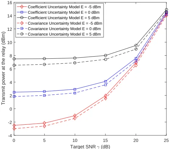
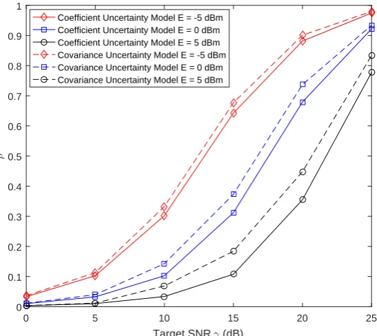
3.2 Transmit power at the relay versus the required SNR γ withPs=5 dBm, ε2=0.1. . . 53
3.3 Optimal PS ratio versus the SNR threshold withγ =5 dB,Ps=5 dBm, and ε2=0.1. . . 54
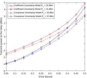
3.4 Relay power versus the error boundεwithγ =5 dB ande=0 dBm . . . . 55
4.1 System model. . . 60
4.2 The relay transmit power w.r.t. iteration numbers for the SPCA algorithm with various Ps. SetR=1.5 bps/Hz,ε =0.01 andη =−5 dBm. . . 81
4.3 Transmit power at the relay versus the target rateR. Setε=0.01 andη=−5 dBm. . . 82
4.4 Transmit power at the relay versus the EH thresholdη. Setε=0.01 and R=1.5 bps/Hz. . . 83
4.5 Transmit power at the relay versus the channel uncertainty level ε. Set R=1.5 bps/Hz andη =−5 dBm. . . 84
4.6 Transmit power at the relay versus the number of eavesdropper K. Set R=1.5 bps/Hz,ε =0.01 andη =−5 dBm. . . 84
5.1 System model. . . 87
5.2 The secrecy rate of the different methods versus the transmit power for different outage probability ρ based on the PCU model with I=−2 dB, σ2=0.005. . . 102
5.3 The secrecy rate versus error varianceσ2for the different interference power based on the PCU model withρ=0.01,P=6 dB. . . 103
5.4 The secrecy rate of the different methods versus the transmit power for different outage probability ρ based on the FCU model with I=−2 dB, σ2=0.005. . . 104
List of figures xi
6.1 An illustration for the considered secure SWIPT scenario. . . 108 6.2 Convergence rate of the AO algorithm for the three safe approximation
List of tables
6.1 Complexity analysis of the AO algorithm based on proposed approaches under PCU model . . . 130 6.2 Complexity analysis of bisection method based on proposed approaches
List of Abbreviations
1-D One-Dimensional 5G The Fifth Generation AC Alternating Current
ADC Analog-to-Digital Converter AF Amplify-and-Forward AN Artificial Noise
AO Alternating Optimization AWGN Additive White Gaussian Noise BER Bit Error Rate
BS Base Stations
BTI Bernstein-Type Inequality
CDF Cumulative Distribution Function CR Cognitive Radio
CSCG Circularly Symmetric Complex Gaussian CSI Channel State Information
D2D Device-to-Device DC Direct Current DF Decode-and-Forward DPS Dynamic Power Splitting DR Desired Receiver
xiv
EM Electromagnetic ER Energy Receiver
EVD Eigenvalue Decomposition FCU Full Channel Uncertainty
FD Full Duplex
HD Half Duplex
ID Information Decoding IR Information Receiver
JBPS Joint Beamforming and Power Splitting KKT Karush-Kuhn-Tucker
LDI Large Deviation Inequality LHS Left Hand Side
LMI Linear Matrix Inequality LP Linear Program
LPF Low-Pass Filter mmWave Millimetre Wave
MIMO Multiple-Input Multiple-Output MRT Maximum Ratio Transmission MISO Multiple-Input Single-Output
OC-SRM Outage-Constrained Secrecy Rate Maximization OFDM Orthogonal Frequency Division Multiplexing OSTBC Orthogonal Space-Time Block Code
PCU Partial Channel Uncertainty PHY Physical Layer
xv
PSD Positive semidefinite
PU Primary User
PSR PS-based Relaying
QCQP Quadratically Constrained Quadratic Program QoS Quality of Service
QP Quadratic Program
R-E Rate-Energy
RF Radio Frequency
RHS Right Hand Side SDP Semidefinite Program SDR Semidefinite Relaxation SEE Secrecy Energy Efficiency SER Secondary Energy Receiver
SINR Signal-to-Interference-Plus-Noise Ratio SIR Secondary Information Receiver
SNR Signal-to-Noise Ratio SOC Second-Order Cone
SOCP Second-Order Cone Program
SPCA Sequential Parametric Convex Approximation SSE Secrecy Spectral Efficiency
ST Secondary Transmitter
SWIPT Simultaneous Wireless Information and Power Transfer
TS Time Switching
TSR TS-based Relaying WPT Wireless Power Transfer WIT Wireless Information Transfer
List of Mathematical Notations
0 All-Zero matrix with appropriate dimension I Identity matrix with appropriate dimension
a ais vector
A Ais matrice
(·)H Hermitian transpose (·)T Transpose
(·)−1 Inverse
Tr(·) Trace operator
R{·} Real part
I{·} Imaginary part
vec(·) Vectorization of matrix
L(·) Lagrange dual function λmax(·) Maximum eigenvalue
E{·} Statistical expectation
| · | Magnitude of a complex number
Diag(·) Diagonal matrix
|A| Determinant of matrixA
∥ · ∥F Frobenius norm
∥ · ∥2 Euclidean norm
[x]+ max(x,0)
⊗ Kronecker products
xvii
Pr{·} Probability functions dom f Domain of a function f
CN(µ,Σ) Complex Gaussian distribution with meanµ and covariance
Σ
Cx×y Set of complexx×ymatrices
Hn Set ofn×ncomplex Hermitian matrices Hn+ Set ofn×npositive semidefinite matrices R Set of real numbers
Rn Set of realn-vertors Rn×m Set of realn×mmatrices
Chapter 1
Introduction
In the last decade, wireless communication technologies have grown dramatically to satisfy the escalating data rate and ubiquitous wireless services. The unprecedented increase of wireless devices leads to the sharp growth of energy consumption. However, the lifetime of the wireless devices is restricted by their finite battery capacity. Although battery replacemen-t/recharging can prolong the lifetime of the wireless devices, this solution is inconvenient and costly in the practical implementation due to the unpredictable environmental change and a large number of devices. Hence, efficiently prolonging the operation time of the devices is significant for the design of next generation wireless communication networks.
1.1 Overview of Wireless Power Transfer 2
1.1
Overview of Wireless Power Transfer
Wireless power transfer (WPT) is a advanced technology that enables to transmit electromag-netic energy from a power source to a device without interconnecting cords. The idea of this technology has been around since hundreds years ago. In the late 19th century, Nikola Tesla conducted several experiments to transfer electromagnetic (EM) power based on microwave technology. Although these experiments were failed due to the limitations of the devices and the technology, Tesla had profound influence on later development of WPT technology.
1.2 Motivations 3
1.2
Motivations
Since RF signals are capable to carry not only energy but also information at the same time, simultaneous wireless information and power transfer (SWIPT) has been recognized as a promising candidate for future 5G systems. However, there exist three key challenges to apply SWIPT in practical communication scenarios. In the following, these challenges are discussed from the aspects of security issues, channel models, and structure of energy receivers (ERs).
• Security Issue. In SWIPT systems, the transmitted information is easily eavesdropped by malicious eavesdroppers due to the broadcast nature of the wireless medium. On the other hand, ERs are generally deployed closer to transmitters to receive higher power compared to information receivers (IRs) since IRs and ERs operate with different power sensitivities in practice. Due to the distribution of these two receivers, ERs might eavesdrop the information instead of harvesting energy based on better channel conditions. Therefore, designing a proper resource allocation strategy to enhance security in SWIPT systems need more research efforts in general.
1.3 Contributions and Thesis Organization 4
to the perfect CSI model, it is more interesting to investigate the application of SWIPT under the imperfect CSI model.
• Non-linear ER.In a linear EH model, the RF-to-direct current (DC) power conversion efficiency is independent to the RF power available received at EH circuits. However, the use of the linear EH model in practice might cause resource allocation mismatches and performance degradations since the relationship between the inputs and the outputs of the EH circuits is highly non-linear. Therefore, it is more interesting to investigate system performance in non-linear EH model.
1.3
Contributions and Thesis Organization
1.3.1
Contributions
Motivated by the above discussions, this thesis focus on the applications of SWIPT in modern wireless communication networks to three aspects: channel estimations, security issues, and receiver designs. More particularly, SWIPT technique is first applied to a multiuser cooperative network to investigate the system performance. Then, security issue of SWIPT system is investigated in cooperative networks and cognitive radio (CR) networks. In the last, the impact of the non-linear EH model on the system security is investigated. The contributions of this dissertation are summarized in the following.
1.3 Contributions and Thesis Organization 5
relay beamforming vectors and PS ratios are jointly designed to minimize the relay transmit power while satisfying the quality of service (QoS) and the EH constraint of each receiver. In order to solve the optimization problem, the semidefinite relaxation (SDR) method and the Lagrangian duality method are adopted to relax the original problem to the tractable convex problem. Besides, a rank-one proof presents that the solution generated by the relaxed problem is optimal to the original problem. Finally, the performances of the robust schemes are evaluated by simulations.
In chapter 3, a secure information transmission is investigated in a multi-antenna AF relay network in the presence of potential eavesdroppers based on the assumptions of perfect and imperfect CSI. In the considered scenario, a PS receiver architecture is employed at a desired receiver (DR) to harvest energy from the information bearing signal. A power minimization (PM) problem is designed by jointly optimizing the secure beamforming vector and the PS ratio to satisfy the constraint requirements of the secrecy rate and the harvested energy. Since the nonconvexity of the PM problem is arising from the quadratic terms and the coupled variables, the one-dimensional (1-D) linear search and the SDR method are employed to obtain the solutions. Furthermore, a rank reduction algorithm is proposed to guarantee that the optimal solution of the problem is achieved. On the other hand, a low complexity iterative algorithm based on the sequential parametric convex approximation (SPCA), is proposed to obtain the suboptimal solutions. In addition, the S-procedure method is employed to convert the semi-infinite constraints into linear matrix inequalities (LMIs) in the imperfect CSI case.
1.3 Contributions and Thesis Organization 6
the secondary receiver, harvested energy at the secondary ER, and the maximum interference at the PU. Since there is no closed-form expression for the probabilistic constraint, the Bernstein-type inequality (BTI) approach is employed to convert the probabilistic constraints into the deterministic constraints. The tractable solution of the proposed problem can be obtained by alternately solving two convex conic subproblems. Furthermore, the same robust design is considered in the full Gaussian CSI uncertainty case. Finally, the effectiveness of the proposed algorithm is validated by simulations.
1.4 Publication List 7
1.3.2
Thesis Outline
The remainder of this thesis is organized as following. Chapter 2 introduces some funda-mental concepts and reviews literature relevant to this thesis, e.g. basic principles of RF energy transfer, SWIPT, CR, cooperative communication, physical layer security, and convex optimization technique. Chapter 3 investigates beamforming and receiver design in SWIPT assisted cooperative networks. Chapter 4 studies the application of SWIPT in cooperative networks by considering security issue. Chapter 5 investigates the impact of security on SWIPT in underlay CR networks. Chapter 6 presents the secure communication in downlink MIMO-SWIPT networks with non-linear ERs. Chapter 7 draws the conclusions of this thesis and discusses the promising future research directions.
1.4
Publication List
• Journal Papers
1. Y. YUANand Z. Ding, “Robust Outage Constrained Design for Secrecy MIMO-SWIPT Systems Based on a Non-linear EH Model,” IEEE Transactions on Vehicular Technology (under preparation).
2. Y. YUAN, Z. Ding, Mai Xu, and Ningning Qin, “Secure Beamforming and Power Splitting Designs in Multi-antenna AF Relay Networks,” submitted toIET Communications (In review).
1.4 Publication List 8
4. G Pan, H Lei,Y Yuan, and Z Ding, “Performance analysis and optimization for SWIPT wireless sensor networks,”IEEE Transactions on Communications, vol. 65, no. 5, pp. 2291-2302, May 2017.
5. P Xu,Y Yuan, Z Ding, X Dai, and R Schober, “On the Outage Performance of Non-Orthogonal Multiple Access With 1-bit Feedback,”IEEE Transactions on Wireless Communications, vol. 15, no. 10, pp. 6716-6730, Jul. 2016.
• Conference Papers
1. Y Yuanand Z. Ding, “Secrecy Outage Design in MIMO-SWIPT Systems Based on a Non-linear EH Model”, inProc. IEEE Proc. IEEE Globecom Workshops, Singapore, December 2017.
2. Y Yuanand Z. Ding, “The application of non-orthogonal multiple access in wire-less powered communication networks”,in 17th IEEE International Workshop on Signal Processing Advances in Wireless Communications (SPAWC), Edinburgh, July 2016.
3. S. Hu, Z. Ding, Q. Ni, and Y. Y. Yuan, “Beamforming optimization for full-duplex cooperative cognitive radio networks”,in 17th IEEE International Work-shop on Signal Processing Advances in Wireless Communications (SPAWC), Edinburgh, July 2016.
1.4 Publication List 9
Chapter 2
Fundamental Concepts and Literature
Re-view
2.1
Fundamental Concepts
2.1.1
RF Energy Transfer
2.1 Fundamental Concepts 11
tower, which is 4.1 km away and uses 960 kW transmission power. Typically, the amount of harvested energy is in order of micro-watts, which is sufficient for powering small devices [15].
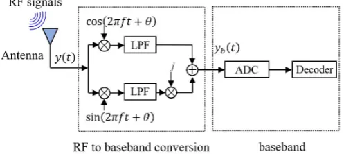
[image:28.595.177.426.267.378.2]In RF-WPT systems, RF signals is broadcasted to the distributed users from the BS or the energy transmitter. Generally, energy carried by RF signals cannot be harvested by the typical information receiver (shown in Figure 2.1). As shown in Figure 2.1 [16], the received
Fig. 2.1 Architecture for information receiver.
RF signal are first converted to a baseband signal through the processing at two low-pass filters (LPF). Then, the baseband signal is converted to a digital signal by analog-to-digital converter (ADC) before decoding.
In order to enable EH, typical ERs are added in distributed users. According to the design of the RF energy receiver in [5], the architecture of the typical RF energy receiver is depicted in Figure 2.2. As depicted in Figure 2.2, a typical ER includes a antenna system, an independent
Fig. 2.2 Architecture for energy receiver.
2.1 Fundamental Concepts 12
received antenna can be designed to work on a single or multiple frequency bands. The aim of the independence matching part is to maximize the power transfer between the antenna and the rectifier by using a resonator circuit. The designed frequency is capable to enhance the matching efficiency at the resonator. The rectifier including diodes and LPF is an important part for ERs, because the input RF signals (alternating current (AC) type) captured by the antenna can be converted into DC voltage by using diodes and LPF. Finally, the DC voltage can either power the load directly or charge energy storage. Note that the lower turn-on voltage at the diodes can provide higher conversion efficiency. The reason is that diodes will not work until the received power at the energy harvester is greater than its turn-on voltage. If the received power at the energy harvester cannot overcome this barrier, the conversion efficiency will be zero. In addition, the capacitor at the rectifying circuit not only smoothly delivers power to the load but also supplies energy for a short time when RF energy is unavailable. Typically, a RF signal with frequency rang between 3kHz to 300GHz can be utilized as a medium to carry energy. The RF-to-DC conversion efficiency is mainly dependent on three parts: the captured power density at the receiver antenna, the accuracy of the independence matching and the power efficiency of the rectifier [17]. Due to the benefits of the far-field RF propagation model, the energy transfer based RF signals has clearly advantages of powering a large number of terminals in a wide area [6, 15, 18]. Therefore, this thesis focus on RF energy transfer technique to enable EH.
2.1 Fundamental Concepts 13
signal power can be expressed as following by exploiting the Friis equation [19]
PEH =PTGTGRλ
2
(4πd)2L, (2.1)
wherePEH denotes the received energy,PT is the transmit power,GT andGRrepresent the transmit antenna gain and the receiver antenna gain,λ is the wavelength,d is the distance between the transmit antenna and the receiver antenna, andLdenotes the path loss factor.
Equation (2.1) provides an ideal model for the received signal power based on the no reflection path assumption. However, in practical scenario, scattering and reflection exist between the transmitter and the receiver. The scattering and reflection may cause that the received signal at the receiver comes from multiple path. In this situation, the equation (2.1) cannot be used to compute the received signal power. Therefore, a more general two-ray ground reflection model, which includes a line-of-sight path and a ground reflection path, is considered to compute the received signal power [20]. The received signal power according to the two-ray ground model is given by [15]
PEH=PTGTGRh
2
th2r
d4L , (2.2)
whereht andhr denote the heights of the transmit and receive antennas, respectively. Note
that the wavelength is eliminated by calculation. More details can be found in [20].
2.1.2
Simultaneous Wireless Information and Power Transfer
2.1 Fundamental Concepts 14
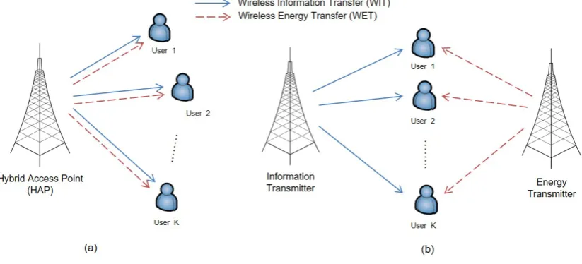
[image:31.595.103.515.194.381.2]categories, integrated-SWIPT (shown in Figure 2.1 (a)) and decoupled-SWIPT (shown in Figure 2.1 (b)), based on whether the received signal at the receiver comes from the same BS. In integrated-SWIPT scenarios, the energy signal and the information signal are both carried
Fig. 2.3 Architecture for SWIPT systems.
in the same RF signal. In decoupled-SWIPT scenarios, the information signal and the energy signal, generated by the different BS, are received at the receiver at the same time. This model can overcome the limitation of integrated-SWIPT model, because of receivers can be deployed close to the energy transmitter. However, this model causes serious interference at the receiver side.
2.1 Fundamental Concepts 15
based on the assumption of the ideal receiver architecture, which means that receivers in both studies are capable to decode information and harvest energy from the same received signal at the same time. However, this assumption is difficult to implement in practical systems because practical circuits are totally different for ID and EH [23, 24]. In other words, the transmitted information cannot be decoded at the ideal receiver during the EH processing. Inspired by this challenge, three types of receiver architectures are designed to implement SWIPT in wireless communication networks in the current thesis. In the following parts, these practical receiver designs are introduced, namely separated receiver architecture, co-located receiver architecture and integrated receiver architecture.
2.1.2.1 Separated Receiver Architecture
Zhang et al. proposed a separated receiver architecture to simultaneously implement ID and EH at the receiver side. In this practical architecture, the EH circuit and the ID circuit are adopted in two independent receivers, respectively [23]. These two types of receivers can be easily built based on off-the-shelf information receivers and energy receivers. Moreover, the trade-off between the achievable information rate and the harvested energy can be obtained by using optimization techniques.
2.1.2.2 Co-located Receiver Architecture
2.1 Fundamental Concepts 16
[23] proposed two practical receiver models, namely time switching (TS) receiver and power splitting (PS) receiver, to overcome the practical limitation of the co-located receiver design. In the following, these two practical receivers are introduced in orders.
1. Time Switching Receiver. An information receiver and a RF energy receiver are connected to the same antenna in the TS receiver. In this scheme, the transmission block is divided into two orthogonal time slots at the transmitter, i.e., one for information transmission and the other for energy transfer. Based on a time switching sequence, each antenna is capable to switch the received signal to the EH circuit or the ID circuit in two time slots [23]. The perfect time synchronization between the receiver and the transmitter is important to implement SWIPT in the TS receiver. The optimal R-E trade-off can be achieved by optimizing the time switching sequence.
2. Power Splitting Receiver. A passive power splitter is equipped at each antenna to distribute the received signal to the EH circuit and the ID circuit based on different power levels. In fact, the received signal is split into two signal streams with different power. One stream with 0≤ρ ≤1 portion signal power is used for ID, and the other stream is used for EH with 1−ρ power [23, 24]. The different trade-off between the achievable information rate and the harvested energy can be achieved by using different PS ratioρ. When ratioρ =0 orρ =1, the PS receiver becomes as the TS receiver.
2.1.2.3 Integrated Receiver Architecture
2.1 Fundamental Concepts 17
the baseband signal for information decoding. Therefore, the IR at the integrated receiver does not need any RF band to baseband conversions.
2.1.3
Physical Layer Security
Information security has been considered as one of the most essential issues in wireless communication systems as broadcast characteristics of wireless medium cause that con-fidential messages are susceptible serious eavesdropping threats from unauthorized users. With continuous research of secure communications, cryptography has been considered as a traditional high-layer encryption technique to circumvent the occurrence of the information eavesdropping [25]. However, traditional cryptographic techniques may have defects since the operations of these techniques are based on the assumption of the limited computational capability of the eavesdroppers [26, 27]. Additionally, the perfect key distribution and man-agement may not always be available when establish secure communication links by using cryptographic techniques [28].
2.1 Fundamental Concepts 18
capacity. Therefore, the perfect secrecy capacity can be given by [30]
Is= [IM−IE]+, (2.3)
whereIM and IE denote the capacity of the main channel and the eavesdropper channel, respectively. The method to achieve the perfect secrecy communication in the wiretap channel has attracted more attention. Two approaches are considered to ensure the perfect secure communication. One is to improve the received signal power at the legitimate receiver, that is the legitimate receiver is distributed closer to the source than the eavesdropper. However, this approach is not easy to implement in practice due to the silent features of eavesdroppers. The other one is to impair the received signal quality at the eavesdropper. Jamming signals [31] and AN signals [32] can be utilized to impair the received signal at the eavesdroppers.
2.1.4
Cooperative Networks
2.1 Fundamental Concepts 19
virtual antenna array and a multi-path transmission can be constructed. As a consequence, the cooperative technique can offer important enhancement in terms of energy and spectrum efficiency, network connectivity, and communication reliability [37].
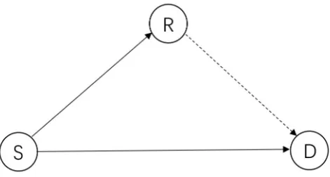
[image:36.595.187.423.291.417.2]In cooperative communication networks, each terminal performs two roles-a source node to transmit information and a relay node to help information transmission. A classic three-node cooperative system is shown in Figure 2.4 to illustrate the communication procedure. In this system, there exist two different communication channels - a direct transmission
Fig. 2.4 A classic three-node cooperative system.
2.1 Fundamental Concepts 20
The AF protocol - the simplest relay protocols - was first proposed and analyzed by Laneman
et al. [38]. In the AF relay system, the relay node forwards the amplified information and noise to the destination node. This protocol is suitable for the relay node with the limited power. The DF protocol is another simple cooperative signaling method, which was proposed in [39, 40]. In the DF relay system, the relay node decodes the received signals and re-encodes them before forwarding to the destination. The protocol may cause higher bit error rate (BER) compared with the AF protocol.
2.1.5
Cognitive Radio Networks
CR technology was first developed by Mitola to establish dynamic spectrum access (DSA) networks [41]. It has been considered as a promising technology to alleviate the spectrum scarcity issue, which is caused by the rapid explosion of wireless devices and the inefficient usage of the existing spectrum, by utilizing the network resources in a more efficient and intelligent way. Different from traditional communication paradigms, CR technology is capable for unlicensed users to access the licensed spectrum intelligently according to the variations of the surrounding environment [42].
Based on the three existing paradigms of the CR network, namely, interweave, overlay, and underlay, secondary users are capable to efficiently utilize the spectrum resources [43]. These three paradigms are categorized according to different interference management strategies. A brief description of these three paradigms is provided as follows.
2.1 Fundamental Concepts 21
communication of the secondary system does not interfere the existing communication of the primary system. In other words, the concurrent communications of the secondary system and the primary system are not allowed in the interweave CR network.
2) Overlay Paradigm. The overlay paradigm refers to an interference mitigating technique by exploiting sophisticated signal processing and coding. The key idea of enabling overlay CR is that the codebooks and the messages of the primary system are well known at the secondary transmitters. By exploiting this knowledge, the secondary transmitters not only completely cancel the interference of the primary system to the secondary receivers but also can be used as relays to assist the information transmission of primary system. Therefore, in overlay CR systems, the communication rate of the primary system is capable to remain unchanged while the secondary system is capable to obtain additional bandwidth for its own communication [43].
3) Underlay Paradigm. The underlay paradigm allows concurrent communications of the secondary system and the primary system by intelligently controlling the interference caused by the secondary system to the primary system. Specifically, the secondary system is permitted to transmit its information on the spectrum allocated to the primary system only if the interference generated by the secondary system is below the accept-able constraint [46]. The availaccept-able transmission power of the secondary transmitter is limited due to the restrictive interference control in underlay CR systems. As the interference caused by the secondary system is rigorously controlled in underlay CR systems, the available transmission power of the secondary system is restricted. In other words, the secondary system is only suitable for short-range communication in underlay CR systems.
2.2 A Brief Literature Review of SWIPT Application 22
can be employed in many wireless communication scenarios to improve the usage efficiency of bandwidth.
2.2
A Brief Literature Review of SWIPT Application
Recently, SWIPT has been considered as a promising technology to solve the energy scarcity problem in energy-constrained wireless networks as RF signals not only carry information but also transfer energy. Motivated by this, SWIPT technique has been widely applied for academic research and industry applications. In the following subsections, the related works of this thesis surrounding SWIPT are discussed in different wireless communication networks.
2.2.1
SWIPT in Single-Hop Systems
SWIPT technique was applied in single antenna scenarios [24, 47–50] and multi-antenna scenarios [23, 51–59].
2.2.1.1 SWIPT in Single-Antenna Systems
2.2 A Brief Literature Review of SWIPT Application 23
tolerant scenarios and the optimal outage-energy tradeoff for delay-limited scenarios were studied with and without CSI at transmitters in [47] and [48], respectively. Compared with the TS policy proposed in [47], the PS policy proposed in [48] not only gains higher information gain but also harvests more energy. SWIPT technique was also applied in the orthogonal frequency division multiplexing (OFDM) system to coordinate EH and ID operation [49, 50]. The authors in [49] design the resource allocation, the sub-carrier allocation and the PS ratio in a multiuser single-antenna OFDM system in which each receiver employed a power splitter to split the received RF signal. Since the work in [49] was based on the assumption that the PS ratio is different for each subcarrier, a practical OFDM-based SWIPT system with the same PS ratio for all subcarriers was proposed in [50].
2.2.1.2 SWIPT in Multi-Antenna Systems
The practical circuit limitation at the receiver has been overcome in the single antenna system. There still exists another challenge caused by the energy transfer efficiency that needs to be considered when designing WPT systems. In wireless communication systems, the energy transfer efficiency decreases along with the increase of the transmission distance since energy carried by RF signals is more sensitive to the propagation path loss. This drawback is especially severe in single-antenna systems, because the RF signal generated by a single-antenna transmitter has omni-directional radiation characteristic. Multi-antenna techniques have been deemed as an appealing solution to improve efficiency of RF energy transfer. The reason is multi-antenna techniques not only achieve spatial multiplexing but also employ beamforming technique, which is capable to achieve directional transmission, without requiring additional bandwidth and transmit power. Therefore, multi-antenna techniques have been employed to transmit the RF signals toward the target receivers [23, 51–59].
2.2 A Brief Literature Review of SWIPT Application 24
at the transmitter, the authors investigated the optimal precoding matrix and transmission strategies to achieve the rate-energy trade-off in either the separated or the co-located ID and EH receiver. It is worth pointing out that the authors proposed two receiving strategies, which allocates the received signal at the co-located receiver to ID circuit and EH circuit from a time and power perspective. Inspired by [23], the authors in [51] extended [23] to a three-node multiple-input single-output (MISO) system under the imperfect CSI assumption. In this work, the transmit beamforming was optimized under the worst-case model to enhance the harvested energy at the ER while satisfying the rate requirement at the IR. The authors also provided the theoretical proof to guarantee the relaxation is always tight. The studies for SWIPT that consider the multiple information receivers and energy receivers were investigated in a MISO downlink broadcast system based on the perfect CSI assumption [54] and the imperfect CSI assumption [55]. In [54], the two types of information receivers that are with and without the capability of canceling the interference were considered. For each type of the information receiver, the authors aimed to jointly design beamforming and power allocation to obtain the maximum weighted sum harvest energy while guaranteeing the signal-to-interference-plus-noise ratio (SINR) requirement of each information receiver. Two approaches (based on the SDR and the uplink-downlink duality) were proposed to solve the non-convex problems for both types of information receivers. In [55], the worst harvested energy maximization problem was proposed to design robust beamforming based on the SINR constraint and the total transmit power constraint. An iterative algorithm based on the bisection method was proposed to solve the problem and obtain the robust solution.
2.2 A Brief Literature Review of SWIPT Application 25
single operation modes, the achievable rate and the harvested energy could be maximized by the information rate maximization problem and the harvested energy maximization problem, respectively. For the different operation mode, the achievable rate-energy region was investigated based on the two rank-one beamforming strategies. Then, the problem investigated in [52] was generalized toktransmitter-receiver pairs [53].
2.2 A Brief Literature Review of SWIPT Application 26
2.2.2
SWIPT in Cooperative Networks
Although cooperative techniques are able to overcome fading and attenuation for long distance communication by using relay nodes, the activity of relay nodes may be restricted by limited battery. Therefore, the EH technique is adopted to extend the lifetime of wireless nodes in cooperative networks [60, 61]. Cooperative networks with the EH technique not only increase the transmission efficiency and reliability but also maintain the activity of networks. Based on the advantage of the EH technique, the applications of this technique have been investigated in single relaying networks [62–69] and multiple relaying networks [70–74].
RF Energy transfer was first applied in an orthogonal space-time block codes (OSTBC) MIMO relay system to design the optimal source and relay precoding with discharged relay [62]. Then, the authors in [63, 64] extended works in [62] by considering the charging relay. In [63], a simple greedy switching policy, which was designed based on the idea of TS scheme, was proposed to intelligently switch the operation mode of the relay node. Specifically, the relay node is capable to decide when to harvest energy and when to forward information based on the proposed policy. By using Markov chain, the closed-form expression of outage probability was obtained to evaluate the system performance. In [64], a dynamic antenna switching policy, which is capable to allocate a certain number of antennas for the ID operation and remaining antennas for the EH operation, was proposed in a MIMO relay system by exploiting the array configuration.
2.2 A Brief Literature Review of SWIPT Application 27
respectively. It is worth noting that the throughput of the TSR protocol is better than the PSR protocol at the relatively low signal-to-noise ratio (SNR) and high transmission rates based on the results in [65]. Then, the same authors proposed adaptive TS protocols for two different modes of EH: EH with continuous time and EH with discrete time [66]. The authors found out that the proposed protocols in [66] outperformed the TSR protocol in [65] through comparing the simulation results. In [68], the authors investigated the system performance of a three-node DF relay network with and without direct link by exploiting two relaying protocols in [66]. With the analysis for the considered system, the authors pointed that the optimal coefficient for both protocols depended on the channel conditions and the remaining energy of the relay node. By adopting the DF relaying strategy, energy distribution strategies on the relay were proposed to investigate the impact of different strategies on the system performance [67]. With the same relaying strategy, the transmission rate for the cases with and without direct link were investigated in [68]. The authors in [69] studied the impact of SWIPT on the end-to-end achievable data rate in a two-hop non-regenerative MIMO-OFDM relay system.
2.2 A Brief Literature Review of SWIPT Application 28
2.2.3
SWIPT in Cognitive Radio Networks
2.3 A Brief Literature Review of Security Issues in SWIPT Systems 29
2.3
A Brief Literature Review of Security Issues in SWIPT
Systems
In SWIPT systems, the transmitter may need to amplify the power of the transmitted signal in order to satisfy the EH requirement which may cause more information leakage. In addition, ERs are normally deployed closer to the transmitter compared with IRs, because the IR and the ER work on different power sensitivities, e.g., -60 dBm for IRs versus -10 dBm for ERs [23]. These two factors raise a new security issue for SWIPT systems since the information sent to the designed receiver is vulnerable to be attacked by unexpected eavesdroppers or ERs. Therefore, it is desirable to implement some methods to avoid unexpected eavesdroppers and ERs from recovering the confidential message from their observations. Based on the PHY security technology, a very limited number of research papers have considered the secure communication in single-hop networks [81–88], cooperative networks [89–96] and cognitive networks [97–100].
2.3.1
Security Issues in Single-hop Networks with SWIPT
2.3 A Brief Literature Review of Security Issues in SWIPT Systems 30
However, perfect CSI for all receivers is not easy to be obtained by the transmitter due to the existence of channel estimation errors and quantization errors in the practical scenarios. Thus, it is important to design a secure communication strategy under the imperfect CSI condition. A very limited number of research papers had designed robust secure communication strate-gies in SWIPT systems based on the bounded CSI error model [83–86] and the probabilistic CSI error model [87, 88]. In [83], the authors utilized the AN and energy signals to provide the secure communication and efficient WPT in the presence of passive eavesdroppers and potential eavesdroppers (idle legitimate receivers). A robust secure beamforming algorithm was investigated in the MISO-SWIPT system and the MIMO-SWIPT system through the se-crecy rate maximization design [84] and the worst-case sese-crecy rate design [85], respectively. In [86], a two-step algorithm was proposed to circumvent the rank-one solution in the MISO secure SWIPT system. In addition, a novel SDP relaxation was investigated to guarantee that the relaxed problem yielded rank-one solution. Compared with the bounded CSI error model in [83–86], the probabilistic CSI error model was more suitable to the delay-sensitive communication scenario. In [87], the authors proposed an outage-constrained robust method to design transmit beamforming while satisfying the probability constraints of the secrecy rate and the harvested energy. Then, the work in [87] was extended to the MIMO scenario [88].
2.3.2
Security Issues in Cooperative Networks with SWIPT
2.3 A Brief Literature Review of Security Issues in SWIPT Systems 31
relay transmit power and the maximum harvested energy was investigated to design a secure relay beamforming in a nonregenerative multi-antenna relay network in the presence of an eavesdropper. In [92], multiple wireless EH-enabled friendly jammers were used to improve the information security in a multi-antenna AF relay network. Specifically, the authors in [92] jointly designed the AN covariance and relay beamforming by investigating the secrecy rate maximization problem based on the assumption of perfect CSI and imperfect CSI at the relay. In [93], a novel multi-antenna AF relay network was proposed to simultaneously prolong the operation time of the relay and disturb the information at the eavesdropper by using energy signals provided by the destination node. While in [93], the authors investigated the impacts of the massive MIMO relay on the information security and the power transfer efficiency in very adverse environments. The analysis results indicated that the power transfer efficiency could be significantly enhanced by the characteristic of the large array gain, and the information security could be improved by utilizing the high-resolution spatial beamformer. Furthermore, cooperative beamforming and energy signal were jointly designed by solving the proposed optimization problem in an AF relay network [95]. Recently, the authors in [96] proposed a secrecy rate maximization problem under the source and the relay transmit power constraints as well as the EH constraint at each ER to jointly design the source and relay beamforming matrices.
2.3.3
Secure Issues in Cognitive Radio Networks with SWIPT
2.4 Convex Optimization Theory 32
(SER). The authors in [98] proposed a multi-objective optimization framework to investigate the information security of the secondary system in a multiuser CR network with SWIPT. A Pareto-optimal resource allocation algorithm was designed to enhance the information security of the secondary system by jointly minimizing the total transmit power and the interference-power-leakage-to-transmit-power ratio as well as maximizing the EH efficiency. While in [99], the secrecy outage probability was investigated in a CR network based SWIPT. Recently, Zhou et al. studied the secure communication in a MISO downlink CR network where a secondary transmitter simultaneously transferred the information and power to cognitive receivers [100]. The optimal and suboptimal secure beamforming was designed to enhance the security of the secondary system in the bounded CSI error model and the probabilistic CSI error mode, respectively [100].
2.4
Convex Optimization Theory
2.4 Convex Optimization Theory 33
2.4.1
Convex Set
A setSis considered to be a convex set if there exists anyx,y∈Sand anyθ with 0≤θ ≤1 satisfy the following condition
θx+ (1−θ)y∈S. (2.4)
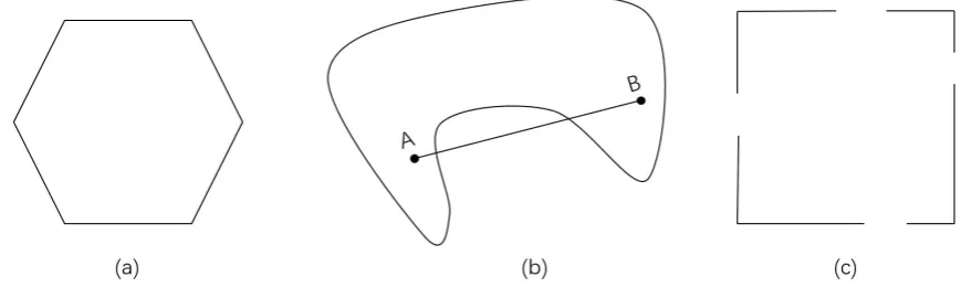
[image:50.595.85.520.415.550.2]The condition (2.4) means that a set can be defined as a convex set if this set is continuous and every points in the set can be seen by each other without any obstacles. In other words, the line segment between any two points in a convex set is lying in this set [101]. Based on the definition of convex set, we know that every affine set is convex set since the entire line between any two distinct points is included in the affine set. Figure 2.5 shows the examples about the convex and non-convex sets [101]. It obviously indicates that (a) is convex set
Fig. 2.5 Convex set (a) and non-convex sets (b), (c).
since (a) is hexagon with continuous boundary. Figure 2.5 (b) is the non-convex set since the line segment between point A and point B is not lying the graphic. Also, Figure 2.5 (c) is non-convex set due to the discontinuous boundary.
2.4 Convex Optimization Theory 34
definition (2.4). In other words, a set can be called convex cone if this set is convex and cone. The concept of convex set has been introduced in this subsection. This is the first step to understand the concepts of convex optimization. In the next subsection, we will introduce convex function, which is an important part for understanding convex optimization.
2.4.2
Convex Function
Similar to the convex set introduced in the above subsection, convex function is also an important step to define convex optimization problem. The concepts of convex function and how to define a function whether is convex or not is presented in the ensuing part.
2.4.2.1 Fundamental Definition of Convex Function
If the domain of a function f is convex set and for allx, y∈dom f as well as 0≤θ ≤1 satisfy the following inequality
f(θx+ (1−θ)y)≤θ f(x) + (1−θ)f(y), (2.5)
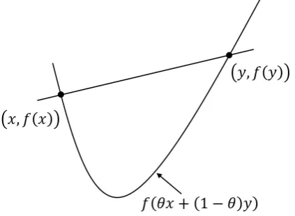
this function f can be defined as a convex function [101]. Geometrically, the definition of the convex function f means that the graph of f(θx+ (1−θ)y)lies below the line segment between(x,f(x))to (y,f(y))[101]. In other words, the graph of a convex function looks like a faceup bowl as illustrated in Figure 2.6 [101]. If strict inequality holds in (2.5) when
x̸=yand 0<θ <1, the function f is defined asstrictly convex. Then, if function f is said to be concave if−f is convex.
2.4 Convex Optimization Theory 35
Fig. 2.6 Graph of a convex function.
function. To verify the convexity of a function based on the definition is a general way, we introduce two powerful conditions to verify the convexity for differentiable functions in the ensuing parts.
2.4.2.2 First-order Condition
We assume that f is a first order differentiable function which means that the gradient of f
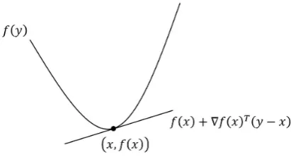
exists at each point in its domain. Then, f is convex function if and only if its domain is convex set and it satisfies the following inequality condition
f(y)≥ f(x) +∇f(x)T(y−x), x,y∈domf. (2.6)
2.4 Convex Optimization Theory 36
Fig. 2.7 First-order condition for a convex function f.
2.4.2.3 Second-order Condition
Suppose that f is a twice differentiable function. Then, we can define that function f is convex if and only if its domain is convex and its Hessian matrix is positive semidefinite (PSD), which can be written as follows:
∇2f(x) =
∂2f(x) ∂xi∂xj
m×m
≽0, ∀x∈Rm. (2.7)
According to the second-order condition, a quadratic function f(x) =xHAx+bTx+c is convex if and only ifA≽0.
2.4.3
Convex Optimization Problems
2.4 Convex Optimization Theory 37
general, a standard optimization problem can be expressed as
min f0(x)
s.t. fi(x)≤0, i=1, . . . ,m,
hi(x) =0, i=1, . . . ,p, (2.8)
wherex∈Rnis the optimization variable; f
0(x)denotes the objective function; fi(x)and
hi(x)are inequality constraints and equality constraints, respectively. The problem domain of (2.8) can be defined as
D=
( m
\
i=0
dom fi
)
\
( p
\
i=1
domhi
)
. (2.9)
If a pointx∈D satisfies all constraints in problem (2.8), then this point is called feasible point of this problem. The set of all feasible points is called the feasible set. The problem (2.8) can be defined as convex optimization problem if its objective function f0(x)is convex
and constraints are convex as well as domain is convex set. An optimization problem is either convex or non-convex once it is formulated. For the naturally convex problem, it can be solved directly.
2.4.3.1 Linear Program
A optimization problem is said to be a linear program (LP) when the objective and all constraint functions are affine. Then, a general linear program can be formulated as
min
x c
Tx+d
s.t. Gx≼h,
2.4 Convex Optimization Theory 38
whereG∈Rm×n, A∈
Rp×n,x, hand bare vector. Note that if inequality constraints in
(2.10) are only componentwise nonnegativity constraints, this problem is calledstandard form LP. If the problem in (2.10) only contains inequality constraints, the problem is said to beinequality form LP. Based on the the definition of convex function in (2.5) and the first-order condition in (2.6), linear programs are said to be convex optimization problems [101]. Note that the maximization of an LP is equivalent to the minimization of this LP since the polarity of the objective function can be reversed.
2.4.3.2 Quadratic program
A optimization problem is called as a quadratic program (QP) if the objective function is quadratic and the constraint functions are affine. The structure of a QP can be given by
min
x x
TPx+qTx+d
s.t. Gx≼h,
Ax=b, (2.11)
whereP∈Sn,G∈
Rm×n,A∈Rp×nandxis a vector. If and only if symmetric matricPis
PSD, QP in (2.11) is convex problem. The key idea of QP is to find the minimum value of a quadratic function over a polyhedral set. LP is a special case of QP by takingP=0.
2.4 Convex Optimization Theory 39
follows:
min
x x
T
P0x+qTx+d
s.t. xTPix+qiTx+di≤0, i=1, . . . ,m,
Ax=b, (2.12)
wherePi∈Sn, i=0,1, . . . ,mandxis a vector.
2.4.3.3 Second-Order Cone Program
In this part, we introduce another convex optimization problem which is related to QP. This problem is called second-order cone program (SOCP), which has the following structure
min
x b
Tx
s.t. ∥Aix+bi∥2≤aTix+di, i=1, . . . ,m,
Gx=g, (2.13)
whereAi∈Rni×nandxis a vector. The inequality constraint in (2.13) is called the
second-order cone constraint. This second-second-order cone constraint means that an affine function aTi x+di is lying in the second-order cone. Some QCQPs can be converted to the SOCPs.
2.4 Convex Optimization Theory 40
2.4.3.4 Semidefinite Program
In this part, anther powerful optimization problem is introduced. The conic form problem can be called as Semidefinite program (SDP), which has the following structure
min
x b
Tx
s.t. x1F1+x2F2+. . .+xnFn+G≼0,
Ax=b, (2.14)
whereG, F1, . . . , Fn∈Sk,x= [x1,x2, . . . ,xn]∈Rnandb∈Rn. It notes that the inequality
in (2.14) is the linear matrix inequality (LMI). If replacingG, F1, . . . , Fnby their diagonal
matrixes, then the LMI in (2.14) is equivalent to a set ofnlinear inequalities, and the SDP (2.14) reduces to a LP.
A briefly description about how to convert QCQP into SDP for the real-variable case is introduced. The complex-variable case can be similarly performed by the real-variable case. First, a relationship between a linear inequality and a LMI is defined. Based on the principle of the inequality transformation, the following convex quadratic inequality
(Ax+b)T(Ax+b)−aTx−c≤0, ∀x∈Rn (2.15)
holds true if and only if the following LMI
I Ax+b
(Ax+b)T aTx+c
≽0, ∀x∈Rn (2.16)
2.4 Convex Optimization Theory 41
Next, an example is provided to prove how to convert QCQP into SDP. Consider the following optimization problem
min
x ∥A0x+b0∥
2
2−cT0x−d0
s.t. ∥Amx+bm∥22−cTmx−dm≤0, m=1, . . . ,n. (2.17)
whereAm∈Rn×nandx, cm, bm∈Rn. According to the definition of the QCQP problem
in (2.12), which consists of quadratic objective function and quadratic constraints, problem (2.17) can be defined as a QCQP problem. The reason is that problem (2.17) includes the quadratic objective function and quadratic constraints. Then, by exploiting epigraph representation, problem (2.17) can be converted to the following problem
min
x,t t
s.t. (A0x+b0)T(A0x+b0)−cT0x−d0≤t
(Amx+bm)T(Amx+bm)−cTmx−dm≤0, m=1, . . . ,n. (2.18)
Based on the relationship between the quadratic inequality (2.15) and the LMI (2.16), it is easily to convert the quadratic inequality constraints in (2.18) into the following LMI constraints
I A0x+b0
(A0x+b0)T cT0x+d0+t
≽0
I Amx+bm
(Amx+bm)T cTmx+dm+t
2.4 Convex Optimization Theory 42
Finally, problem (2.17) can be expressed by the following problem
min
x,t t
s.t. (2.19). (2.20)
Note that problem (2.20) is a SDP problem since the objective function of (2.20) is a linear function and the inequality constraints of (2.20) are LMI constraints. The objective and constraint functions satisfy the definition of SDP problem in (2.14).
2.4.3.5 Duality and KKT Conditions
We consider the standard optimization problem (2.8) and its nonempty domainD in (2.9). We assume that the optimal value of problem (2.8) is p∗. In the following, we consider to use problem (2.8) as an example to introduce the Lagrange duality. The key idea to obtain the Langrange dual function of problem (2.8) is to combine the objective and weighted sum constraint functions into one expression. Then, the Lagrangian function associated with problem (2.8) can be defined as
L(x,λ,ν) = f0(x) +
m
∑
i=1λifi(x) + p
∑
i=1νihi(x), (2.21)
whereλ and ν are the vector ofλi andνi; λi andνiare called dual variable or Lagrange
multiplier associated with the ith inequality constraint fi(x)≤0 and equality constraint
hi(x) =0, respectively. It notes that L(x,λ,ν) is affine function of (λ,ν) with fixed x. Based on the Lagrangian functionL in (2.21), the associated dual function can be defined by minimizing the Lagrangian function overxas follows:
2.4 Convex Optimization Theory 43
with
domg={(λ,ν)|g(λ,ν)>−∞}, (2.23)
where inf(A)denotes the infimum ofA. The dual functiongis always concave in terms ofλ andν regardless of whether the primal problem is convex or not as the dual function is the pointwise infimum of a family of affine functions of(λ,ν)[101].
The dual functiong(λ,ν)is the lower bound of the optimal value p∗of the primal problem (2.8). This fact can be expressed as
g(λ,ν)≤ f0(x∗) =p∗ (2.24)
for any nonnegativeλiand anyν. This important property can be easily proved. We assume
x∗is a feasible point of problem (2.8), then we have
L(x∗,λ,ν) = f0(x∗) +
m
∑
i=1λifi(x∗) + p
∑
i=1νihi(x∗)≤ f0(x∗) (2.25)
since
m
∑
i=1λifi(x∗) + p
∑
i=1νihi(x∗)≤0. (2.26)
On the other hand, sinceg(λ,ν)is the minimum value ofL(x∗,λ,ν)overx∗, we can obtain
g(λ,ν)≤L(x∗,λ,ν)≤ f0(x∗). (2.27)
2.4 Convex Optimization Theory 44
which means the gap is non-zero. If only equality holds in (2.24), it calls strong duality which means the gap is zero. Note that strong duality requires the primal problem is convex.
Suppose that the inequality and equality constraints in (2.8) are differentiable. Then, we provide Karush-Kuhn-Tucker (KKT) conditions with considering the primal optimal pointx∗
and dual optimal Lagrange multipliersλ∗andν∗as follows:
∇f0(x∗) +
m
∑
i=1λi∗fi(x∗) + p
∑
i=1νi∗hi(x∗) =0, (2.28a)
fi(x∗)≤0, i=1, . . . ,m, (2.28b)
hi(x∗) =0, i=1, . . . ,p, (2.28c) λi∗≥0, i=1, . . . ,m, (2.28d) λi∗fi(x∗) =0, i=1, . . . ,m. (2.28e)
Chapter 3
Transmit Power Minimization in a
Multi-Antenna Relay Network
The remainder of this chapter is organized as follows. The main contributions are first introduced in Section 3.1. The system model is presented in Section 3.2. The proposed robust relay transmit power minimization problem based on imperfect CSI are solved in Section 3.3. Section 3.4 provides the numerical results for the proposed the problem. Conclusions are drawn in Section 3.5.
3.1
Introduction
3.2 Network Model 46
[image:63.595.179.431.164.343.2]3.2
Network Model
Fig. 3.1 System model.
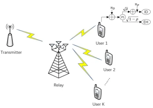
An AF relay cooperative network consisting of a source, a multi-antenna relay andK>1 destination nodes is considered. The source node and destination nodes are equipped with single antenna, whereas the relay is equipped withM>1 antennas. It is assumed that the source communicates with each destination via the multi-antenna relay node, and the direct links between the source and destinations nodes are sufficiently weak to be ignored. The received signal at the relay can be written as
y=hx+ns,r, (3.1)
whereh= [h1,h2, ...,hM]T ∈CM×1 andx denote channel response vector from the source
to the relay and transmitted signal, respectively; ns,r ∼CN(0,σs2,rI)is the additive white
Gaussian noise at the multi-antenna relay. The transmit power of the source isPs=E
|x2|
.
The received signal at the relay is amplified by a beamforming matrixW∈CM×M,W=
3.2 Network Model 47
given by
t=Wy. (3.2)
The power splitter is fitted at each receiver to dynamically split the received signals. The received signal at thekth receiver is splitted into two portions by a parameterρk∈[0,1], one
part is fed to ID and the remaining part is used for EH. Hence, the received signal split for ID at thekth receiver is given by
yk=√ρk gHkWhx+gHkWns,r+nk
+zk, (3.3)
wheregk = [g1k,g2k, ...,gMk]T ∈CM×1presents the channel coefficients from the relay to
thekth destination.nk∼CN(0,σk2)andzk∼CN(0,δk2)denote the antenna noise at thekth
destination node and the additional noise introduced by the ID at thekth destination node, respectively. The transmitted power by the relay can be expressed as
PT =∥t∥2=Ps∥hHW∥2+σs2,r∥W∥2. (3.4)
Then, the received SNR at thekth receiver can be written as
Γk=
ρkPs|gHk Wh|2
ρkσs2,r∥gHkW∥2+ρkσk2+δk2
, ∀k (3.5)
The harvested energy at thekth receiver can be expressed as
PE =ξk(1−ρk) |gHk Wh|
2+
σs2,r∥gHkW∥2+σk2, (3.6)
3.3 Problem Formulation and Solution 48
By jointly optimizing the transmit beamforming,{W}, and PS ratio,{ρk}, the relay transmit power minimization problem can be expressed as
min
W,ρk
Ps∥hHW∥2+σs2,r∥W∥2
s.t. Γk≥γk,PE ≥ek,0<ρk<1, ∀k. (3.7)
The achieved SNR for each destination should be higher than a threshold γk. Similarly,
EH constraint requires that the harvested energy at thekth receiver should be higher than a thresholdek. It is assumed that this problem is feasible throughout this chapter.
3.3
Problem Formulation and Solution
In this section, a robust optimization problem is proposed to jointly design beamforming and PS ratio based on the bounded CSI error model. Since the relay is used to help the communication between the source and the destinations, it is assumed that the channel between the source and the relay is perfectly known by the source. Meanwhile, it is also assumed that the relay only knows the imperfect CSI of the destinations. The channel uncertainty model is considered based on the assumption of the actual channel lying in an ellipsoid, which is centred at the channel mean. The actual channels can be modelled as
Gk={gk|gk=g˜k+∆gk,∆gHkCk∆gk≤1},∀k, (3.8)
where ˜gk denotes the estimation of the corresponding channel; ∆gk represent the channel
3.3 Problem Formulation and Solution 49
optimization problem in (3.7), the robust power minimization problem can be formulated as
min
W,ρk
Ps∥hHW∥2+σs2,r∥W∥2
s.t. Ps|(˜gk+∆gk)
HWh|2
σs2,r∥(˜gk+∆gk)HW∥2+σk2+δ
2
k
ρk
≥γk, ∀k,
|(˜gk+∆gk)HWh|2+σs2,r∥(g˜k+∆gk)HW∥2+σk2≥
ek
ξk(1−ρk)
∀k,
0<ρk<1, ∀k. (3.9)
The formulated robust problem is non-convex due to the quadratic function and error function [101]. In the following parts, this non-convex problem is solved by two approximation approaches.
3.3.1
Coefficient Uncertainty Model
In order to solve the non-convex problem (3.9), the quadratic terms need to be transformed to the easy-handled functions. The aim of the SNR constraint is to guarantee the minimum SNR greater than a threshold. It means that the numerator can be expressed by its underestimation value and the denominator can be expressed by its overestimation value. Based on the definition of vec(·) [106] and Cauchy-Schwarz inequality [107], the numerator and the denominator in the SNR constraint can be approximated as
|(g˜k+∆gk)HWh|2≥ |bHk f|2+ (εk−2
√
εk∥g˜k∥)∥h∥2∥f∥2,
∥(g˜k+∆gk)HW∥2≤ ∥Gkf∥2+M(εk+2
√
εk∥g˜k∥)∥f∥2, (3.10)
where bk =vec(˜gkhH), Gk = (g˜k⊗I), f =vec(W), and vec(·) denots vectorization of