704
A NOVEL TWO-DIMENSIONAL SPECTRAL/SPATIAL
HYBRID CODE FOR OPTICAL CODE DIVISION MULTIPLE
ACCESS SYSTEM
RIMA. MATEM1, S. A. ALJUNID2, M. N JUNITA3, C. B. M RASHIDI4, ISRAA. SHIHABAHMED5
Advanced Communication Engineering Centre of Excellence School of Computer and Communication Engineering (ACE CoE -SCCE),
Universiti Malaysia Perlis (UniMAP),Perlis, Malaysia,
E-mail: [email protected], [email protected], [email protected], [email protected], [email protected]
ABSTRACT
A newly two-dimensional hybrid code based on Zero Cross Correlation (ZCC) and Multi Diagonal (MD) codes (2D ZCC/MD) has been proposed for incoherent spectral/ spatial OCDMA system in this paper in order to supress MAI and mitigate PIIN. The 2D ZCC/MD keep the zero cross correlation property since the both of Zero Cross Correlation (ZCC) and Multi Diagonal (MD) codes have zero cross correlation property. Using the direct detection technique the proposed code is analysed where the performance of 2D ZCC/MD code is compared with existing 2D FCC/MDW and 2D DPDC. The analytical results prove that at low BER and high data 2D ZCC/MD can support more simultaneous user.
Keywords: Optical Code Division Multiple Access (OCDMA), Multiple Access Interference (MAI), Zero Cross-Correlation Code (ZCC), Multi-Diagonal code (MD), Phase Induced Intensity Noise.
1. INTRODUCTION
OCDMA (Optical Code Division Multiple Access) is a huge research area where it attracts many interesting research for decades. The importance of the system lies in the acquisition of certain characteristics that allow it to be interesting technique such as flexibility in high speed access network, high security, dynamic bandwidth assignment, large and effective bandwidth utilization [1]. OCDMA can be divided into five important schemes: frequency hopping [2], [3], time spreading [4], [5], spectral amplitude coding (SAC) [6], [7] and spatial coding [8], [9]. Due to the ability of suppression of Multiple Access Interference (MAI) completely by the spectral coding and mitigation Phase Induced Intensity Noise (PIIN), the spectral amplitude coding (SAC-OCDMA) has attracted a more interest recently [10], [11].
OCDMA can be classified into coherent and incoherent categories. A coherent OCDMA system is costly due to the high cost of the light source as a mode-locked laser while an incoherent OCDMA is cheaper and more suitable in optical network [12].
OCDMA can be implemented in one-dimensional (1D)[13], [14], two-dimensional (2D) [15], [16] or three-dimensional (3D) [17] for the main purpose to suppress Multiple Access Interference (MAI) and mitigation of Phase Induced Intensity Noise (PIIN) [18]. Many codes are introduced in two dimensional in order to overcome the obstacle of one dimensional as: 2-D diluted perfect difference (2-D DPD) spectral/spatial code provided by Yeh et al., based on the 1-D PD code and the dilution method [19], [20], 2-D spectral/spatial code based on modified quadratic congruence (MQC) code developed by Yin, et al.[21], 2-D spectral/spatial modified double weight code optical code division multi-access system (2D MDW) developed by Arief, A. R.and Aljunid, S. A [22], 2D wavelength/time hybrid Flexible Eross Correlation/Modified Double Weight (FCC/MDW) provided by Nui [23], [24].
705 construction. Section 3 presents system description. Section 4 presents the system performance where the numerical results and discussion are exhibited on the section 5. the last section gives the conclusion.
2. 2D HYBRID ZCC/MD CODE
CONSTRUCTION
Based on the combination of 1D MD code [7] and 1D ZCC code [25], the 2D-ZCC/MD code can be constructed. Let𝑋 𝑥 , 𝑥 , 𝑥 , … . , 𝑥 ,
𝑌 𝑦 , 𝑦 , 𝑦 , … . , 𝑦 With 𝑘 code weight of 1D-ZCC code and 𝑘 code weight of 1D-MD code. Denoted that 𝑤 is the code size of 1D-ZCC code and 𝑤 is the code size of 1D-MD code, so the code length of 𝑋, 𝑌 are 𝑀 𝑘 𝑤 , 𝑁 𝑘 𝑤
respectively. 𝑊 𝑤 𝑤 represents the code size of 2D-ZCC/MD.
2.1. 1D Zero Cross Correlation (ZCC) code
The Zero Cross Correlation (ZCC) code for SAC OCDMA was developed by Anuar et al (2009).[25] ZCC is designed with zero cross correlation property between its code words to improve the performance of SAC OCDMA system. ZCC is characterized by a matrix of 𝐾𝑥𝐿 where 𝐾
represents number of active users and 𝐿 represents the minimum code length. The number of active user 𝐾 and code length 𝐿 are given as:
𝐾 𝑤 1 (1)
𝐿 𝑤 𝑤 1 (2)
The construction of the code is designed from the modified double weight (MDW) code [26] where the matrix is generated as follow with the basic ZCC code (w=1):
𝑍𝐶𝐶 𝑤 1 0 11 0 (3)
According to the following map, the increase of the number of users is occurred:
𝑍𝐶𝐶 𝑤 2 𝑍0 𝑍0 (4)
𝑍𝐶𝐶 𝑤 3 𝑍0 𝑍0 (5)
The number of code weight can be increased by the general transformation below:
𝑍𝐶𝐶 𝐴 𝐵
𝐶 𝐷 (6)
Where:
𝐴: is 1, 𝑤 𝑤 1 matrix of zeros.
𝐵: represents 𝑤 replication of the matrix∑ 𝑗 0,1.
𝐶: contain of the duplication of the matrix from
𝑤 1.
𝐷: is the diagonal pattern of 𝑚 𝑛 with exchange column of zeros matrix 𝑚 𝑛.
An example for the transformation code from 𝑤 1 → 𝑤 2 → 𝑤 3 as follow:
𝑍𝐶𝐶 0 11 0 (7)
𝐴 𝐵
𝑍𝐶𝐶 0 0 00 1 0 1 0 1
1 0 1 0 1 0
0 0 0 (8)
𝐶 𝐷
𝐴 𝐵
𝑍𝐶𝐶
0 0 0 0 0 0 0 1 0 1 0 1 0 0 0 1 0 1 0 0 0 0 1 0 0 1 0 0 1 0 0 0 1 0 0 0 1 0 1 0 0 0 1 0 0 0 0 0
(9)
706
2.2. 1D Multi Diagonal (MD) code
One-dimensional Multi Diagonal (1D MD) was been developed by [7]. It is characterized by
𝑁(code length), 𝑤(code weight) and 𝜆 (in phase cross correlation)
For the code sequence 𝑋 𝑥 , 𝑥 , … . , 𝑥 , 𝑌 𝑦 , 𝑦 , … . , 𝑦 . The cross correlation expression can be expressed by 𝜆 ∑ 𝑥 𝑦
1𝐷 𝑀𝐷 (Multi Diagonal) possesses zero cross correlation 𝜆 0.
The matrix of 1D MD code consists of 𝐾𝑥𝑁 where
𝐾 is the number of user, 𝑁is the code length. The choice of the weight value is free and 𝑁 𝐾𝑤. The 1D MD code can be designed as below:
Step1:
A sequence of diagonal matrix can be constructed using the value of the weight 𝑤 and number of user 𝐾 , according to these value the 𝑖 𝑖 1,2,3, … . 𝐾 is the index of rows in each matrix and
𝑗 𝑗 1,2,3, … . . , 𝑤 where j is the number of diagonal matrix.
Step2:
The MD sequences can be computed for each diagonal matrix using the equation below:
𝑆, 𝑖 𝑓𝑜𝑟 𝑗𝑖 1 𝑖 , 𝑗 𝑒𝑣𝑒𝑛𝑜𝑑𝑑 (10)
𝑆, ⎣ ⎢ ⎢ ⎢ ⎢ ⎢ ⎡12 3 . . . 𝐾⎦ ⎥ ⎥ ⎥ ⎥ ⎥ ⎤ , 𝑆, ⎣ ⎢ ⎢ ⎢ ⎢ ⎢ ⎡𝐾. . . 3 2 1⎦ ⎥ ⎥ ⎥ ⎥ ⎥ ⎤ , 𝑆, ⎣ ⎢ ⎢ ⎢ ⎢ ⎢ ⎡12 3 . . . 𝐾⎦ ⎥ ⎥ ⎥ ⎥ ⎥ ⎤ ,… (11)
Each element of the 𝑆, matrices represents the position of one in 𝑇, matrices with 𝐾𝑥𝐾dimensions. Where 𝑇, 𝑆, , 𝑇, 𝑆, ,…., 𝑇, 𝑆, (12)
𝑇, 1 0 ⋮ 0 0 1 ⋮ ⋯ … … ⋱ … 0 0 ⋮ 1 , 𝑇, 0 0 ⋯ 1 ⋯ ⋯ … … 0 1 ⋱ ⋯ 1 0 ⋮ 0 ,…., 𝑇, 1 0 ⋮ 0 0 1 ⋮ ⋯ … … ⋱ … 0 0 ⋮ 1 (13) Step3: The construction of the matrix of MD code of power 𝐾𝑥𝑁 is based on the combination of diagonals matrices. In a matrix each row is a single code sequence. 𝑀𝐷 𝑇, ⋮ 𝑇, ⋮ ⋯ ⋯ ⋮ 𝑇, (14)
𝑀𝐷 ⎣ ⎢ ⎢ ⎢ ⎡𝑎𝑎 ,, 𝑎 𝑎,, ⋯ 𝑎 ⋯ 𝑎,, 𝑎 , 𝑎 , ⋯ 𝑎 , ⋮ ⋮ ⋯ ⋮ 𝑎 , 𝑎 , ⋯ 𝑎 , ⎦ ⎥ ⎥ ⎥ ⎤ (15)
The following table give an example of MD code with 𝐾 4, 𝑤 3 Tablei: The MD Code With 𝐾 4, 𝑤 3 𝑖 Code sequence 1 2 3 4 1 0 0 0 0 0 0 1 1 0 0 0 0 1 0 0 0 0 1 0 0 1 0 0 0 0 1 0 0 1 0 0 0 0 1 0 0 0 0 1 1 0 0 0 0 0 0 1 The cross correlation of newly code can be obtained using four characteristics are given as follow: 𝐴 𝑌 𝑋 (16)
𝐴 𝑌 𝑋 (17)
𝐴 𝑌 𝑋 (18)
𝐴 𝑌 𝑋 (19)
707 and 𝑌 respectively. The cross correlation of hybrid 2D ZCC/MD code 𝐴 and 𝐴 , is formulated as:
𝑅 𝑔, ℎ ∑ ∑ 𝑎 𝑎 (20)
Where 𝑎 depicts the 𝑖, 𝑗 of 𝐴 and
𝑎 is the 𝑖, 𝑗 of 𝐴 , . TableII shows the
cross correlation between any two codes 𝐴 and
𝐴 , of 2D Hybrid ZCC/MD code produced from
the equation (20).
Tableii: Cross Correlation Of 2D ZCC/MD Hybrid Code
The cross correlation of 𝐴, and 𝐴 , can be
calculated as follows:
𝑅 𝑔, ℎ 𝑎, 𝑎, 𝑔, ℎ
𝑘 𝑘 𝑓𝑜𝑟 𝑔 0, ℎ 0
0 𝑜𝑡ℎ𝑒𝑟𝑤𝑖𝑠𝑒 (21)
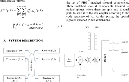
3. SYSTEM DESCRIPTION
Figure1: Block Diagram Of A 2D Hybrid ZCC/MD Spectral/Spatial OCDMA System
Based on the direct detection technique, 2D ZCC/MD is designed as illustrated in Figure1. It consists of 𝑤 𝑤 pairs of transmitters and receivers, the star coupler to connect the transmitter and the receiver. Using the assigned codeword, the incoming data will be encoded and transmitted to the receiver via star coupler. At the receiver, the encoded data will be decoded through up one combiner and all codewords from different users are correlated.figure2shows the construction of 2D ZCC/MD transmitter, it consists of incoherent light source (BLS), to send the data, an electrical to optical modulator (EOM) to modulate the signal coming from BLS, one splitter for the spectral encoding, two (2) Fiber Bragg Grating (FBG) with the same number of grating but opposite arrangement for the spatial encoding. The incoming data from BLS will be converted to the optical signal through EOM with ON-OFF Keying format; this modulated data will pass through the FBG1 for the spectral encoding purpose according to
[image:4.612.92.522.380.655.2]𝑋 the spectral code sequence. The spectral components of optical pulse either matched to 1s of a code are filtered back and the other are filtered out. FBG2 is designed to compensate the delay of the set of FBG1 matched spectral components. These matched spectral components transmit to optical splitter where these are split into 𝑘 equal parts to send it to the star coupler according to the code sequence of 𝑌. At this phase, the optical signal is encoded in two dimensions.
Figure 2: The Construction Of Transmitter
Figure3 depicts the construction of the receiver where it is designed in order to suppress MAI and used as information bit recovery. It consists of one
𝑅 𝑅 𝑅 𝑅
𝑔 0, ℎ 0 𝑘 𝑘 0 0 0 𝑔 0, ℎ 0 0 𝑘 𝑘 0 0 𝑔 0, ℎ 0 0 0 𝑘 𝑘 0 𝑔 0, ℎ 0 0 0 0 𝑘 𝑘
Transmitter (0,0)
Star cou
pler
Receiver (0,0)
Transmitter (M-1,N-1)
Receiver (0,0)
Receiver (M-1,N-1)
Transmitter (0,1) light
source
EOM
Information bit
FBG1 FBG2
Sp
litter
To coupler1
To coupler2
708 combiner, one direct detection technique part and one integrator. The direct detection technique part in turn consists of two sets of Fiber Bragg Grating (FBG1 and FBG2), two circulators and one Photo detector (PD). The incoming spatial code sequence
𝑌 from the star coupler are received and combined by the combiner. The spectral components which are matched to “1s” of the spectral code sequence
𝑋 are reflected back by FBG1. FBG2 with the same grating but opposite arrangement used to compensate the run-trip delay. The photo detectors (PD) convert the optical signals to electronic signals and then pass them to the integrator.
Figure3: The construction of the receiver.
4. SYSTEM PERFORMANCE
According to the zero cross correlation property of the code 2D ZCC/MD, there is no overlapping in a spectra of different users, thus the effect of MAI have been removed. The effects of thermal noise, PIIN, and shot noise in the photo-detector have been considered in the analysis. The Gaussian approximation is employed to calculate the BER. The total noise photocurrent variance can be expressed as follow:
〈𝑖 〉 〈𝑖 〉 〈𝑖 〉 〈𝑖 〉
𝐵𝐼 𝜏 2𝑒𝐵𝐼 (21)
Where 𝑒 is the electron charge, 𝐼 is the average photocurrent. 𝐵 is the electrical bandwidth, 𝑇 is the absolute temperature, 𝐾 is Boltzmann's constant, 𝑅 is the load resistance and 𝜏 is the coherence time of the light which expressed as:
𝜏 (22)
Where 𝑆 𝑣 consists the single sideband power spectral density. To simplify the analysis, four assumptions are made [9]:
We defined 𝑈 𝑣, 𝑖 as follows:
𝑈 𝑣, 𝑖 𝑢 𝑣 𝑣 ∆ 𝑀 2𝑖
𝑢 𝑣 ∆ 𝑀 2𝑖 2 (23)
Comb
iner
From coupler1
From coupler2
From couplerN
FBG2 FBG1
709 Where 𝑈 𝑣, 𝑖 is a unit step function defined as:
𝑢 𝑣 1 𝑣0 𝑣 00 (24)
The power spectral density (PSD) of the received signals can be written as
𝑟 𝑣 ∆ ∑ 𝑑 𝑘 ∑ ∑ 𝑎 , 𝑘 𝑈 𝑣, 𝑖
(25)
Where 𝑘 and 𝑘 are the code weights of spectral and spatial respectively, 𝑃 is the effective source power at the receiver, 𝑁 and 𝑀 are the code lengths of spatial and spectral code sequences respectively , 𝑊 is the number of active users, 𝑑 𝑘
is the data bit of 𝑊 user which can be “1” or “0” and 𝑎 , is an element of the 𝑘 user's codeword.
depending on the cross correlation between 𝐴 , and
𝐴 , obtain the output currents of PD at receiver
(0,0) is obtained as follows:
𝐼 𝑅 𝐺 𝑣 𝑑𝑣
∆ ∑ 𝑑 𝑤 𝑅 𝑖, 𝑗 𝑈 𝑣, 𝑖 𝑑𝑣 ∆
∆ 𝑘 𝑘 ∑ 𝑑 𝑤 𝑅 𝑖, 𝑗
(26)
Where 𝜂 is the quantum efficiency of the photo-diode, 𝑅 is the responsivity of the photo-diode given by 𝑅 𝜂𝑒/ℎ𝑣 and ℎ is Plank's constant. Since, 𝑀 𝑤 𝑘 and 𝑊 𝑤 𝑤 , then:
𝐼 (27)
Phase Induced Intensity Noise (PIIN) can be calculated as:
〈𝑖 〉 𝐵𝐼 𝐺 𝑣 𝑑𝑣 𝐺 𝑣 𝑑𝑣
𝐵𝑅 𝐺 𝑣 𝑑𝑣
𝐵𝑅 ∆ ∑ 𝑑 𝑘 𝑅 𝑈 𝑖, 𝑗 𝑑𝑣
𝐴 , X 1 0 1 0 0 0 1 0 0 0 0 0 X 0 1 0 0 1 0 0 0 1 0 0 0 X 0 0 0 0 0 0 0 1 0 1 0 1 𝑋
Y ⎣ ⎢ ⎢ ⎢ ⎢ ⎡10
0 0 0 1⎦⎥ ⎥ ⎥ ⎥ ⎤ ⎣ ⎢ ⎢ ⎢ ⎢
⎡1 0 1 0 0 0 1 0 0 0 0 00 0 0 0 0 0 0 0 0 0 0 0 0 0 0 0 0 0 0 0 0 0 0 0 0 0 0 0 0 0 0 0 0 0 0 0 0 0 0 0 0 0 0 0 0 0 0 0 1 0 1 0 0 0 1 0 0 0 0 0 ⎦⎥
⎥ ⎥ ⎥ ⎤ ⎣ ⎢ ⎢ ⎢ ⎢
⎡0 1 0 0 1 0 0 0 1 0 0 00 0 0 0 0 0 0 0 0 0 0 0 0 0 0 0 0 0 0 0 0 0 0 0 0 0 0 0 0 0 0 0 0 0 0 0 0 0 0 0 0 0 0 0 0 0 0 0 0 1 0 0 1 0 0 0 1 0 0 0⎦⎥
⎥ ⎥ ⎥ ⎤ ⎣ ⎢ ⎢ ⎢ ⎢
⎡0 0 0 0 0 0 0 1 0 1 0 10 0 0 0 0 0 0 0 0 0 0 0 0 0 0 0 0 0 0 0 0 0 0 0 0 0 0 0 0 0 0 0 0 0 0 0 0 0 0 0 0 0 0 0 0 0 0 0 0 0 0 0 0 0 0 1 0 1 0 1⎦⎥
⎥ ⎥ ⎥ ⎤ Y ⎣ ⎢ ⎢ ⎢ ⎢ ⎡01
0 0 1 0⎦⎥ ⎥ ⎥ ⎥ ⎤ ⎣ ⎢ ⎢ ⎢ ⎢
⎡0 0 0 0 0 0 0 0 0 0 0 01 0 1 0 0 0 1 0 0 0 0 0 0 0 0 0 0 0 0 0 0 0 0 0 0 0 0 0 0 0 0 0 0 0 0 0 1 0 1 0 0 0 1 0 0 0 0 0 0 0 0 0 0 0 0 0 0 0 0 0⎦⎥
⎥ ⎥ ⎥ ⎤ ⎣ ⎢ ⎢ ⎢ ⎢
⎡0 0 0 0 0 0 0 0 0 0 0 00 1 0 0 1 0 0 0 1 0 0 0 0 0 0 0 0 0 0 0 0 0 0 0 0 0 0 0 0 0 0 0 0 0 0 0 0 1 0 0 1 0 0 0 1 0 0 0 0 0 0 0 0 0 0 0 0 0 0 0⎦⎥
⎥ ⎥ ⎥ ⎤ ⎣ ⎢ ⎢ ⎢ ⎢
⎡0 0 0 0 0 0 0 0 0 0 0 00 0 0 0 0 0 0 1 0 1 0 1 0 0 0 0 0 0 0 0 0 0 0 0 0 0 0 0 0 0 0 0 0 0 0 0 0 0 0 0 0 0 0 1 0 1 0 1 0 0 0 0 0 0 0 0 0 0 0 0⎦⎥
⎥ ⎥ ⎥ ⎤ Y ⎣ ⎢ ⎢ ⎢ ⎢ ⎡00
1 1 0 0⎦ ⎥ ⎥ ⎥ ⎥ ⎤ ⎣ ⎢ ⎢ ⎢ ⎢
⎡0 0 0 0 0 0 0 0 0 0 0 00 0 0 0 0 0 0 0 0 0 0 0 1 0 1 0 0 0 1 0 0 0 0 0 1 0 1 0 0 0 1 0 0 0 0 0 0 0 0 0 0 0 0 0 0 0 0 0 0 0 0 0 0 0 0 0 0 0 0 0⎦
⎥ ⎥ ⎥ ⎥ ⎤ ⎣ ⎢ ⎢ ⎢ ⎢
⎡0 0 0 0 0 0 0 0 0 0 0 00 0 0 0 0 0 0 0 0 0 0 0 0 1 0 0 1 0 0 0 1 0 0 0 0 1 0 0 1 0 0 0 1 0 0 0 0 0 0 0 0 0 0 0 0 0 0 0 0 0 0 0 0 0 0 0 0 0 0 0⎦
⎥ ⎥ ⎥ ⎥ ⎤ ⎣ ⎢ ⎢ ⎢ ⎢
⎡0 0 0 0 0 0 0 0 0 0 0 00 0 0 0 0 0 0 0 0 0 0 0 0 0 0 0 0 0 0 1 0 1 0 1 0 0 0 0 0 0 0 1 0 1 0 1 0 0 0 0 0 0 0 0 0 0 0 0 0 0 0 0 0 0 0 0 0 0 0 0⎦
⎥ ⎥ ⎥ ⎥ ⎤ 𝑌
710
𝐵𝑃 𝑅
𝑘 ∆𝑣 𝑀 𝑘 𝑘 𝑑 𝑘 𝑅 𝑖, 𝑗
0
𝐵 ∆ (28)
Consequently, the total noise where the probability of each user sending bit 1 is equal so:
〈
𝑖𝑛𝑜𝑖𝑠𝑒2〉
〈
𝑖𝑃𝐼𝐼𝑁2〉 〈
𝑖𝑠ℎ𝑜𝑡2〉 〈
𝑖𝑡ℎ𝑒𝑟𝑚𝑎𝑙2〉
(29)
〈
𝑖𝑛𝑜𝑖𝑠𝑒2〉
𝐵𝐼2𝜏 2𝑒𝐵𝐼4𝐾𝑏𝑇𝑛𝐵
𝑅𝐿 (30)
From the previous equations 𝐼𝑛𝑜𝑖𝑠𝑒 can written as
〈
𝑖𝑛𝑜𝑖𝑠𝑒2〉
〈
𝑖𝑃𝐼𝐼𝑁2〉 〈
𝑖𝑠ℎ𝑜𝑡2〉 〈
𝑖𝑡ℎ𝑒𝑟𝑚𝑎𝑙2〉
〈
𝑖𝑃𝐼𝐼𝑁2〉
𝐵𝑅2𝑃𝑠𝑟2𝑤2𝑘1
∆𝑣𝑊 (31)
〈
𝑖𝑠ℎ𝑜𝑡2〉
2𝑒𝐵𝑅𝑃𝑠𝑟𝑤2
𝑊 (32)
〈
𝑖𝑡ℎ𝑒𝑟𝑚𝑎𝑙2〉
4𝐾𝑏𝑇𝑛𝐵
𝑅𝐿 (33)
〈
𝑖𝑛𝑜𝑖𝑠𝑒2〉
𝐵𝑅2𝑃𝑠𝑟2𝑘12
∆𝑣𝑊 2𝑒𝐵
𝑅𝑃𝑠𝑟𝑤2 𝑊
4𝐾𝑏𝑇𝑛𝐵
𝑅𝐿 (34)
Note that the probability of sending bit “1” at any time for each user is 1/2:
〈
𝑖𝑛𝑜𝑖𝑠𝑒2〉
𝐵𝑅2𝑃𝑠𝑟2𝑘12 2∆𝑣𝑊
𝑒𝐵𝑅𝑃𝑠𝑟𝑤2 𝑊
4𝐾𝑏𝑇𝑛𝐵
𝑅𝐿 (35)
Finally, the average signal to noise ratio (SNR) can be calculated as
𝑆𝑁𝑅 〈 〉
∆
(36)
from SNR, The BER can be expressed as follows:
𝐵𝐸𝑅
(37)
Where
𝑒𝑟𝑓𝑐
√ exp 𝑦 𝑑𝑦 (38)
Table IV : Link parameters
PD quantum efficiency
𝑅 0.75
Spectral width of broadband light source
∆𝜆 30𝑛𝑚 ∆𝜆 3.75
Operating
wavelength 𝜆0 1.55𝜇𝑚
Electrical bandwidth
𝐵 320𝑀𝐻𝑧
Data
transmission rate 𝑅𝑏 622𝑀𝑏𝑝𝑠 Receiver noise
temperature 𝑇𝑛 300𝐾
Receiver load
resistor 𝑅𝐿 1030Ω
Boltzmann’s
constant 𝐾𝑏 1.38 10
23 𝑊
/𝐾/𝐻𝑧
Electron charge 𝑒
1.60217646 10 𝑐𝑜𝑢𝑙𝑜𝑚𝑏𝑠
Light velocity 𝐶 3 10 𝑚/𝑠
5. RESULTS AND DISCUSSION
TableV exhibits the parameters used to analyze the performance of the 2D ZCC/MD code and obtain the numerical results.
Figure4: BER Against Number Of Users Where Data Rate Is Rb=1Gbps And Effective Power Is Psr=-10dbm
Figure4 shows the variation of BER versus the number of users of the codes 2D ZCC/MD (M=63, N=3) compared to 2D DPDC (M=91, N=3), 2D FCC/MDW (M=23, N=7), 2D ZCC/MD (M=23,
0 50 100 150 200 250 300 350 400
10-15
10-10 10-5 100
Number of users
BER
711 N=7), 1D RD (N=92) and 1D MDW (N=58) where effective power Psr equal to -10dBm and data rate Rb=1Gbps. It can be seen that 2D ZCC/MD exhibit the better performance than other codes. At BER equal to 10 9 the 2D ZCC/MD (M=23, N=7) can
support until 210 user.
Figure5: BER Versus Number Of Users With Data Rate Is Rb=2.5Gbps And Effective Power Is Psr=-10dbm
Figure5 illustrates also the variation of the BER versus number of user of the same codes but with Psr=-10dBm and data rate Rb=2.5Gbps. This figure confirms the observations given by the previous figure. It can be clearly seen that number of user is increased where for the 2D ZCC/MD (M=23, N=7) code can reach 315 user at BER equal to 10 9.
Figure6: BER Versus Effective Power Psr When K=100 User And Data Rate Is Rb=622Mbps
Figure6 shows the relation between the BER and the effective power in dBm when the number of user is equal to 100 and data rate equal to 622Mbps. The figure apparent that 2D ZCC/MD (M=23, N=7) is the best at high power and it has a minimum BER -24 comparing to the other codes. 2D ZCC/MD
indicates that the superior performance is coming from the ability of the code to fully to suppress the effect of the MAI and mitigate PIIN.
Figure7: BER Versus Date Rate When The Effective Power Is Psr=-10dbm And The Number Of User Is
K=100 User.
Figure7 shows the variation of BER versus the data transmission rate of each user with similar code length when the number of user is 100 and the effective source power 10 𝑑𝐵𝑚. At the BER equal to 10 9 , the figure demonstrates that 2D ZCC/MD can accommodate the higher data transmission rate for each user with a similar code length is used compared to the other codes.
6. CONCLUSION
The OCDMA is an interesting scheme due to characteristic such as: flexible bandwidth, asynchronous access, flexibility of implementation differential QOS and ability to support multimedia services. A newly two dimensional code has been proposed referred as 2D hybrid code for spectral/spatial OCDMA system. The construction of this code is based on the combination of 1D ZCC code and 1D MD code. The performance of this new code has been evaluated by using the analytical analysis. The proposed code has the MAI suppression property where the proposed system has a low BER. The proposed code represents the better performance compared to other codes so the system could robustly accommodate more users.
ACKNOWLEDGEMENT
The author would like to acknowledge the support from Fundamental Research Grant Scheme (FRGS) under Prof .Dr. Syed Alwee Aljunid, Department of Higher Education, Ministry of Higher Education Malaysia for the assistance with The grant.
0 50 100 150 200 250 300 350 400
10-15
10-10 10-5 100
Number of users
BER
2D ZCC/MD(M=63,N=3) 2D FCC/MDW (M=23,N=7) 2D ZCC/MD(M=23,N=7) 2D DPDC (M=91,N=3) 1D RD (N=92) 1D MDW (N=58)
-30 -25 -20 -15 -10 -5 0 5 10
10-25 10-20 10-15 10-10 10-5 100
effective received power
BER
2-D ZCC/MD (M=63, N=3) (data rate=622 Mbps) 2-D FCC/MDW (M=23, N=7)(data rate=622Mbps) 2-D DPDC (M=63, N=3)(data rate=622Mbps) 1D RD (N=50)(data rate=622Mbps) 1D MDW (N=58)(data rate=622Mbps)
0 1 2 3 4 5 6 7 8 9 10
x 109
10-25 10-20
10-15 10-10 10-5 100
data bit rate
BER
712
REFERENCES
[1] Abdullah, Amir Razif Arief Jamil, Syed Alwee Aljunid, Anuar Mat Safar, Junita Mohd Nordin, and R. Badlishah Ahmad. "Mitigation of multiple access interference using two-dimensional modified double weight codes for optical code division multiple access systems." Optical Engineering 51, no. 6 (2012): 065007-1..
[2] Fathallah, Habib, Leslie A. Rusch, and Sophie LaRochelle. "Passive optical fast frequency-hop CDMA communications system." Journal of Lightwave Technology 17, no. 3 (1999): 397.
[3] Inaty, Elie, Hossam MH Shalaby, and Paul Fortier. "On the cutoff rates of a multiclass OFFH-CDMA system." IEEE transactions on communications 53, no. 2 (2005): 323-334. [4] Chung, Fan RK, Jawad A. Salehi, and Victor K.
Wei. "Optical orthogonal codes: design, analysis and applications." IEEE Transactions on Information theory 35, no. 3 (1989): 595-604.
[5] Weng, Chi-Shun, and Jingshown Wu. "Perfect difference codes for synchronous fiber-optic CDMA communication systems." Journal of Lightwave Technology 19, no. 2 (2001): 186. [6] Smith, Elwyn DJ, Richard J. Blaikie, and
Desmond P. Taylor. "Performance enhancement of spectral-amplitude-coding optical CDMA using pulse-position modulation." IEEE Transactions on Communications 46, no. 9 (1998): 1176-1185. [7] Abd, Thanaa Hussein, S. A. Aljunid, Hilal
Adnan Fadhil, and N. M. Saad. "Design and simulation a new code with zero cross correlation for SAC-OCDMA networks." Australian J Basic and Appl Sci 6, no. 3 (2012): 112-119.
[8] Kitayama, Ken-ichi. "Novel spatial spread spectrum based fiber optic CDMA networks for image transmission." IEEE Journal on Selected Areas in Communications 12, no. 4 (1994): 762-772. Selected Areas in
Communications, 12(4), 762-772. (1994).
[9] Yeh, Bih-Chyun, Cheing-Hong Lin, and Jingshown Wu. "Noncoherent spectral/spatial OCDMA system using two-dimensional hybrid codes." Journal of Optical Communications and Networking 2, no. 9 (2010): 653-661.
[10] Rashidi, C. B. M., Mat Safar Anuar, and S. A. Aljunid. "Study of direct detection technique for zero cross correlation code in OCDMA."
In Computer and Communication Engineering (ICCCE), 2010 International Conference on, pp. 1-5. IEEE, 2010.
[11] Rashidi, C. B. M., S. A. Aljunid, F. Ghani, Hilal A. Fadhil, and M. S. Anuar. "Cardinality Enhancement Using Flexible Cross Correlation (FCC) Code for Spectral Amplitude Coding Optical Code Division Multiple Access Systems." Journal of Applied Sciences Research 8, no. 12 (2012): 5614-5626.
[12] Huang, Jen-Fa, and Yao-Tang Chang. "Incoherent hybrid spectral polarization and amplitude coding implemented with specified orthogonal ternary code over balanced photo-detectors." In Communication Networks and Services Research Conference, 2006. CNSR 2006. Proceedings of the 4th Annual, pp. 8-pp. IEEE, 2006.
[13] Wei, Zou, H. M. H. Shalaby, and H. Ghafouri-Shiraz. "Modified quadratic congruence codes for fiber Bragg-grating-based spectral-amplitude-coding optical CDMA systems."Journal of Lightwave Technology 19, no. 9 (2001): 1274-1281.
[14] M.N.Junita. Development of New Code for Subcarrier Multiplexed-Optical Code Division Multiple Access System. 2013 (Thesis)
[15] Wan, Shengpeng, Xingdao He, and Jizhou Sun. "A novel 2D-OCDMA system with dynamic optimum decision threshold by estimating the number of active users." Optics Communications 282, no. 24 (2009): 4776-4778.
[16] Yang, Chao-Chin, Jen-Fa Huang, and I-Min Chiu. "Performance analyses on hybrid MQC/M-sequence coding over frequency/spatial optical CDMA system." IEEE Transactions on communications 55, no. 1 (2007): 40-43.
[17] Kadhim, Rasim Azeez, Hilal Adnan Fadhil, S. A. Aljunid, and Mohamad Shahrazel Razalli. "PERFORMANCE ENHANCEMENT OF A THREE DIMENSIONAL OCDMA SYSTEMS BASED ON A NEW CODE." Journal of Theoretical and Applied Information Technology 81, no. 3 (2015): 589.
[18] Rasim Azeez Kadhim n , Hilal Adnan Fadhil, S.A. Aljunid, Mohamad Shahrazel Razalli. A new two dimensional spectral/spatial multi-diagonal code for noncoherent optical code division multiple access (OCDMA) systems.
713 www.elsevier.com/locate/optcom. Optics Communications 329 (2014) 28–33
[19] Yeh, Bih-Chyun, Cheing-Hong Lin, Chun-Liang Yang, and Jingshown Wu. "Noncoherent spectral/spatial optical CDMA system using 2-D diluted perfect difference codes." Journal of Lightwave Technology 27, no. 13 (2009): 2420-2432.
[20] Yeh, Bih-Chyun, Cheing-Hong Lin, Chun-Liang Yang, and Jingshown Wu. "Noncoherent spectral/spatial optical CDMA system using 2-D diluted perfect difference codes." Journal of Lightwave Technology 27, no. 13 (2009): 2420-2432.
[21] Yin, Hongxi, Le Ma, Hongbin Li, and Lixin Zhu. "A new family of 2D wavelength/time codes with large cardinality for incoherent spectral amplitude coding OCDMA networks and analysis of its performance." Photonic Network Communications 19, no. 2 (2010): 204-211.
[22] Arief, Amir Razif, Syed Alwee Aljunid, M. S. Anuar, M. N. Junita, and R. B. Ahmad. "Cardinality enhancement of spectral/spatial modified double weight code optical code division multi-access system by PIIN suppression." Optik-International Journal for Light and Electron Optics 124, no. 19 (2013): 3786-3793.
[23] Keraf, N. Din, S. A. Aljunid, A. R. Arief, M. S. Anuar, C. B. M. Rashidi, P. Ehkan, and M. N. Nurol. "An optimal cardinality of Wavelength/Time incoherent OCDMA system using 2-D Hybrid FCC-MDW Code." In Electronic Design (ICED), 2014 2nd International Conference on, pp. 356-361. IEEE, 2014.
[24] N. Din Keraf, S. A. Aljunid, A. R. Arief, M. N. Nurol, M. S. Anuar, C. B. M. Rashidi, P. Ehkan Noise Mitigation for OCDMA System with Wavelength/Time 2D Hybrid Code. Proc. of 2014 IEEE 5th International
Conference on Photonics (ICP), Kuala
Lumpur, 2-4 Sept. 2014.
[25] Anuar, M. S., Aljunid, S. A., Saad, N. M., & Hamzah, S. M. New design of spectral amplitude coding in OCDMA with zero cross-correlation.Optics Communications, 282(14), (2009). 2659-2664.
[26] Aljunid, S. A., M. D. A. Samad, M. Othman, M. H. Hisham, A. H. Kasiman, and M. K. Abdullah. "Development of modified double-weight code and its implementation in multi-rate transmissions." In Networks, 2005. Jointly held with the 2005 IEEE 7th Malaysia