
Demonstration of sub-luminal propagation of
single-cycle terahertz pulses for particle
acceleration
D.A. Walsh
1,2, D.S. Lake
2,3, E.W. Snedden
1,2, M.J. Cliffe
2,3, D.M. Graham
2,3& S.P. Jamison
1,2The sub-luminal phase velocity of electromagnetic waves in free space is generally unob-tainable, being closely linked to forbidden faster than light group velocities. The requirement of sub-luminal phase-velocity in laser-driven particle acceleration schemes imposes a limit on the total acceleration achievable in free space, and necessitates the use of dispersive structures or waveguides for extending the field-particle interaction. We demonstrate a travelling source approach that overcomes the sub-luminal propagation limits. The approach exploits ultrafast optical sources with slow group velocity propagation, and a group-to-phase front conversion through nonlinear optical interaction. The concept is demonstrated with two terahertz generation processes, nonlinear optical rectification and current-surge rectification. We report measurements of longitudinally polarised single-cycle electric fields with phase and group velocity between 0.77cand 1.75c. The ability to scale to multi-megawatt-per-metre
field strengths is demonstrated. Our approach paves the way towards the realisation of cheap and compact particle accelerators with femtosecond scale control of particles.
DOI: 10.1038/s41467-017-00490-y OPEN
1Accelerator Science and Technology Centre, Science and Technology Facilities Council, Daresbury Laboratory, Keckwick Lane, Daresbury,
F
emtosecond duration relativistic electron beams are in demand for ultrafast electron diffraction, as sources of femtosecond X-rays in free-electron laser facilities such as the Linac Coherent Light Source (LCLS)1and SPring-8 Angstrom Compact Free Electron Laser (SACLA)2, and for future lepton colliders such as CERN’s proposed 35 km long Compact Linear Collider, CLIC3. For over 50 years gigahertz frequency electro-magneticfields have been the drivers in increasingly sophisticated generations of particle accelerators, but face significant challenges in meeting the demands for control and manipulation of particle beams on the femtosecond scale. Physical limits in the achievable accelerationfield strengths at gigahertz frequencies also underlies the km-scale and multi-megawatt power consumption of high-energy accelerators.To overcome the limitations of few-gigahertz frequency acceleration structures many concepts for millimetre-wave and terahertz frequency acceleration have been investigated. Among those that have demonstrated significant potential are beam-driven dielectric lined structures4,5, W-band resonant structures operating at 91 GHz6, and high frequency photonic band gap structures7. The surface breakdownfield strengths at these higher frequencies significantly exceed those of few-GHz radio frequency structures8, and have even been observed to exceed 10 GeV m−1 in beam-driven dielectric structures9. Laser-based approaches have also demonstrated strong potential for high gradient and compact particle acceleration, with laser-plasma wakfield accel-eration (LPWFA) producing quasi-monochromatic electron beams through self-injection of electrons from the background plasma10–13. Through systematic investigation and improvements over the last decade, LPWFA now has a demonstrated capability of multi-GeV electron acceleration, acceleration gradients exceeding 10 GeV m−114, 15, and generation of femtosecond duration electron bunches16–19. However, despite the very high gradients and acceleration achieved, exploitation of LPWFA is hampered by shot-to-shot stability in the electron beam para-meters and by a relatively large energy spread of the accelerated beams. Laser-driven photonic and dielectric structures also have the potential for GeV m−1acceleration gradients20,21, although the small sub-micron structure apertures and few-fs electro-magnetic periods present significant challenges in injection, and in controlling wakefields and beam space-charge effects.
Recently there has been significant interest in the use of laser generated terahertz pulses for particle acceleration as a potential new approach with promise to overcome both the limitations of radio frequency (RF) acceleration, and the significant challenges remaining in the other high-frequency concepts. With their picosecond period fields, terahertz sources offer the ability to capture and finely control few-fs particle beams22–24, while the few-ps envelope of energy content offers orders of magnitude improvement in matching energy localisation to the charged particles being accelerated. A terahertz acceleration scheme has recently demonstrated the ability to accelerate non-relativistic particles, using a waveguide structure to accelerate electrons from an initial energy of 60–67 keV over a distance of 3 mm25. Ultrafast terahertz pulse sources have also recently been shown to produce GV m−1 electric field strengths26–28, exceeding by an order of magnitude that of normal-conducting RF accelerators29, and two orders of magnitude that of superconducting accelerators such as the European XFEL30. To obtain continuous and length-scalable acceleration of relativistic particles however, requires phase-matching of the electromagnetic carrier wave with the
β=v/c<1 velocity of the particles in order that these high electricfield strengths can be exploited.
The highest field strength terahertz sources are obtained in near-single-cycle electromagnetic pulses, containing an excep-tionally broadband coherent spectrum. The single-cycle nature of
the pulse is both central to its application for particle acceleration, and to-date the principal obstacle to scalable implementation. The single-cycle near transform limited time profile gives rise to the highestfield strengths, and the 100 fs to 1 ps carrier period is ideally matched to capture and control particle beams with sub 10 fs duration; additionally the broadband coherence allows for customised electricfield temporal profiles, such as linear ramps. With an electromagnetic energy temporally concentrated within 1 ps and well matched to the duration of particle bunches, orders of magnitude efficiency gains over conventional RF acceleration (with the μs and msfills times of normal and superconducting cavities, respectively) may be achieved.
To obtain acceleration over extended interaction lengths requires generation of electromagnetic modes with longitudinal electricfield polarisation, and real or effective phase-matching of the electromagnetic carrier wave with the β<1 velocity of the relativistic particles. Longitudinal polarised terahertz radiation can be obtained through coherent spatial addition of phase or polarity offset beams31, through selective coupling into (or onto) geometrically defined structures32, 33, using air-plasma genera-tion34, using a segmented nonlinear generation crystal35, or using radially biased photoconductive antennas36–40. The phase-matching problem is however more fundamental; free space beams such as TEM10 Gaussian modes necessarily have phase
velocities greater than the vacuum speed of light,c, with the Guoy
π-phase shift ultimately limiting available interaction lengths to less than a Rayleigh length41. Waveguiding is capable of obtaining
β<1 phase-matching at a single frequency (or subset of fre-quencies) but such structures are necessarily subject to dispersion relations that preclude maintaining the single-cycle field profile over an extended region. For few-cycle (≲10 ps) terahertz pulses, phase-matching and highfield strengths can be maintained over longer distances, but they are subject to a further inherent lim-itation of separation of electromagnetic energy and particle location through group-phase velocity mismatch42.
Here, we demonstrate the generation of terahertz frequency electromagnetic fields that are single-cycle, polarised in the direction of propagation, that propagate in vacuum without dis-persion, and have phase velocities that can be tuned to less than the velocity of light. The concept of velocity and polarisation control is demonstrated with differing physical mechanisms of terahertz pulse generation, photoconductive antenna and non-linear optical rectification, and in nonlinear media known to be capable offields strengths exceeding the 10 MV m−1 of start-of-the-art superconducting accelerators. The concept is scalable without limit in interaction length, not being subject to limita-tions of dispersion, and we show that it is possible to achieve sustained energy gain over an extended distance. It is shown that the transverse forces accompanying the accelerationfields provide guiding focusing fields analogous to those in RF cavities. Our approach will enable the length scalable high-gradient relativistic particle acceleration required for application to femtosecond electron diffraction and for driving compact X-ray free-electron lasers.
Results
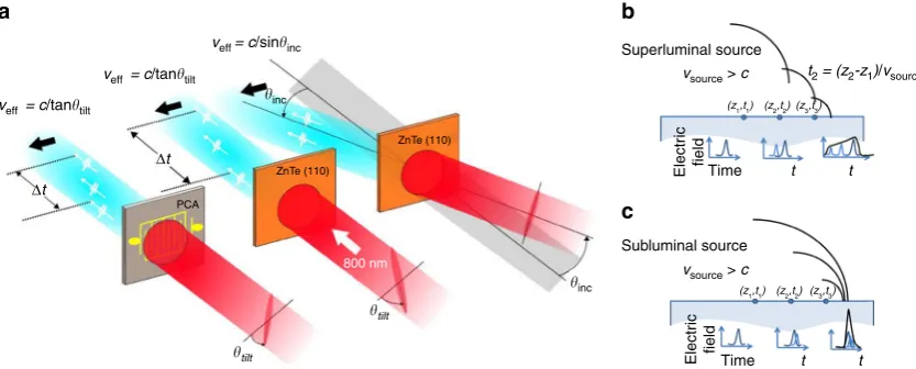
sub-luminal carrier wave, we exploit this group-to-phase conversion together with tilted optical pulse-fronts giving a controllable arrival-time delay exciting a planar terahertz source. Tilted pulse-fronts are generated through imaging of the pulse propagated from an optical diffraction grating. The optical wavefronts of the pulse remain orthogonal to the propagation direction, while there is a transverse time delay in the local energy content of the pulse. As shown in Fig. 1when impinging on a source plane (a non-linear χ(2) material or PCA) the delayed optical energy arrival produces an effective travelling wave source for the terahertz radiation. In the case of optical rectification, the preservation of wavefront direction orthogonal to propagation allows the one-dimensional pencil-beam χ(2) phase-matching conditions to be maintained independent of the pulse-front-tilt angle. The use of tilted pulse-fronts is central to obtaining an effective sub-luminal terahertz phase velocity. With pulse-front-tilt spanning the range 0ϕtilt<π=2 the effective surface optical group velocity (and hence terahertz phase velocity) can span 0<vopt;eff
group 1. As the optical
carrier wavefront remains travelling with normal angle of inci-dence with effective surface velocity voptϕ ;eff ¼ 1it cannot how-ever be exploited directly for acceleration. Although a simpler non-normal incident planar pulse front can also provide effective velocity control, such an arrangement is limited to velocities greater thanc; due to Snell’s law refraction of the pulse front on entry to the velocity reducing medium, this limitation of planar pulse-fronts holds even when the source is embedded in a material of refractive indexn>1.
Propagating evanescent waves. The excitation of the terahertz sources through tilted optical pulse fronts allows coupling of the optical energy into the source material at sub-luminal velocities. The outcoupling of the terahertz pulse from inside the source material is likewise subject to conditions of boundary continuity and refraction, and for conventional many-cycle electromagnetic waves the transition to sub-luminal source propagation is equivalent to meeting conditions for the critical angle of total internal reflection and post-boundary evanescent wave propaga-tion45. For the single-cycle pulses generated by optical rectifi ca-tion the classification of the post-boundary fields as non-propagating and exponentially decaying in amplitude is no longer appropriate. Conceptually describing the travelling wave source as a superposition of time delayed Huygens spherical waves the sub-luminal and super-luminal velocities, and
single-cycle vs. multi-single-cycle pulses, give rise to qualitatively different solutions for the propagating waves. For the super-luminal source (Fig.1b) a superposition of waves gives rise to a solution with a far-field distribution approximating an obliquely propagating plane-wave satisfying Snell’s law of refraction. For the sub-luminal case the Huygens waves of a single-cycle pulse cannot coincide, with the exception being vϕ=c for which they add coherently along the surface. For single-cycle pulses the process of constructive or destructive interference for Δϕ>2π does not arise and the exponential decay of thefield with distance from the surface associated with evanescent waves is supplanted with a slower 1/rdecay of the Huygensfields and a temporal stretching arising from the superposition of wavelets retarded in time by the sub-luminal source velocity.
To provide a detailed and quantitative picture of the single-cycle propagation from a sub-luminal source, finite difference time domain (FDTD) simulations have been undertaken (Methods section). An example of finite difference time domain calculation of emission from (and into) the surface under sub-luminal conditions is presented in Fig. 2a. In this example the terahertz radiation is generated only within the top 50μm layer of the dielectric; such a situation arises, for example, with a (110) oriented and χ(2) active ZnTe layer on a thicker inactive (100) oriented ZnTe substrate. Thinner sub-micron source layers are expected for photoconductive antenna. For thicker source regions spatio-temporal shaping of the source may also be required for high-efficiency generation, as discussed below for LiNbO3
sources. After an initial stage of propagation where the field is established in the region above the source plane, a stable pulse is obtained, travelling with a wavefront normal to the surface and with a velocity set by the effective source velocity. The normal-to-surface extention of thefield structure, which evolves over afinite time, is responsible for an apparent instananeous propagagtion of thefield across a gap in frustrated total internal reflection45,46. The physical connection to total internal reflection is described schematically in Fig. 2b, and is apparent in the numerically calculatedfield profiles of Fig.2a. A surface sub-luminal travelling source is analogous to that arising from a virtual planar wavefront arriving at an angle of incidence exceeding the critical angle. This virtual incident beam establishes a real beam propagating as if reflected, together with the sub-luminalfields propagating across the boundary into the vacuum region. The use of total internal refection and evanescentfields has been previously proposed for
Time ZnTe (110)
ZnTe (110)
800 nm PCA
Δt Δt
Electr
ic
field
t t
Superluminal source
t2 = (z2-z1)/vsource
(z
1,t1) (z2,t2) (z3,t3)
vsource > c veff = c/sininc
veff = c/tantilt
veff = c/tantilt
inc
tilt
inc
tilt Electr Time
ic
field
t t
Subluminal source
(z1,t1) (z2,t2) (z3,t3)
vsource> c
a b
c
Fig. 1Effective travelling wave concept, for both a nonlinear material and a photoconductive antenna.aFor a tilted pulse front the effective velocity is unbounded, while for an obliquely incident plane wave the effective source velocity is constrained to be greater thanc. Tilt and incident angles,θtiltandθinc, respectively, are those external to the source material. PCA: photoconductive antenna.b,cSchematic of Huygens waves (black) generating the propagating
[image:3.595.88.505.51.219.2]particle acceleration47,48. While the resultingfield structures and evolution is analogous to that expected in total internal reflection, our scheme does not rely on a real (terahertz) incident beam and avoids the associated obstacles of in-coupling of a pulse at a sub-critical angle.
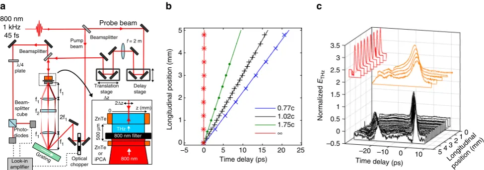
Observation of single-cycle sub-luminal propagation. Sub-luminal dispersionless terahertz pulses have been generated using the concepts of Fig.1, in both a large-area interdigitated photo-conductive antenna and through optical rectification in a (110)-cut ZnTe single crystal (see Methods section). The experimental configuration is shown schematically in Fig.3a. In both cases the optical pulse (group) front tilts were produced by a diffraction grating, with the diffracted pulse imaged onto the generation PCA or ZnTe crystal. The optical pump beam was incident normal to the generation plane. Temporal and spatial characterisation of the field was undertaken with electro-optic sampling with a 50 fs optical probe retro-reflected from the internal boundary of a separate ZnTe electro-optic detection crystal. The terahertz electricfield emitted from the source and propagated through air into the detection material effectively creates a birefringence in the detection crystal that temporally and spatially replicates the incident terahertz pulse, and this birefringence is observed
through the polarisation change of the optical probe (see Methods section). Figure3c shows pulse propagation measurements for a normal-incidence planar pulse front optical pump on a ZnTe emitter, with vTHz
eff ¼ 1, and measurements of vTHzeff c pulse
propagation in ZnTe and PCA sources. The tuneability from sub-to super-luminal propagation has been observed with temporal-spatial mapping of the pulse evolution undertaken for a range of pulse-front tilts, corresponding to effective velocities from 1.75c down to 0.77c. Measured world lines in ZnTe are shown in Fig.3b. We observe no significant pulse broadening or reshaping as a function of wave propagation along the surface; variations in intensity are attributable principally to the transverse intensity profile of the optical pulse providing the terahertz excitation.
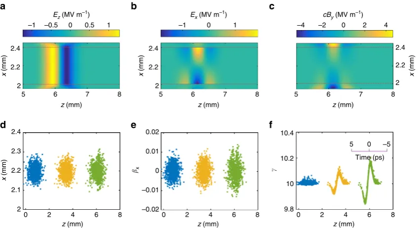
Application to particle acceleration and manipulation. Both PCAs and appropriately orientedχ(2)optical rectification sources will produce terahertz electricfields polarised in the plane of the source. With the field polarisation aligned in the direction of propagation of the travelling wave (the longitudinal direction) co-propagating charged-particle acceleration becomes possible. The longitudinal accelerating electric fields are accompanied by sig-nificant transverse electric and magnetic fields which arise through the spatial and temporal gradients of the terahertz source. For a relativistic particle with β≲c the magnetic deflecting force becomes comparable to the accelerating force. Additionally the transverse electric field necessary to satisfy the condition of vanishing electricfield divergence in the vacuum gap becomes comparable to the accelerating field temporally ahead and behind the region of acceleration. As in laser-dielectric acceleration schemes, and in conventional RF cavity acceleration, these deflection forces can be eliminated or reduced through imposing additional symmetry around the particle beam-axis. Here, we consider a two-dimension arrangement with sources located in a pair of z−y planes. This two-dimensional (2D) symmetric arrangement and the resultant field structure is similar to the total internal reflection scheme proposed by Frandsen et al.47and Pálfalvi et al.48. Figure4shows the electric and magnetic fields, calculated with FDTD modelling, in the vacuum gap between a pair of opposing sources embedded in dielectric media separated by 400μm (see Methods section). The longitudinal electric field sources Ez(x= ±250μm,z−βsct, t) are
localised in z−y planes with x= ±250μm, and propagate with source velocitycβs. The source velocity in these calculations was
βs=0.995, corresponding to velocity matching for a 5 MeV
electron beam. Due to cancellation of the transverse electric and magnetic fields in the symmetry plane of the source-pair, the deflection forces are minimal in a region of≈100μm around the central beam-axis, providing an acceleration potential bucket sufficient for injection of particle beams from conventional electron guns. The field structure produced from the opposing pair travelling sources is similar to that found within conven-tional RF accelerating structures, with the exception that the acceleratingfields and electromagnetic energy are co-propagating in synchrony with the charged particles rather than stored over the longer times and spatial extent in an accelerating cavity structure.
The results of modelling particle acceleration of a 5 MeV electron beam injected into the travelling source paired structure are shown in Fig. 4d–f. The particle dynamics has been determined through numerical solution of the relativistic Lorentz force equation, and include the electric and magnetic deflection forces (see Methods section). For the 2D arrangement of the source, the acceleration and deflection occur in thezandxaxes, withEy,Hx,Hz=0 by symmetry. The injected beam has aσt=1 ps root mean square (r.m.s.) pulse duration, and a transverse 2.8
2.6
2.4
2.2
x
(mm) 2
1.8
1.6
1.4
z (mm) z (mm)
n = 1 (z1,t1) (z2,t2) (z3,t3)
Sub-luminal source
Super-luminal source
Virtual reflected beam
0 1 2
10
5
0
Electric field strength (a.u.)
–5
–10 3
0 1 2
Vacuum Passive dielectric
Passive dielectric Active dielectric
3
Virtual incident beam inc refl
n > c / vsource
a b
c
Fig. 2Thefield evolution for a nonlinear source within a dielectric.
a,bFinite difference time domain calculations of the electricfield for a travelling source within a dielectric layer on a dielectric substrate. The terahertz source is only present within a 50μm active layer. The source velocity is greater than the speed of light within the dielectric, but less than the speed of light in vacuum. Time snap-shots are shown fora0.5 ps and
[image:4.595.47.289.48.338.2]phase-space emittance of 0.3 mm mrad, consistent with that obtainable from state-of-the-art RF photo-injectors1,49. We show the evolution of the particle distribution as the particles interact over ~7 mm with a peak accelerating gradient of 10 MV m−1and a 500 fs bipolar terahertz field representative of our LiNbO3
source to be described in the following section. Net energy gain of ~100 keV is obtained when injecting close to the peak phase of the accelerating field. In contrast to acceleration schemes using optical wavelengths, the approximately 100μm longitudinal dimension of the acceleration bucket ensures negligible phase slippage of electron bunches with a typical 10−3 energy spread, while the 100μm transverse dimensions of the acceleratingfield allow for the entire injected electron bunch to be captured and accelerated without transverse phase-space degradation.
MV m−1 field strengths for particle acceleration. The above measurements with interdigitated PCA and ZnTe optical rectifi -cation sources serve to illustrate the concept of a single-cycle source with longitudinal polarisation and sub-luminal dispersionless propagation. Neither of these optical to terahertz mechanisms or media are however capable of generating the multi-MV m−1field strengths sought for high-gradient relativistic particle acceleration. To achieve high field strengths the same travelling source concept has been adapted to work with a LiNbO3 nonlinear medium, a crystal that is capable of greater
than 100 MV m−1 field strengths50. A significant hurdle is encountered in using this established material for high-field terahertz generation, in that non-colinear propagation of terahertz and optical frequency waves is required to satisfy the terahertz and optical phase-matching51. For LiNbO3 the
optical group velocity exceeds the phase velocity of the generated terahertz radiation by a factor of approximately 2.5. As a consequence the terahertz radiation is generated in an obliquely propagating Cherenkov cone centred around the laser propagation axis. To allow efficient generation from a transversely extended optical beam a temporal-spatial correlation is introduced in the optical excitation pulse, with the correlation such that the locally produced Cherenkov cones add constructively to produce plane-wave emission in a specific
Cherenkov direction51,52. To provide aveff
ϕ <ctravelling source in LiNbO3, we have developed a scheme that maintains the standard
Cherenkov pulse-front tilt in one plane, while adding spatially dependent time delays in the orthogonal direction. As shown in Fig. 5, the LiNbO3 crystal is oriented with the standard
Cher-enkov tilt in thex,yplane, with the additional time delays in the x–zplane giving rise to a propagating source in the z-direction. While thez-direction delays could in principle be introduced by an optical staircase in the laser beam, here we achieve the con-tinuous rather than discretised propagation through introduction of an additional component of the pulse-front tilt in the x–z plane. Anx,ytilt of 24° corresponds to a propagation velocity of vzϕ¼c. We refer to this arrangement as a ‘double-tilt’ confi g-uration, although clearly each of the tilts are actually orthogonal components of a single (larger) pulse-front tilt projected into the exit plane of the LiNbO3crystal.
As constructed, the double-tilt arrangement seeks to maintain the terahertz generation efficiency enhancement that comes from transverse velocity matching to the Cherenkov angle. While such an enhancement will be expected to be maintained for a propagation delays introduced by a sufficiently coarse staircase delay optical element, the effect of a continuous delay from the orthogonal tilt component is less clear. We have carried out three dimensional FDTD simulations of the terahertz generation with single-tilt and double-tilt optical propagation and have confirmed that for our LiNbO3parameters the source-propagation tilt has a
negligible effect on the efficiency of the terahertzfield strength in the emission surface.
The double-tilt approach has been demonstrated through an optical arrangement similar to that employed for the ZnTe and PCA measurements. The combined pulse-front tilt was main-tained in the horizontal lab-frame horizontal plane, with the consequence that the transverse and longitudinal (effective propagation) directions, and the emission surface of the LiNbO3
were oriented out of the laboratory frame horizontal or vertical planes. As for the ZnTe and PCA measurements, a temporal and spatial mapping of the fields near the surface was obtained with EO sampling. The transverse intensity profile of the optical beam was also shaped with cylindrical telescopes so that following oblique incidence on the grating and projection onto the
out-of-Longitudinal position (mm)
0 1 2 3 4 5
Time delay (ps)
–5 0 10 15 20 25
0.77c 1.02c 1.75c
∞ 0
1 2 4 3 5 10 0 –10 –20 2.5
2 3.5
–0.5 1.5
1
0.5
0 3
Time delay (ps) f1
f1 f1
2f1
Grating
Beamsplitter
Beamsplitter
Optical chopper
Beam-splitter cube
Photo-diodes
Look-in amplifier
Delay stage Translation
stage
Δz
f = 2 m
f1
f2 λ/4 plate
0 z (mm)
800 nm THz
500
μ
m
ZnTe
800 nm filter
Probe beam
Pump beam
2Δz
b c
Normalized
ETHz
Longitudinal position (mm) 5
800 nm 1 kHz
45 fs
ZnTe or iPCA
a
Fig. 3Experimental measurements of the terahertz emission from a travelling source.aExperimental arrangement for the spatial and temporal characterisation of the terahertz pulse emitted from a ZnTe or interdigitated photoconductive antenna (iPCA) travelling wave source.bWorld lines of the terahertz pulse measured for a ZnTe source with differing pulse-front tilts. The data points are the time of the peak electricfield. The lines are linearfits to the data, and correspond to phase and group velocities from 0.77cto 1.75c.cExamples of the single-cycle terahertz pulse temporal profiles measured at positions in a plane parallel to the emitting surface. The longitudinal direction is defined as the direction of propagation of the travelling wave source. From
toptobottom, the pulses were generated by a planar wavefront optical pulse exciting a ZnTe emitter (veff=∞), andθ
tilt~ 45° pulse front exciting an PCA
[image:5.595.53.541.50.222.2]plane oriented crystal surface, the terahertz source dimensions were ~15 mm in the propagating source longitudinal direction, and 2 mm in the orthogonal transverse (Cherenkov matched) direction.
A temporal and spatial map of the terahertzfield 500μm from the LiNbO3 surface was measured with electro-optic sampling
and is summarised in the data of Fig. 6c–e. In this data set the single-cycle terahertz pulse is travelling at 0.98c, as determined through the time-delay of the peak longitudinal electricfield as a function of longitudinal position across the emitting surface. The laser pulse energy incident on the LiNbO3 terahertz generating
crystal was limited by the available laser system, and diffraction
grating and optical losses, to 600μJ. The transverse optical pulse shaping increased the optical pump energy density in the nonlinear LiNbO3 while maintaining the desired propagation
distance of approximately 10 mm. Absolute electricfield strength of a terahertz pulse can in principle be determined in EO sampling, through calibration of the EO signal into absolute polarisation rotation of the optical probe together with knowledge of the phase-matching and χ(2) nonlinear response of the EO detection crystal36. Where the terahertz and optical probe do not propagate collinearly in the detection crystal, the experimental response function is further subject to angular separation of the optical probe and nonlinear generated optical waves53. The physical separation of the optical waves in propagation from detection crystal to the photodiode detectors will give rise to an underestimate of the terahertz electric field strengths. The field reduction arising from this physical separation of optical waves is extremely challenging to objectively determine, and here we have instead provided a lower bound measurement of the electricfield, based on an assumption of collinear terahertz and optical probe waves. With our modest laser powers, we obtain a lower bound measuredfield strength of 0.20 MV m−1. Based on the established capability of LiNbO3we believe the true field strength could be
significantly higher, and that with improvements in laser system field strengths approaching 10 MV m−1may be readily obtained. Such acceleratingfield gradients would already be comparable to state-of-the-art superconducting accelerators such as the Eur-opean X-ray free-electron laser. Even higherfield strengths may be achievable through use of alternative nonlinear materials with demonstrated high-efficiency and high-energy generation cap-ability26–28.
Discussion
We have described and demonstrated a method for generating single-cycle terahertz pulses that propagate with an effective
sub-a b c
d e f
–1 –1 –4 –2 0 2 4
2.4
2.2
2
–0.5 0 0.5 1 0 1
2.4
2.2
2
2.4
2.2
2
2.4 0.02 10.4
10.2
10
9.8
0 2 4 6 8
0 2 4 6 8
0 2
5 6 7 8 5 6 7 8 5 6 7 8
4 6 8
0.01
0
–0.01
–0.02 2.3
2.2
2.1
2
x
(mm)
z (mm)
0
5 –5
Time (ps) z (mm)
z (mm)
z (mm) z (mm)
z (mm)
x
(mm)
x
(mm)
x
x
(mm)
cBy (MV m–1) Ex (MV m–1)
Ez (MV m–1)
Fig. 4Particle acceleration in a paired travelling source structure.a–clongitudinal electricfield (Ez) and transverse electric and magneticfield components
(Ex,Hy) att=18 ps for a 500 fs, bipolar terahertz source with peak longitudinalfield strength of 10 MV m−1generated in each crystal. Nonlinear dielectric
media are present atx<2.0 mm andx>2.4 mm, with a vacuum region in between. The vacuum/dielectric interfaces are marked withdotted lines. The nonlinear interaction in each crystal generates identical longitudinalfieldEzand opposite polarity transversefieldsEx,By.d–fTransverse position, angle and
energy respectively for 1000 electrons after acceleration in a 15 mm structure as a function of particle position in the bunch; particles enter the structure at 5.2 MeV/c, with 500 fs rms duration with 100μm rms diameter. Theblue,yellowandgreenparticle distributions correspond to those at times 0, 8.8 and 17.7 ps, respectively. For a 5 MeV beam energy with particle velocityβ/c=0.995, there is negligible velocity spread within the bunch, allowing the behaviour of shorter duration bunches to be inferred directly from the corresponding temporal slice in the particle distributions shown
Optical pulse Optical pulse
Teraher tz emission
Teraher tz emission
y
x z
y
x z
a b
Fig. 5Laser pulse-front tilt for terahertz generation in LiNbO3.aTraditional
[image:6.595.87.511.50.281.2] [image:6.595.49.287.383.540.2]luminal velocity, and without distortion of the single-cycle field profile during propagation. The electric field polarisation is constructed with a component in the longitudinal or propagation direction as required for acceleration of charged-particle beams. The transverse electric and magnetic fields that arise from the spatial and temporal gradients of the travelling source provide a focusing structure analogous to RF particle accelerators, but with a 1000-fold reduction in spatial scale. The 1 ps duration of the terahertz pulse is six orders of magnitude smaller than the μs cavity fill-time of conventional RF accelerating structures. The 106 reduction in the time-integrated energy content of the elec-tromagnetic field while maintaining field overlap with particle beams offers the potential for dramatic reductions in the power requirement of high energy particle accelerators. While the par-ticular demonstrations of single-cycle sub-luminal propagation presented here do not have the acceleratingfield strengths desired for immediate applications, sufficiently high field strengths are within reach of current sources. To be applied to acceleration of beams for ultrafast electron diffraction, energy gain of between 100 keV and 5 MeV is required, for bunch charges of less than 1pC, corresponding to5μJ of energy transfer to the electron beam; as context, it is noted that 900μJ, and GV m−1 terahertz sources have already been demonstrated26–28. Higher energy beams are required for the terahertz travelling source acceleration concept to be applied as a driver for free-electron lasers. A soft X-ray free-electron laser may be expected to operate with 1 GeV, 10 pC bunches, corresponding to a total beam energy of 10 mJ. While terahertz sources sufficiently energetic to provide this level of beam energy are not currently available, a principle benefit of our travelling source concept is that it is directly scalable with length, with no dispersion derived limitations. With rapid developments occurring in the efficiency and energy of nonlinear sources, a sub-luminal travelling terahertz source offers a pro-mising route to an all-laser driven free-electron laser.
Methods
Pump source. The Ti:Sapphire regenerative amplifier laser system used to generate terahertz radiation produced pulses with an energy of up to 2 mJ and a pulse duration of ~45 fs at a repetition rate of 1 kHz, with a central wavelength of 800 nm. Three different generation media were used; a 0.5 mm thick (110)-cut ZnTe crystal, a commercially-available interdigitated photoconductive antenna (Ter-aSED10, Laser Quantum Ltd.), and a 6% magnesium-oxide doped stoichiometric lithium niobate crystal. Further details of the interdigitated photoconductive antenna (PCA) can be found in ref.54.
Terahertz frequency generation with PCA and ZnTe. The interdigitated pho-toconductive antenna was biased with 25 V pulses at a repetition rate of 500 Hz
with a duty cycle of ~10% and photo-excited with 25μJ pulses at a repetition rate of 1 kHz from the regenerative amplifier laser system. The ZnTe crystal was pumped with 500μJ pulses and an optical chopper was used to reduce the repetition rate to 500 Hz for lock-in detection. Afilter was used to block the 800 nm pump light from being transmitted to the ZnTe detection crystal. Diffraction gratings with 1200 lines/mm and 600 lines/mm were used in a 4 f imaging arrangement (consisting of two 250 mm focal length cylindrical lenses) to produce a range of pulse-front-tilt angles within the generation medium. A 400 mm cylindrical lens was used to achieve an increase in the excitation energy density at the terahertz generation point without affecting the pulse-front-tilt angle.
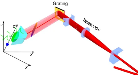
Terahertz frequency generation with LiNbO3. The lithium niobate crystal was pumped at 500 Hz with 600μJ pulses after losses from optics and the diffraction grating. A 1200 lines/mm diffraction grating was used to produce a pulse-front tilt of 43.8° and was imaged to the crystal using a single lens giving a magnification factor of 0.21 to give a total pulse-front tilt of 77.6° (63.8° inside the LiNbO3). A zero-order half-wave plate was used to rotate the polarisation of thefirst-order diffracted beam in order to match thez-axis of the lithium niobate crystal. The crystal was rotated by an angle of ~12.7° to give a phase-matching component of the tilt of 77.3° (63.0° inside the crystal) and a velocity generating component of 45.0° (24.2° inside), giving an expected velocity of approximately 1.0c. As shown schematically in Fig.7, The pump beam was shaped into an ellipse with the major axis aligned along the direction of travel of the generated terahertz wave. This was achieved using a telescope consisting of a two−50 mm focal length cylindrical lenses and a 250 mm spherical lens. These were used to produce a magnification factor of 5 in the vertical axis and 1/5 in the horizontal axis. The two cylindrical lenses were rotated about the pump propagation axis by ~3.6° in order to match the ellipse rotation to that of the lithium niobate crystal. The 3.6° rotation, along with projections onto the diffraction grating, produced afinal elliptical beam with a rotation of ~12.7°.
EO detection. In the PCA and ZnTe experiments, a 1 mm thick (110)-cut ZnTe crystal was used to detect the generated terahertz radiation with a separation of ~500μm between the generation medium and the detection crystal. In the LiNbO3 experiments, a 0.5 mm thick (110)-cut GaP crystal was used with a separation of ~300μm. In both cases, a balanced electro-optical detection scheme was used to measure the generated terahertz electricfields. The reflection of the probe pulse off of the inner surface of the detection crystal acquired a polarisation change which was proportional to the terahertz electricfield strength. The probe pulse was then separated into two orthogonal polarisation states using a polarising beam splitter and the intensities of each were measured using balanced photodiode detection scheme. A lock-in amplifier was used to measure the voltage change from the two photodiodes at the 500 Hz frequency of the pump pulse or the PCA bias voltage. The probe beam was focused to a≲100μm diameter spot at the detection crystal and its position could be translated horizontally and vertically, while maintaining a constant path length, using translation stages in order to measure the terahertz electricfields at different spatial positions over the crystal surface. A calibration of the probe beam translation stages was performed by attenuating the probe pulse and taking images of the probe beam displacements on the surface of the detection crystal using a CCD camera.
FDTD simulations and particle evolution. Thefinite difference time domain (FDTD) method is used to determine thefields as a function of time. The travelling bipolar terahertz source is embedded within the dielectric material (ϵ=9ϵ0) with velocityβs=1−5 × 10⁻³, matching aγ=10 (U≈5 MeV) electron beam velocity. 54
32 10
15 10 5 0 –5 –10 –0.5
0.5
0 1
a
Time delay (ps) –0.1
0 0.1 0.2
Peak time (ps)
–10 –5 0 10
Longitudinal position (mm)
0 1 2 3 4 5 6
b
c
ETHz
(MVm
–1
)
5
–5 0 5
Longitudinal position (mm)
Normalized
ETHz
Time delay (ps)
Fig. 6Measured terahertz pulse propagation in a plane parallel to the LiNbO3emitting surface.aElectricfield temporal profiles as a function of position
along the LiNbO3surface. Thefield strength is normalised to the peak strength at each measurement position.bExample terahertz electricfield profiles
[image:7.595.142.458.51.200.2]In line with the optical rectification generation process there is no magneticfield source and the electricfield of the source term is polarised purely in thez-direction, which also corresponds to our chosen source propagation direction. The spatial grid for the simulations of Figs.2and4is 5μm and the time step is 12 fs.
The particle phase-space evolution was obtained through numerical solution of the relativistic equation of motion
dβ dt¼
e mec
ffiffiffiffiffiffiffiffiffiffiffiffiffiffiffiffi
1j jβ2
q
Eþcβ´Bβ β½ E
½ : ð1Þ
A fourth-order Runge–Kutta algorithm was embedded within the FDTDfield evaluation algorithm, with particle velocities and positions updated at each time step of the FDTD code. The position and momentum of 1000 electrons were tracked as they progated through the double-sidedfield structure. The initial injected electron beam parameters are chosen to be representative of the VELA linear electron accelerator55with electron momentump=5.2 MeV/c (β=0.996).
Data availability. The data associated with the paper are openly available from the Mendeley Data Repository at:http://dx.doi.org/10.17632/5gd9vymhfb.1. Received: 4 August 2016 Accepted: 29 June 2017
References
1. Emma, P. et al. First lasing of an angstrom-wavelength free electron laser.Nat. Photon.4, 641–647 (2010).
2. Tanaka, H. et al. A compact X-ray free-electron laser emitting in the sub-angstrom region.Nat. Photon.6, 540–544 (2012).
3. Aicheler, M. et al. (eds)A Multi-TeV linear collider based on CLIC technology: CLIC Conceptual Design Report. Report No. CERN-2012-007(CERN European Organization for Nuclear Research, 2012).
4. Hill, M. E. et al. High-gradient millimeter-wave accelerator on a planar dielectric substrate.Phys. Rev. Lett.87, 094801 (2001).
5. Andonian, G. et al. Dielectric wakefield acceleration of a relativistic electron beam in a slab-symmetric dielectric lined waveguide.Phys. Rev. Lett.108, 244801 (2012).
6. Wang, D. et al. Interaction of an ultrarelativistic electron bunch train with a W-band accelerating structure: high power and high gradient.Phys. Rev. Lett.116, 054801 (2016).
7. Smirnova, E. I. et al. Demonstration of a 17-GHz, high-gradient accelerator with a photonic-band-gap structure.Phys. Rev. Lett.95, 074801 (2005). 8. Forno, M. et al. RF breakdown measurements in electron beam driven 200 GHz
copper and copper-silver accelerating structures.Phys. Rev. Accel. Beams19, 111301 (2016).
9. Thompson, M. C. et al. Breakdown limits on gigavolt-per-meter electron-beam-driven wakefields in dielectric structures.Phys. Rev. Lett.100, 214801 (2008). 10. Mangles, S. P. D. et al. Monoenergetic beams of relativistic electrons from
intense laser–plasma interactions.Nature431, 535–538 (2004).
11. Geddes, C. G. R. et al. High-quality electron beams from a laser wakefield accelerator using plasma-channel guiding.Nature431, 538–541 (2004). 12. Faure, J. et al. A laser–plasma accelerator producing monoenergetic electron
beams.Nature431, 541–544 (2004).
13. Hidding, B. et al. Generation of quasimonoenergetic electron bunches with 80-fs laser pulses.Phys. Rev. Lett.96, 105004 (2006).
14. Leemans, W. P. et al. GeV electron beams from a centimetre-scale accelerator.
Nat. Phys.2, 696–699 (2006).
15. Leemans, W. P. et al. Multi-GeV electron beams from capillary-discharge-guided subpetawatt laser pulses in the self-trapping regime.Phys. Rev. Lett.113, 245002 (2014).
16. van Tilborg, J. et al. Temporal characterization of femtosecond laser-plasma-accelerated electron bunches using terahertz radiation.Phys. Rev. Lett.96, 014801 (2006).
17. Debus., A. D. et al. Electron bunch length measurements from laser-accelerated electrons using single-shot THz time-domain interferometry.Phys. Rev. Lett.
104, 084802 (2010).
18. Buck, A. et al. Real-time observation of laser-driven electron acceleration.Nat. Phys.7, 543–548 (2011).
19. Heigoldt, M. et al. Temporal evolution of longitudinal bunch profile in a laser wakefield accelerator.Phys. Rev. ST Accel. Beams18, 121302 (2015).
20. Breuer, J. & Hommelhoff, P. Laser-based acceleration of nonrelativistic electrons at a dielectric structure.Phys. Rev. Lett.111, 134803 (2013). 21. Peralta., E. A. et al. Demonstration of electron acceleration in a laser-driven
dielectric microstructure.Nature91, 501 (2013).
22. Huang, W. R. et al. Toward a terahertz-driven electron gun.Sci. Rep.5, 14899 (2015).
23. Jamison, S. P. et al. Phase space manipulation with laser-generated Terahertz pulses.Proc. 35th Free Electron Laser Conf. 523–526 (2012)
24. Hebling, J. et al. Optical manipulation of relativistic electron beams using THz pulses. Preprint athttp://arxiv.org/abs/1109.6852(2011).
25. Nanni, E. A. et al. Terahertz-driven linear electron acceleration.Nat. Commun.
6, 8486 (2015).
26. Shalaby, M. & Hauri, C. P. Demonstration of a low-frequency three-dimensional terahertz bullet with extreme brightness.Nat. Commun.6, 5976 (2014).
27. Vicario, C. et al. Generation of 0.9-mJ THz pulses in DSTMS pumped by a Cr: Mg2SiO4laser.Opt. Lett.39, 6632–6635 (2014).
28. Vicario, C., Monoszlai, B. & Hauri, C. P. GV/m single-cycle terahertzfields from a laser-driven large-size partitioned organic crystal.Phys. Rev. Lett.112, 213901 (2014).
29. Wang, F., Adolphsen, C. & Nantista, C. Performance limiting effects in X-band accelerators.Phys. Rev. Accel. Beams14, 010401 (2011).
30. Kostin, D., Moeller, W.-D., Goessel, A. & Jensch, K. Superconducting accelerating module tests at DESY.Proc. of SRF2009, 180–184 (2009).
31. Cliffe, M. J., Graham, D. M. & Jamison, S. P. Longitudinally polarized single-cycle terahertz pulses generated with high electricfield strengths.Appl. Phys. Lett.108, 221102 (2016).
32. Deibel, J., Wang, K., Escarra, M. & Mittelman, D. Enhanced coupling of terahertz radiation to cylindrical wire waveguides.Opt. Express14, 279–290 (2006).
33. Grosjean, T. et al. Linear to radial polarization conversion in the THz domain using a passive system.Opt. Express16, 18895–18909 (2008).
34. Minami, Y., Kurihara, T., Yamaguchi, K., Nakajima, M. & Suemoto, T. Longitudinal terahertz wave generation from an air plasmafilament induced by a femtosecond laser.Appl. Phys. Lett.102, 151106 (2013).
35. Imai, R. et al. Terahertz vector beam generation using segmented nonlinear optical crystals with threefold rotational symmetry.Opt. Express20, 21896–21904 (2012).
36. Cliffe, M. J., Rodak, A., Graham, D. M. & Jamison, S. P. Generation of longitudinally polarized terahertz pulses withfield amplitudes exceeding 2kV/ cm.Appl. Phys. Lett.105, 191112 (2014).
37. Winnerl, S., Zimmermann, B., Peter, F., Schneider, H. & Helm, M. Terahertz bessel-gauss beams of radial and azimuthal polarization from microstructured photoconductive antennas.Opt. Express17, 1571–1576 (2009).
38. Winnerl, S., Hubrich, R., Mittendorff, M., Schneider, H. & Helm, M. Universal phase relation between longitudinal and transversefields observed in focused terahertz beams.New J. Phys.14, 103049 (2012).
39. Kan, K. et al. Radially polarized terahertz waves from a photoconductive antenna with microstructures.Appl. Phys. Lett.102, 221118 (2013). 40. Waselikowski, S., Fischer, C., Wallauer, J. & Walther, M. Optimal plasmonic
focusing on a metal disc under radially polarized terahertz illumination.New J. Phys.15, 075005 (2013).
41. Esarey, E., Sprangle, P. & Krall, J. Laser Acceleration of electrons in vacuum.
Phys. Rev. E52, 5443 (1995). Grating
Telescope
z z′
x
x′
Fig. 7Schematic arrangement for matching the transverse laser profile to a travelling source geometry in LiNbO3. The cylindrical lens telescope shapes
the laser transverse profile to an elongated elliptical beam on the LiNbO3
emission surface. The LiNbO3crystal is rotated with respect to the
[image:8.595.47.287.49.180.2]42. Wong, L. J., Fallahi, A. & Kärtner, F. X. Compact electron acceleration and bunch compression in THz waveguide.s. Opt. Express21, 9792–9806 (2013).
43. Jepsen, P. U., Jacobsen, R. H. & Keiding, S. R. Generation and detection of terahertz pulses from biased semiconductor antennas.J. Opt. Soc. Am. B.13, 2424–2436 (1996).
44. Ahn, J., Efimov, A. V., Averitt, R. D. & Taylor, A. J. Terahertz waveform synthesis via optical rectification of shaped ultrafast laser pulsess.Opt. Express
11, 2486–2496 (2003).
45. Mochan, W. L. & Brudny, V. L. Comment on“Noncausal time response in frustrated total internal reflection?”.Phys. Rev. Lett.87, 119101 (2001).
46. Carey, J. J., Zawadzka, J., Jaroszynski, D. A. & Wynne, K. Noncausal time response in frustrated total internal reflection?Phys. Rev. Lett.84, 1431 (2000).
47. Frandsen, B. R., Glasgow, A. A. & Peatross, J. B. Acceleration of free electrons in a symmetric evanescent waves.Laser Phys.16, 1311 (2006).
48. Pálfalvi, L., Fülop, J., Toth, G. & Hebling, J. Evanescent-wave proton postaccelerator driven by intense thz pulse.Phys. Rev. Spec. Top Accel. Beams
17, 031301 (2014).
49. Vinatier, T. et al. Performances of the Alpha-X RF gun on the PHIL accelerator at LAL.Nucl. Inst. Meth. A797, 222–229 (2015).
50. Hirori, H., Doi, A., Blanchard, F. & Tanaka, K. Single-cycle terahertz pulses with amplitudes exceeding 1 MV/cm generated by optical rectification in LiNbO3.Appl. Phys. Lett.98, 091106 (2011).
51. Fülöp, J. A., Pálfalvi, L., Hoffmann, M. C. & Hebling, J. Towards generation of mJ-level ultrashort THz pulses by optical rectification.Opt. Express19, 15090–15097 (2011).
52. Hebling, J., Almasi, G. & Kozma, I. Z. Velocity matching by pulse front tilting for large area THz-pulse generation.Opt. Express10, 1161–1166 (2002).
53. Walsh, D. A. et al. Role of misalignment-induced angular chirp in the electro-optic detection of THz waves.Opt. Express22, 12028–12037 (2014). 54. Beck, M. et al. Impulsive terahertz radiation with high electricfields from an
amplifier-driven large-area photoconductive antenna.Opt. Express18, 9251–9257 (2010).
55. Scott, D. J. et al. Vela machine development and beam characterisation. In
Proceedings of the 2015 International Particle Accelerator Conference1752–1755 (Joint Accelerator Conferences Website; 2015).
Acknowledgements
This work was supported by the United Kingdom Science and Technology Facilities Council [Grant No. ST/G008248/1]; the Engineering and Physical Sciences Research Council [Grant No. EP/J002518/1]; and the Accelerator Science and Technology Centre through Contract No. PR110140.
Author contributions
S.P.J. and D.A.W. proposed the concept and initial experiment, which was further developed by all. D.S.L. performed the experiments with help from D.A.W. and M.J.C., E.W.S. and S.P.J. performed the FDTD simulations. S.P.J. wrote the manuscript with contributions from all and revisions by D.M.G. and D.A.W., D.M.G. and S.P.J. supervised the project.
Additional information
Competing interests:The authors declare no competingfinancial interests.
Reprints and permissioninformation is available online athttp://npg.nature.com/
reprintsandpermissions/
Publisher's note:Springer Nature remains neutral with regard to jurisdictional claims in
published maps and institutional affiliations.
Open Access This article is licensed under a Creative Commons
Attribution 4.0 International License, which permits use, sharing, adaptation, distribution and reproduction in any medium or format, as long as you give appropriate credit to the original author(s) and the source, provide a link to the Creative Commons license, and indicate if changes were made. The images or other third party material in this article are included in the article’s Creative Commons license, unless indicated otherwise in a credit line to the material. If material is not included in the article’s Creative Commons license and your intended use is not permitted by statutory regulation or exceeds the permitted use, you will need to obtain permission directly from the copyright holder. To view a copy of this license, visithttp://creativecommons.org/ licenses/by/4.0/.


![2,4 Bis(furan 2 yl) 1,5 dimethyl 3 azabicyclo[3 3 1]nonan 9 one](data:image/gif;base64,R0lGODlhAQABAIAAAP///wAAACH5BAEAAAAALAAAAAABAAEAAAICRAEAOw==)