Development of Sensor less BLDC Motor Drive for PV System
Arnab Saha
Department of Electrical Engineering
Heritage Institute of Technology
Kolkata
India
Dipankar Saha
Department of Electrical Engineering
SDET-Brainware Group of Institutions
Barasat North 24 Parganas
India
Sarbojit Mukherjee
Department of Electrical Engineering
RCC Institute of Technology
Kolkata
India
Dr. Sumana Chowdhury
Assistant Professor
Department of Applied Physics
University of Calcutta
Kolkata
India
Abstract
Now-a-days Brushless DC motor is becoming alternate machine to Conventional DC motor or Induction motor due to its ease of operation and maintenance free operation. The speed control of this motor is easier than other motor. This has motivated the researchers for its development of drive. In the present work the authors develop the theory for logic sequence for BLDC sensor less drive and designed the hardware and implemented the logic sequences for two different mode of operation: one is 30 degree of rotor rotation and the other is 60 degree of rotation.
Index Terms:
Component, formatting, style, styling, insert. (key words)I. Introduction
II. Development of the Logic Sequence for Sensor Less Bldc Drive of Use
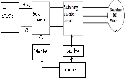
Fig 1 shows the block diagram for sensor less control of brushless dc motor. The motor used in experiment has three phase winding. A storage battery or a 24 volt dc source is used. Since the battery voltage is less than, the required voltage for rated operation of the motor boosting up is done by a Boost Converter.
Block Diagram of the Proposed BLDC Drive
Next a switching inverter circuit gives current to the BLDC motor according to rotate the rotor. A microcontroller based controller circuit has been designed. The boost converter converts this 24V dc voltage to 110V DC. The boost converter is based on MOSFET. The gate drive for switching this MOSFET is generated from the Controller circuit. DC 110 V is fed to the switching inverter circuit of the Brush less DC Motor. The switching inverter is based on MOSFET based three leg inverter bridge as shown in Fig 2. The predetermined gate drive control signal is generated from the controller circuit to drive the Misfits. The motor can be run in continuous mode by 30 degree firing scheme as well as 60 degree firing scheme.
Stator Double Circuit Winding
In this work, a BLDC motor with 24 coils with three phase 4 pole stator winding has been considered. So the number of coil per pole per phase is two. The stator winding thus can be considered two set of coils. For three phase such there number, two set of coils are star connected as depicted in fig 3. For phase A winding A1 A1’ are
start and finish of first set coil. A2 A2’ are the start and finish of second set coil of A phase. Similarly B1 B1’ , B2
B2’ and C1 C1’ and C2 C2’ are the respective set for B and C phase coils.
II a. Switching Sequence for 30 Degree Mode of Operation
To continuous run a brushless dc motor in case of 30 degree mode of operation at first one N pole is developed at A1 ( Fig 4 a).From the figure it is clear that to make a N pole there must be a clockwise circulating current around B2’ and C2 and similarly one clockwise current along B2 and C1’. Here one convention has been considered that dot current field is as anti clockwise direction and cross current field is as clockwise direction. So 30 degree switching means in every step the rotation of the stator pole is 30 degree. In the next sequence there must be clockwise current in c2 and A1’ and anticlockwise current in C1’ and A1 (Fig 4). Similarly the same action take place simultaneously for the rest of the rotation of the stator pole. Thus the sequence of operation is generated is tabulated in Table1.
II b. Switching Sequence for 60 Degree Mode of Operation
To continuous run a brushless dc motor in case of 60 degree mode of operation, at first one N pole at A1 is developed (Fig 5). So 60 degree switching means in every step the rotation of the stator pole is 60 degree. Hence in the next step A1’ and B1 are current carrying in clockwise direction and B2’ and A1 are carrying current in anticlockwise direction ( Fig 5). Similarly the sequence table can be developed (Table 2).
III Firmware Development
The PORTD of microcontroller is engaged for gate drive control signal for six number MOSFETS of the inverter circuit (Fig2). P0.1, P0.2, P0.3, P0.4, P0.5 and P0.6 gives gate signal for Q1, Q2, Q3, Q4, Q5 and Q6 respectively. The control signals are generated according to the sequence of operation for different mode of rotation. To limit the current through the winding Pulse Width Modulation ( PWM) scheme has been adopted. The gate signal is made on and off with a particular frequency so that the current through the winding does not exceed the rated current. Hence two timers are used. One is required to generate the switching signal and the other is for PWM generation.
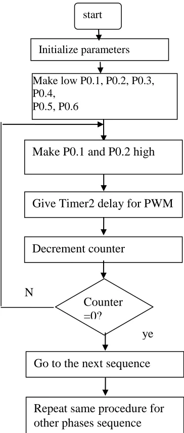
Two mode of operation ( 30 degree and 60 degeree ) flowchart of BLDC motor has been described. The flow chart is given in figure 6
Fig.6.Flowchart for BLDC Motor Control
IV.
Results and Discussion
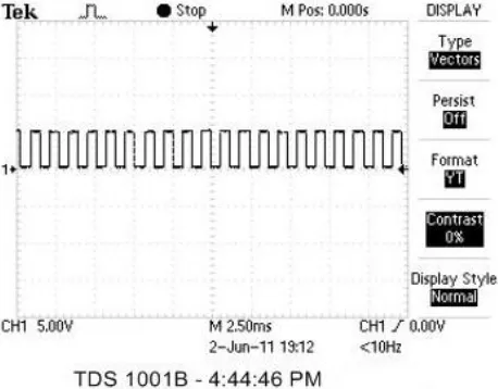
Fig 7 shows the pulse supplied to the gate of the individual MOSFET. The nature of the signal is PWM to reduce the average value of the current of the winding
Fig 7: PWM Gate pulse for MOSFETs
Make P0.1 and P0.2 high
Give Timer2 delay for PWM
Decrement counter
Counter
=0?
N
o
ye
s
Go to the next sequence
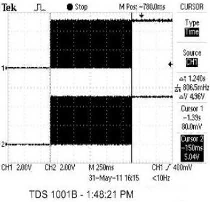
Fig 8 shows that simultaneous pulse supplied to the MOSFET 1 & 5. Both the signals are PWM.
Fig 8: Gate pulse For MOSFETs Q1 and Q5
Fig 9 shows the gate pulse transition from Q5 to Q6. A small delay is incorporated in between this transition to avoid shoot through fault depending on MOSFET characteristics.
Fig 8: Gate pulse For Transition form Q5 and Q6
Fig 10: Pulse train to Limit Winding Current
This is the voltage wave applied to the phase A. We are supplying a train of pulse at the gate of the MOSFET 1 & 6. That means in our star connected circuit we connect the path for the phase A & phase C. that’s why we are getting some current value at phase A & phase C. But there is nothing in the phase B.
References
‘Special electrical Machines’ by K.Venkataratnam
‘Permanent-Magnet & Brushless DC motors’ by T.Kenjo & S.Negamori.
Improved efficiency pumping system using permanent magnet brushless DC motor” by A Moussi & A Torki. ‘Permanent Magnet Motor Technology’ by Jacek.f.Gieras & Mitchell Wing
“Modeling, Simulation & implementation of Four-Switch ,Brushless DC motor drive based on switching function” by , Halvaei Niasar .
“180-Degree Commutation System of Permanent Magnet Brushless DC Motor Drive Based on Speed and Current Control To drive Brushless dc motor” by , Boyang Hu, Swamidoss Sathiakumar, Yash Shrivastava.
“The Effect of Magnet Size on Torque Characteristic of Three Phase Permanent Magnet Brushless DC Motor” by M. Norhisam, A. Nazifah, H. Wakiwaka & M. Nirei.