EFFECT OF TOOL NOSE RADIUS AND
CUTTING PARAMETERS ON TOOL
LIFE, SURFACE ROUGHNESS IN
TURNING OF GREY CAST IRON
Prasanna P Kulkarni1, Kiran J O2, Deeleepkumar S G3
1
Lecturer, Department of Mechanical Engineering, Sri Taralabalu Jagadguru Institute of Technology Ranebennur,
Karnataka, India
2
Assistant professor, Department of Mechanical Engineering, Sri Taralabalu Jagadguru Institute of Technology Ranebennur,
Karnataka, India ABSTRACT
In metal cutting industries peoples are trying to reduce the cost of the production by proper selection of inserts, tool geometry, and cutting conditions to obtain economical benefits. Tool nose radius has significant influence on tool life and surface finish. The aim of this research is to investigate the effect of tool nose radius under different cutting conditions and their effect on tool life, surface roughness. The measurement has been carried out by rough boring operation using grey cast iron cylinder liners at three cutting speed (Vc) and feed rate (f).
Depth of cut (doc) is kept constant at 2.5mm.Cutting tool used in this work is multilayer coated tool of nose radius 0.8mm and 1.2mm nose radius. Tool coated with titanium nitride (TiN) + titanium carbo nitride (TiCN) +Aluminium oxide (Al2O3) coating. The insert is designated with SNMG 120408. Cutting conditions used is
speed (Vc) 100m/min, 125m/min and 150m/min. Feed rate (f) 0.20mm/rev,0.23mm/rev,0.27mm/rev.Finally
results of the present work determine the appropriate parameter for increasing the tool life and surface finish for two different nose radius tools.
KEYWARDS: Tool nose radius, cutting parameters, Tool life, Surface roughness 1.INTRODUCTION
Cast irons are basically of iron and carbon. The cast iron contain between 2.14% to 6.67% carbon. The presence of high carbon content tends to make the cast iron brittle. Although cast iron is brittle, their properties can be improved by proper alloying and suitable heat treatment. The cast irons are cheaper than steels and can be more readily. Cast irons are low in ductility and therefore cannot be rolled, drawn or worked easily at room temperature. Most of the cast irons are not malleable at any temperature. But their melting temperature is considerably lower than those of steels and therefore can be melting readily. Fluidity of molten cast iron is very good and therefore can be cast into complicated shapes which can be later machined to final dimensions. Since casting is the only suitable process applied to these alloys, they are known as cast irons. Gray cast irons are the most widely used variety of cast iron amongst the various types. They are distinguished by the presence of graphite in the form of flakes (like fibres).Gray cast irons can be divided into different types based on the average length of the flakes in them. Gray iron is the most widely used, with annual production several times total of all other cast metals. It has excellent machinability, good wear resistance, and high vibration absorption. Gray iron is valued particularly for its ability to be cast into complex shapes at relatively low cost. Chromium occurs as carbide in iron and increases the tendency for the formation of white iron during solidification and the retention of a higher combined carbon in the solid state. This increases the wear resistance of the iron.
According to some authors, it is demonstrated that the cutting tool edge geometry significantly influences many fundamental aspects such as cutting forces, chip formation, cutting temperature, tool wear, tool-life and characteristics like surface roughness and surface damage [1, 3]. Several researchers are claimed that, in the manufacturing industry is constantly striving to decrease its cutting costs and increase the quality of the machined parts as the demand for high tolerance manufactured goods is rapidly increasing. The increasing need to boost productivity, to machine more difficult materials and to improve quality in high volume by the manufacturing industry has been the driving force behind the development of cutting tool materials [9].
Literature of the coated tools with variation in cutting parameters and tool geometry has been discussed in the following paragraphs. According to Thamizhamanii(2006) reported that major challenge of modern machining industries is focused mainly on the achievement of high quality, in terms of work piece dimensional accuracy, surface finish, high production rate, less wear, on the cutting tools, economy of machining in terms of cost saving and increase the performance of the product with reduced environmental impact [7]. During turning one of the most important factors is tool wear whether it is soft or hard work pieces. The primary tools wear are classified as flank wear, crater wear and nose wear, are important wear which will affect the smoothness of the product, cost of operation and performance. Authors proved that tool wear is caused by the normal load generated by interaction between tool work piece and tip of the tool. Tool wears which results in tool substitution, is one of the most important economical penalties, so it is very important to minimize tool wear, and optimizing all the cutting parameters like depth of cut, cutting velocity, feed rate and cutting fluids [8].Author Khan et al. investigated that at a high cutting speed tool wear occurs more intensively and causes the requirement of frequent tool changing. Again, tool changing time increases machine downtime and reduce the productivity of machining [5] Users expect to have more and more productivity in their machining processes (high removal rate of work-material) and low wear of their cutting tools (long tool life). These demands require major improvements in the design of cutting tools: new substrates, new coatings, cutting tool geometry and materials etc.According to tool manufacturers, the manufacturing procedures of their cutting tools, especially the micro-geometry preparation (cutting edge etc.), have a major influence on their performance and on their reliability [6]. The authors reported that there exists an optimum cutting edge radius that minimizes tool stresses, especially within the coating layer, and prolongs the tool life .The authors claimed that the cutting edge radius increasing can lead to a longer tool life. Rech et al. investigated the effects of edge radius of PVD coated tools upon chip formation and tool stresses in orthogonal cutting of steel. [4]. Literature of cutting edge effects on coating tool performance is limited. Bouzakis et al. (2003) studied the wear behavior of physical vapor deposition (PVD) coatings on cemented carbide inserts with various cutting edge radii in milling. [2]
Any change in the cutting feed leads to a corresponding change in the cutting temperature, so the cutting feed should influence the tool wear rate. As such, there are three basic cases: (a) if the current machining takes place using a relatively low cutting speed so that the cutting temperature is lower than the optimal cutting temperature, then an increase in the cutting feed leads to a decrease in the tool wear rate; (b) if the current machining takes place using an “average” cutting speed so that the cutting temperature passes its optimum with an increase in the cutting feed, then the relation hs=(f) has a distinctive minimum. In other words, increasing the cutting feed until the cutting temperature remains below the optimal cutting temperature reduces the tool wear rate, while any further increase would increase this wear rate; (c) if the current machining takes place using a high cutting speed, i.e., when the cutting temperature is higher than the optimal cutting temperature, then any increase in the cutting feed should lead to an increase in the tool wear rate.
There are many parameters that have effect on tool life and surface roughness in machining of various materials. From the literature it is clear that in order to enhance the productivity in terms of tool life, surface finish with variation of cutting parameters, tool materials and tool geometry. It was evident by some research papers observation that, it is not clear how the cutting edge effect on the machining performance using multilayer coated tool during machining of grey cast iron cylinder block which is having grooves (interrupted portion) shown in fig 1. In the present work it reveals that many investigations to improve the tool life and surface finish using multilayer coated tool with different nose radius tool. Coated tools of nose radius 0.8mm and 1.2mm were used in this work. Considerable experimental work carried out during machining grey cast iron cylinders used in automotive industry. During machining of grey cast iron it was observed that tool wear is due to the hard and brittle property of the work material. At different speed and feed rate investigated tool life and surface roughness. Finally it has been investigated the optimized cutting conditions to enhance the tool life and surface finish using two different nose radius tools.
2. Experimental Details
Alloying E % w
a Elements wt 3
Table-1 Ch
Fig: 2 a) Carbid C
.00 – 3.50 1
hemical compositi
Fig: 1 Work p
de inserts b) Mach Si 1.90 – 2.20
ion of grey cast iro
piece (Cylinder lin
b hining process c) S
Mn 0.45 – 0.65
on (Cylinder liner)
ner)
urface roughness t Cr 0.30– 0.50 0
testing process Ph Su 0.10 0.05
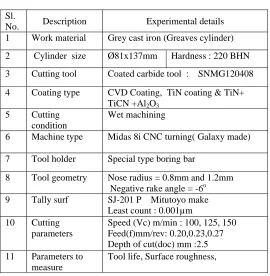
Table – 2 Experimental details
3. Results and Discussions
Results of the experiments were analyzed with different experiments carried out on grey cast iron with different cutting parameters for two different nose radius tools. Influence of the cutting parameters and nose radius has been determined experimentally. In order to identify the influencing of parameters on the tool life and surface roughness and productivity which have been discussed in the following paragraphs.
3.1 Effect of Nose radius and Process Parameters on Tool life
3.1.1 Effect of feed rate on tool life
The comparison of the tool life with cutting velocities and feed rate when using 0.8mm and 1.2mm nose radius tool shown in table 3.Figure 3 shows that the tool life decreased with an increase in the feed and cutting speed. As the feed rate increased to 0.27mm/rev which leads to decreased in tool life in both tools. Tool wear is due to the rubbing of the tool along the mechanical surface, and also at high speed and feed rate excess heat generated in tool chip interface which results corner burnt. Whereas at combination of low feed rates and speed it produced the longest tool life. At feed rate 0.2mm/rev and 0.23mm/rev tool life is in increasing trend, this is due to the less friction and vibration between tool and work surface. Also at low feed and speed it required minimum stress to remove the material from the work surface which results increased in tool life. From the experimental results it was noticed that at speed of 125m/min longest tool life was observed that is 85min to 95 min in each tools. This can be attributed to decreased work hardening with increasing thermal softening of the work surface. Also it was proved that if the current machining takes place using an average cutting speed so that the cutting temperature passes its optimum temperature and vibration with an increase in the cutting feed. From figure 4 tool life was increased in 1.2mm nose radius tool compare to 0.8mm nose radius tool. According to experimental results it was observed that at low feed rate of 0.2mm/rev tool life is 90min to 93min where using the speed in the range o 100 to 125m/min.This can be explained while machining grey cast iron which produces continuous chips and high withstanding capacity under impact load and feed force in larger radius tool. Cutting with large nose radius increases the tool edge strength and prevents the chipping of the cutting edge and impact strength to the cutting edge.
Sl.
No. Description Experimental details 1 Work material Grey cast iron (Greaves cylinder)
2 Cylinder size Ø81x137mm Hardness : 220 BHN 3 Cutting tool Coated carbide tool : SNMG120408 4 Coating type CVD Coating, TiN coating & TiN+
TiCN +Al2O3
5 Cutting condition
Wet machining
6 Machine type Midas 8i CNC turning( Galaxy made) 7 Tool holder Special type boring bar
8 Tool geometry Nose radius = 0.8mm and 1.2mm Negative rake angle = -6o 9 Tally surf SJ-201 P Mitutoyo make
Least count : 0.001µm 10 Cutting
parameters
Speed (Vc) m/min : 100, 125, 150 Feed(f)mm/rev: 0.20,0.23,0.27 Depth of cut(doc) mm :2.5 11 Parameters to
measure
0 10 20 30 40 50 60 70 80 90 100
0.2 0.23 0.27
Tool
l
ife
(
m
in
ut
e)
Feed (mm/rev)
Tool life
100 m/ min 125 m/ min 150 m/ min
0 20 40 60 80 100
0.2 0.23 0.27
T
ool lif
e
(m
in
ut
e)
Feed (mm/rev)
Tool life 100 m/ min 125 m/ min
150 m/ min
Table- 3 Experimental results for Tool life
Fig: 3 Feed rate vs Tool life result for 0.8mm nose radius tool Fig: 4 Feed rate vs Tool life result for 1.2mm nose radius tool
In metal cutting, however, tool wear is a dominant concern because process conditions are chosen to give maximum
Productivity, often resulting in tool life measured in minutes. Central to the problem are: high contact temperatures at the tool–chip and tool–workpiece interfaces, which lead to softening of the tool material and promotes diffusion and chemical (oxidation) wear; high contact pressures at these interfaces and sliding of freshly formed (juvenile) surfaces of the work material layers promote abrasive and adhesion wear [12], cyclic nature of the chip formation process, which can cause cracking due to thermal fatigue. According to results it was evident that large edge radius is suitable for brittle materials like cast iron with continuous chips also suitable for machining of interrupted parts due to its high impact strength.
Sl. No
Speed (Vc),
m/min
Feed (f ), mm/rev
Depth of cut (doc), mm
Tool life(T), Min Nose radius
0.8mm 1.2mm
1 100 0.27 2.5 61 82
2 100 0.23 2.5 73 93
3 100 0.2 2.5 89 98
4 125 0.27 2.5 51 59
5 125 0.23 2.5 51 63
6 125 0.2 2.5 85 93
7 150 0.27 2.5 28 32
8 150 0.23 2.5 57 63
3.2 Effect of Nose radius and Process Parameters on Surface roughness
Table- 4 Experimental results for Surface roughness
3.2.1 Effect of feed on surface roughness
Tool nose radius has a significant contribution that affect on the surface roughness. Fig 5 and Fig 6 shows that the variation in surface roughness values with increasing feed rate when using two different nose radius tools. Surface roughness is another important index of machinability as performance and service life of the machined component are often affected by its surface finish, nature and extent of residual stress and presence of surface or subsurface micro cracks. During turning cylinder liner using two different radii tool, results indicate that at high cutting speeds the smooth surfaces finish were produced in low feed rates. Surface roughness is high at feed rate 0.27mm/rev in each speed. It is due to rapid movement of the tool on work surface produces high friction which leads high temperature causes rubbing and feed marks on work surface. It was observed that least surface roughness that 2µm to 2.3 µm at higher speed 150m/min and low feed rate value of 0.2mm/rev when using 1.2mm nose radius too. A larger nose radius tool produces smoother surface finish compare to small nose radius tool in all three cutting conditions. It was evident by experiment that feed rate is the significant factor effect on the surface quality of the machined surface. It can explained that tool with larger nose radius with stand damping (vibration) and area of contact is more with work surface which can be easily absorb high cutting force and vibration at high speed and feed rate.
Sl. No
Speed (Vc),
m/min
Feed (f ), mm/rev
Depth of cut (doc), mm
Surface roughness (Ra), µm
0.8mm Nose radius
1.2mm Nose radius
1 100 0.27 2.5 3.80 3.10
2 100 0.23 2.5 3.2 2.8
3 100 0.2 2.5 3 2.55
4 125 0.27 2.5 3.1 2.69
5 125 0.23 2.5 2.8 2.50
6 125 0.2 2.5 2.7 2.4
7 150 0.27 2.5 2.63 2.5
8 150 0.23 2.5 2.5 2.30
0 0.5 1 1.5 2 2.5 3 3.5 4
0.2 0.23 0.27
Sur fac e r ough ness (m icr ons) Feed (mm/rev) Surface roughness
100 m/ min
125 m/ min
150 m/ min
1 1.5 2 2.5 3 3.5
0.2 0.23 0.27
S ur fa ce r o u g hn es s( m icr o n s) Feed (mm/rev) Surfe roughness
100 m/ min
125 m/ min
150 m/ min
Fig: 5 Feed rate vs Surface roughness result for 0.8mm Fig: 6 Feed rate vs Surface roughness result for 1.2mm nose
nose radius tool radius tool
Also multilayer coated tool with large radius tool having a wear resistance property due to high hardness of the tool and impact strength of the tool which can be easily absorb the impact load at interrupted portion in cylinder liner. The results shows that with increasing the nose radius and decreasing the feed rate surface roughness value decreased.
4. Conclusions
Based on the results of the experimental investigation the following conclusions presented regarding tool nose radius. The effect of process parameters and nose radius on the tool life, surface roughness has been investigated with the help of different experimental work.
1. From the experimental results, it is evident that the least surface roughness was achieved at higher speed rates in larger radius tool than smaller radius tool.
2. The least tool life was achieved at high feed rate of 0.27mm/rev with two different nose radius tools. 3. At high cutting speed and feed rate tool life is increased in 1.2mm nose radius tool compare to 0.8mm nose
radius tool.
4. Surface roughness is increases with increasing feed rate with two different nose radius tools. 5. The larger nose radius tool has a strong potential in wet machining of grey cast iron.
6. Performance of larger nose radius tool is superior compare to smaller radius tool in terms of tool life, surface finish in machining of interrupted parts.
References
[1] Altin, A., Gokkaya, H., and Nalbant, M., (2007) “The effect of cutting speed and cutting tool geometry on machinability properties of
nickel base Inconel 718 super alloys”, Materials and Design, Vol. 28, No.4, Pp.1334-1338.
[2] Bouzakis, K.-D., N. Michailidis, G. Skordaris, S. Kombogiannis, S. Hadjiyiannis, K. Efstathiou, G. Erkens, S. Rambadt, I. Wirth
(2003). “Optimization of the Cutting Edge Roundness and Its Manufacturing Procedures of Cemented Carbide Inserts, to Improve Their Milling Performance after a PVD Coating Deposition, “Surface and Coating Technology, Vol. 163-164,pp.625-630
[3] Hughes J. I., Sharman A. R., and Ridgwayk, C. (2006) “The effect of cutting tool material and edge geometry on tool life and
workpiece surface integrity”, Proceedings of the Institution of Mechanical Engineers. Part B. Journal of Engineering Manufacture, Vol. 220, No.2, pp.93-107.
[4] (Rech 2004). Rech, J., Y.-C. Yen, H. Hamdi, T. Altan, K.D.Bouzakis (2004). “Influence of Cutting Edge Radius of Coated Tool in
Orthogonal Cutting of Alloy Steel.” Materials Processing and Design: Modeling, Simulation and Applications, NUMIFORM 2004, pp. 1402-1407.
[5] Khan, A.A., A.N.R. Zuraida, and Y. Izayusmati, 2002. High Speed Milling of Cast Iron and Medium Carbon Steel using Cermet and
Carbide Tools. Proceeding of the BSME-ASME International Conference on Thermal Engineering, 31 December 2001, 2 January 2002, Dhaka, Bangladesh, pp. 711-717.
[6] Joel, RECH. (2005) “Cutting edge preparation and surface issues”, HSS forum International conference “smart solutions for metal
cutting” Aachen, 2-3 Feburary, pp.1-12.
[7] Thamizhmanii S., Hassan S., 2006. Analyses of roughness, forces and wear in turning gray cast iron, journal of Achievements in
Materials and Manufacturing Engineering, VOLUME 17, ISSUE 1-2 July-August.
[8] Thamizhmnaii, S., Bin Omar B., Saparudin S., Hasan, S. "Tool flank wear analyses on martensitic stainless steel by turning".
International scientific journal, V32, ISSI, Malaysia,(2008),PP41-44.
[9] Wall bank, J., “Development in tool materials advanced machining for quality and productivity”, Proceedings of the second
international conference on behavior of materials in Machining. York, UK, Nov 14-15 (1991).
[10] Kronenberg MN (1966) Machining science and application: theory and practice for operation and development of machining
processes. Pergamon Press, Oxford, UK.
[11] Gorczyca FE (1987) Application of metal cutting theory. Industrial Press, New York.
[12] Olson M, Stridh B, Söderberg S (1988) Sliding wear of hard materials—the importance of a fresh counter material surface. Wear