http://www.sciencepublishinggroup.com/j/ae doi: 10.11648/j.ae.20190302.17
Regulation and Thermal Compensation of Continuous
Forced Convection Indirect Solar Dryer for the Drying of
Agricultural Products: Maize, Mahogany Nuts, Shea Nuts,
By-products Derived from the Processing of Mango
Madjoyogo Herve Sirima
1, Betaboale Naon
2, Paul Wambua
31Mechanization Department, Institute of Research in Applied and Technological Sciences, National Center for Scientific and Technological
Research, Ouagadougou, Burkina Faso
2Study and Research Group in Mechanics, Energetics and Industrial Technics, University Institute of Technology, Nazi Boni University,
Bobo – Dioulasso, Burkina Faso
3
Industrial Engineering Department, Distant Production House University, Kigali, Rwanda
Email address:
To cite this article:
Madjoyogo Herve Sirima, Betaboale Naon, Paul Wambua. Regulation and Thermal Compensation of Continuous Forced Convection Indirect Solar Dryer for the Drying of Agricultural Products: Maize, Mahogany Nuts, Shea Nuts, By-products Derived from the Processing of Mango. Applied Engineering. Vol. 3, No. 2, 2019, pp. 119-124. doi: 10.11648/j.ae.20190302.17
Received: July 13, 2019; Accepted: August 14, 2019; Published: September 18, 2019
Abstract:
In this work; we were interested in the respect of the drying parameters, namely the recommended temperature range and the extraction of the moisture content during the drying of maize, mahogany nuts, shea nuts or by-products resulting from the processing of the mango. The thermal analysis of the drying system leads us to develop a system of regulation and thermal compensation in order to avoid the calcinations of the finished product and to respect the physicochemical parameters of the material. It must be emphasized that there are several agricultural products and their physicochemical parameters are not the same. Therefore the temperature ranges will be selected from the control system and compensation while taking into account the quality of said products. Note also that this study is conducted in a Sahelian country where sunshine is important and it becomes interesting to proceed to a regulation and a thermal compensation. To do this, we designed the control system and thermal compensation while taking into account the drying temperature.Keywords:
Thermal Regulation, Thermal Compensation, Solar Drying, Agricultural Products and by-Products, Temperature, Humidity1. Introduction
One of the primary means of drying agricultural produce is direct sun exposure, but this method is not without drawbacks due to bad weather. Such bad weather has adverse effects on the quality of these agricultural products.
Drying with solar driers is one of the best alternatives to maintain the intrinsic qualities of dried agricultural products [2-3]. This drying system also recommends the respect of certain parameters so as not to harm the products during drying [4-7].
In view of the foregoing, the regulation of these parameters becomes a need during the drying process as well as the compensation of the coolant for drying.
This work aims to develop a device for regulating and thermally compensating the indirect forced convection solar dryers.
2. Devices Description for Regulating the
Drying System [1, 8-13]
2.1. The Temperature Sensor
signal resulting from the variation of resistance. A microprocessor controls and exploits the electrical signal. The current temperature of the system is displayed by LED's directly on the electronic box. The microprocessor and the display simplify the use considerably [1].
Figure 1. Thetemperature sensor.
2.2. The Solenoid Valve
The solenoid valve will be used to regulate the flow and pressure of the heat transfer fluid and is controlled by an electromagnet.
Figure 2. Solenoid valve with pilot control integrated, membrane not coupled3/8to2.
2.3. The Relief Valve
The relief valve allows the protection of the equipment against the effects of overpressure when the supply of the installation is from a pressure much higher than the maximum operating pressure.
Figure 3. Relief valve.
3. Thermal Sizing of the Heating System
The drying temperature of the products is of the order of Ts∈[ θ °C; θ′ °C] with θ °C θ′ °C while taking into account calcination.
The volume of water extracted per hour during the drying time is obtained by the following formula:
Vwater=mh.(%e-r−%water)/(1000−%water)/Ts
a)mh: Product mass when wet, ie1kg;
b)%water: Moisture content of the product when wet, 95%;
c)%e-r: Recommended moisture content for the finished
product, 12%;
d)Ts: Drying time depending on the quality of the material.
The flow rate of the coolant is determined by the blower or the air compressor which is of the order:
Dfc=12dm3/mn
i. Qp1=Ma. Cpa.(Tas−Tae)–Σ(convective losses of the
ducts)In case it is the solar source, only, that works. Qp1: Power produced by the solar source in Joule (J)
Ma: Mass flow rate of air in kg/s
Cpa: Thermal capacity of the air in J/kg.°C
Tas: Air temperature at the outlet of the generating source
(Solar thermal).
Tae: Air temperature at the input of the producing source
(Solar thermal).
ii. Qp2=RI2. Tr-Σ(convectivelossesoftheducts) In case it is
the heating resistor, only, that works.
Qp2: Power produced by the source of the heating
resistance in Joule (J)
R: System resistance in ohm (Ω)
I: Intensity crossing the resistance in ampere (A) Tr: Heating time(s).
Qp=Qp1+Qp2=Ma. Cpa.(Tas−Tae)+RI2. Tr- Σ (convective
losses of the ducts)In case both sources are recommended. The flow of heat received by the material is:
Φ=λl.( ).(Um. Dl.( ))m. S. (Tpext–Tpint)carΦ=h. S. (Tpext–Tpint)
The temperature required for drying which is of the order of Ts will be programmed from a display. But this
temperature is obtained before hand by the formula:
l.( ).(Um. Dl.( ))m. S.(Tpext–Tpint)=Ma. Cpa. (Tas−Tae)+RI2.
Finally, we get the following formula:
Tpint=Tpext–[Ma. Cpa.(Tas−Tae)+RI2. Tr–Σ(convectivelossesoftheducts)]/ l.( ).(Um. Dl.( ))m. S
Figure 4. Materialization of the different flows in the ducts.
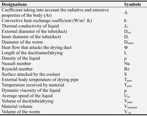
Table 1. Identification of the different parameters.
Designations Symbols
Coefficient taking into account the radiative and emissive
properties of the body (Ar) A
Convective heat exchange coefficient (W/m². K) h
Thermal conductivity of liquid l
External diameter of the tube(duct) Dext
Inner diameter of the tube(duct) Di
Diameter of the worm Darbre
Heat flow that attacks the drying duct Φ
Length of the duct(tunnel)drying L
Density of the liquid
Nusselt number Nu
Reynold number Re
Surface attacked by the coolant S
External body temperature of drying pipe Tpext
Temperature received by material Tpint
Dynamic viscosity of the liquid
Average speed of the liquid Um
Volume of duct(tube)drying Vpipe
Material volume Vmaterial
Volume of the worm Vvsf
4. Results and Discussion
The heating system used in this study is a combined system of solar thermal and heating resistance that will serve to over heat the compressed air produced. In this system the heating resistor will serve as compensation or replacement in case of failure to reach the ideal temperature between [θ°C;θ′°C] with θ°C θ′°C.
The heat transfer fluid from the solar thermal interconnection system-heating resistor will be regulated according to demand.
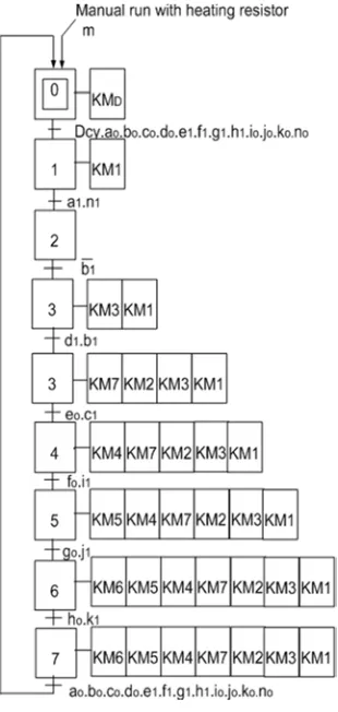
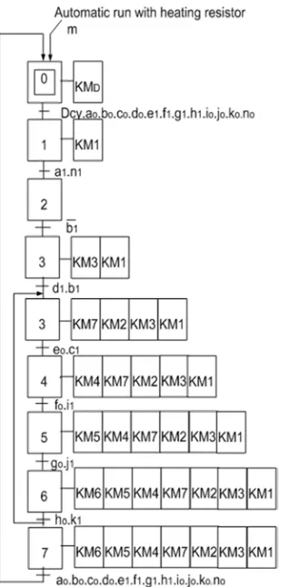
To do this, the recommended temperature range [θ°C;θ′°C] is programmed on a display. This display will be in connection with a temperature sensor and a motorized valve. The temperature sensor installed in the chamber of the drying chamber will send information on the display regarding the heating state of the drying chamber. The display will control the opening of the motorized valve to allow the passage of the material when the temperature range [θ°C;θ′°C] is reached, and the closing of said valve in case the temperature will be above said desired range in order to avoid the calcinations of the product (see Figures 5 & 6) since we are in the case of a continuous indirect convection dryer with forced convection.
In addition, another probe will control the startor stop of the heating resistor if the temperature is below respectively above the desired range (see Figures 5 & 6).
Table 2. Actions and commands.
Actions Commands
Heat transfer fluid production KMD
Sends heat transfer fluid into the heating chamber KM1
Continuous drying of the product KM2
Starting the heating resistor after time t to compensate for
the deficiency KM3
Actions Commands
Closure VC2 KM5
Closure VC3 KM6
Hopper valve closure KM7
Table 3. Informations et sensors.
Informations Sensors
Initialization m
Presence heat transfer fluid n1
Absence heat transfer fluid n0
Open valves a1
Closed valves a0
Drying temperature reached b1
Drying temperature not reached b0
Products or by-products being dried c1
Products or by-products not in the course of drying c0
Heating resistance running to compensate for the insufficiency d1
Heating resistance at standstill d0
Closed hopper valve e1
Open hopper valve e0
Chamber valve1 (VC1) closed drying f1
Chamber valve1 (VC1) open drying f0
Chamber valve2 (VC2) closed drying g1
Chamber valve2 (VC2) open drying g0
Chamber valve3 (VC3) closed drying h1
Chamber valve3 (VC3) open drying h0
Material presence at VC1 level i1
Material absence at level VC1 i0
Material presence at VC2 level j1
Material absence at level VC2 j0
Material presence at VC3 level k1
Absence of material at the level of VC3 k0
Figure 6. Grafcet manual and automatic controls with heating resistor.
We did not speak specifically about the pressure and the flow rate of the coolant because they depend on the blower or the air compressor used.
Note also that the recommended pressure will be of the order of 10 bars and the flow of said heat transfer fluid will be of the order of 12dm3/min.
In our design there are three stages of drying ducts, so we will have probes for each compartment. This will allow us to correctly follow the behavior (Temperature in degrees Celsius and the pressure in bars as a function of time in minutes) of the different drying ducts.
5. Conclusion
The thermal analysis of the continuous forced convection indirect solar dryer has led to the development of a rigorous system for monitoring temperature and humidity, which are the crucial parameters in the drying process.
The thermal regulation of the drying system also makes it possible to avoid the calcinations of the finished product and to respect the recommended quality. The direct connection of this drying system to the mango processing line at the plant and processing plant levels will reduce production costs and the regulation of the coolant.
The forced convection indirect solar dryer would perform better in the northern, Sahel and central regions (Burkina Faso) as solar rays are more intense in these areas. But the disadvantage at this level will be the acquisition of the raw material which is available in quantity only in the western part of the country.
References
[1] IFM electronic 7844X Made in Germany Edition 2, 2011, 311 pages.
[2] Reports of the 2015, 2016, 2017 year campaigns of the Tropical Fruit Transformation Society "DAFANIS. A.", 376 pages.
[3] (Mopate and Koussou 2003, MRA 2007, Kiendrebeogo 2008, Mopate and al., 2011), Production processes of unconventional food for pigs based on mango waste and determination of their food values in Burkina Faso;38 pages. [4] Francis COURTOIS ENSIA Engineer on "IMPROVING
AGROINDUSTRIAL QUALITY OF MAIZE BY DYNAMIC DRYING MODELING", Ph.D. Thesis of the National School of Food and Agricultural Industries (ENSIA), 27 September 1991, 102 pages.
[5] Bouadel-Taounate-Morocco: "GUIDE TO THE MANUFACTURER OF HYBRID DRYER", 2005, 26 pages. [6] BENAOUDA. N, BENHAMOU. A, BIDDARI. A,
ABDELLAOUI. M, BELHAMEL. M: "Design, realization and experimentation of a partially solar-heated dryer operating in forced convection "Laboratory of Thermal Development Center of Renewable Energies Observatory Route BP62 Bouzaréah, Algiers ALGERIA 2001, 7 pages.
[7] S. Ould Amrouche and N. Benaouda Division Solar Power Photovoltaic D Solar Thermal Division and Geothermal Energy Renewable Energy Development Center BP 62, Observatory Road, Bouzaréah, Algiers, Algeria «Control system of asolardryer for aromatic and medicinal plants» Renewable Energies Review SMSTS'08 Algiers (2008) 221-228, 8 pages.
[8] C. HAZARD Memotech industrial drawing, Casteilla edition, Paris 2003, 432 Pages.
[9] D. Cogniel, F. Castellazzi, Y. Gangloff, Memotech Industrial Maintenance, Casteilla edition, Paris 2003, 331 pages. [10] P. Drexler, H. Faatz, F. Feicht, H. Geis (Dr. Ing.), J. Morlok
(Dr. Ing.) And E. Wiesmann, Study and Design of Hydraulic Facilities, ed. Mannesmann Rexroth GmbH, Lohram Main/Federal Republic of Germany (FRG), 1988; 337 pages. [11] Spirax Sarco Worldclass-Worldwide (Sizing Fluidic Circuits);
25 pages.
[12] Gilles ZWINGELSTEIN Dependability of complex systems; 32 pages.
Biography
Madjoyogo Herve Sirima born June 20, 1985 in Banfora, Burkina Faso, comes from the Gouin ethnic "tcheramman".