e-ISSN: 2278-067X, p-ISSN: 2278-800X, www.ijerd.com
Volume 12, Issue 3 (March 2016), PP.46-57
Thermal and Structural Analysis of a Gas Turbine Casing
Using Finite Element Method
Chanduri Rajendra Prasad
1, Rentala Girish Srivatsa
2, Sarap Raghavendra
31, 2, 3
Department of Mechanical Engineering, Lords Institute of Engineering & Technology, Hyderabad, Telangana, India.
Abstract:- Gas turbines are becoming increasingly used as power generators for a wide variety of applications around the world. With such wide range of applications, it is necessary to improve the designs on continual basis for increased efficiency, reliability, availability and cost reduction. Gas turbine casings are generally of thin wall design to reduce thermal inertia to enable quick start up and shut downs. The main objective of the present investigation is to analyze the temperature distribution, stresses developed throughout the turbine casing using finite element method concept. In this paper, steady state thermal and structural analysis on a gas turbine casing of 26.82 MW capacity is carried out using ANSYS software with increased working gas temperatures and reduced outside casing thickness than the existing operating conditions. The outcome of the present work can be used for changing the operating conditions of the gas turbine to higher parameters or for resolving any machining deviations.
Keywords:- Gas Turbine Casing, Finite Element Method, ANSYS, Thermal Analysis, Structural Analysis.
I.
INTRODUCTION
Fig 1: Simple Gas Turbine Power Plant Fig 2: T-S Diagram of Brayton Cycle
II.
FINITE
ELEMENT
METHOD
CONCEPT
The finite element method is a numerical technique well suited to digital computers, which can be applied to solve problems in solid mechanics, heat transfer and vibrations. The procedures to solve problems in each of these fields are similar. However, this discussion will address the application of finite element methods to solid mechanics problem. In all finite element models, the domain (the solid in solid mechanics problem) is divided into a finite number of elements. These elements are connected at all points called nodes. In solid models, displacements are directly related to the nodal displacements. The nodal displacements are then related to the strains and the stresses in the elements. The finite element method tries to choose the nodal displacements so that the stresses are in equilibrium with the applied loads. The nodal displacements must also be consistent with any constraint on the motion of the structure. The finite element method converts the conditions of equilibrium into a set of algebraic equations for the nodal displacements. Once the equations are solved, one can find the actual strains and stresses in all the elements. By breaking the structure into a larger number of smaller elements, the stresses become closer to achieving equilibrium with the applied loads. Therefore, an important concept in the use of finite element methods is that, in general, a finite element model approaches the true solution to the problem only as the element density is increased.
III.
METHODOLOGY
The basic steps involved in solving CFD problems are as follows: Specifying the Geometry
Specifying Element Type and Material Properties Meshing the Object
Applying Boundary Conditions and External Loads Generate a Solution
Post Processing Refining the Mesh Interpreting the Results
In the present study, the thermal and structural analysis is carried out on the actual design of the turbine casing with the existing operating conditions and at increased temperatures beyond the operating conditions. Furthermore, investigations were carried out on the actual casing design by reducing its outside thickness up to the resultant stress value reaching the yield stress of the material. The following boundary conditions are applied on the casing for obtaining the solution.
Boundary Conditions Thermal Analysis:
There is hot ambient inside the casing and relatively cold ambient outside the casing, because of which there is a temperature gradient. This condition is taken care in the analysis by defining the boundary conditions both on inside and outside of the casing.
Structural Analysis:
Symmetric boundary conditions are applied in the structural analysis. Since any point on the vertical cutting plane cannot move in a horizontal direction, due to symmetric conditions, this plane is defined with Ux=0. Similarly, the horizontal parting plane is defined with Uy=0. A pressure load of 10 bar is specified on the inner surface of the casing, which is the maximum air pressure inside the turbine section at the base load of the unit.
Material Properties:
The material of the turbine casing is Cast Iron. Following are the material properties. Thermal:
Thermal Conductivity - 34.6 W/mK Coefficient of Thermal Expansion - 2.12 E-06/OC Density - 7753 Kg/m3
Structural:
Modulus of Elasticity - 2.10 E 5 N/m2 Poisson’s Ratio - 0.29
Yield Strength - 276 E 6 N/m2 Tensile Strength - 414 E 6 N/m2
Chemical Composition
Carbon - 3% Silicon - 2.5% Phosphorus - 0.008% Cast Iron - 94.492%
IV.
SOLUTIONS
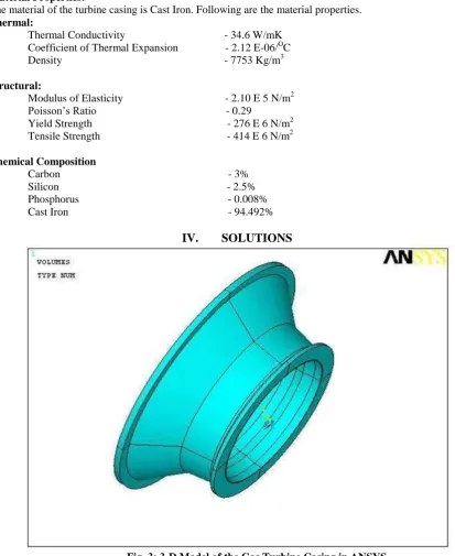
Fig. 3: 3-D Model of the Gas Turbine Casing in ANSYS
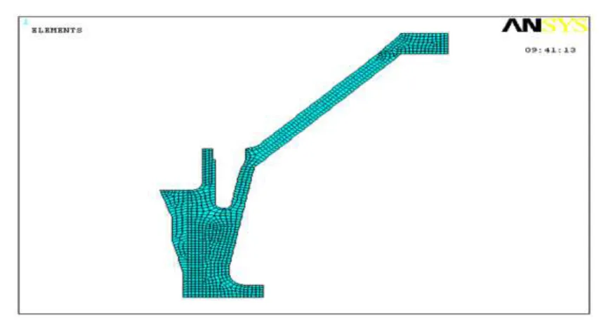
Fig. 4: Meshed View of the Gas Turbine Casing
Case 1: Temperature and Von Mises Stress Distribution of Actual Casing Design
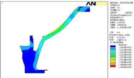
Fig. 5: Temperature Distribution Contours in ANSYS
Fig. 5 and fig. 6 represents the thermal analysis and structural analysis of the turbine casing. In this analysis, inside heat transfer coefficient and bulk temperatures are applied to the inner surface of the gas turbine casing, outside heat transfer coefficient and bulk temperatures of air side are applied to the outer side of the casing master model. Inside temperature of 963o C and outside temperature of 485o C are applied along the inner side of the casing. For structural analysis, inside and outside pressure of 10 bar and 1.013 bar are applied respectively to the casing. From fig. 6, the maximum stress obtained is 48.4 Mpa, with a factor of safety 5, the maximum stress is 242 Mpa. This value is found within the limit of yield stress value of 276 Mpa. Therefore, it is concluded that the existing design is safe.
Case 2: Temperature and Von Mises Stress Distribution at Increased Temperatures of 1100oC and 600oC
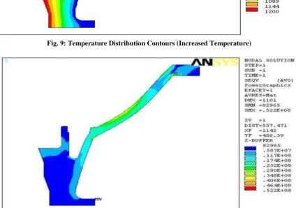
Fig. 7: Temperature Distribution Contours (Increased Temperature)
Fig. 7 and fig. 8 represents the thermal and structural analysis of the turbine casing with increased working gas temperature i.e. 1100o C at inside and 600o C at outside of the casing. The temperature distribution and stress distribution at these conditions are shown in the above figures. It is observed that the stress in the casing is increased with the increased gas temperature and pressure. Maximum stress developed is 50 Mpa. The stress value with a factor of safety reaches to 250 Mpa. It is observed that this value is also within the limit.
Case 3: Temperature and Von Mises Stress Distribution at Increased Temperatures of 1200oC and 700oC
Fig. 9: Temperature Distribution Contours (Increased Temperature)
Fig. 10: Von Mises Stress (Pressure) Contours at Increased Temperatures
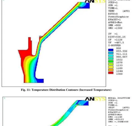
Case 4: Temperature and Von Mises Stress Distribution at Increased Temperatures of 1300oC and 800oC
Fig. 11: Temperature Distribution Contours (Increased Temperature)
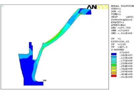
Fig. 12: Von Mises Stress (Pressure) Contours at Increased Temperatures
Case 5: Temperature and Von Mises Stress Distribution at Reduced Actual Casing Thickness of 5 mm
Fig. 13: Temperature Distribution Contours (Reduced Thickness of 5 mm)
Fig. 14: Von Mises Stress Contours at Reduced Casing Thickness of 5 mm
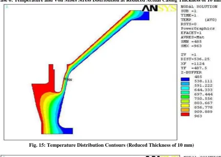
Case 6: Temperature and Von Mises Stress Distribution at Reduced Actual Casing Thickness of 10 mm
Fig. 15: Temperature Distribution Contours (Reduced Thickness of 10 mm)
Fig. 16: Von Mises Stress Contours at Reduced Casing Thickness of 10 mm
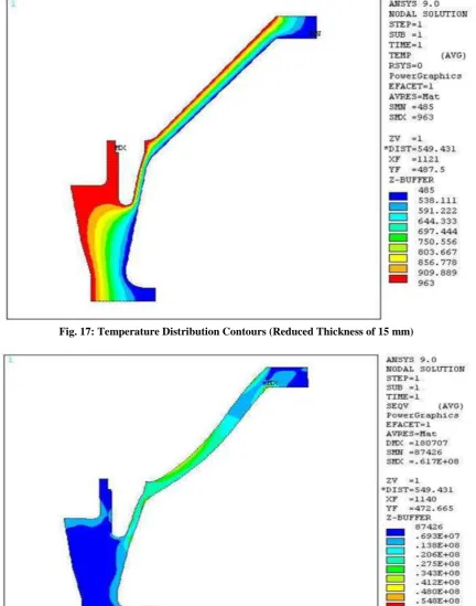
Case 7: Temperature and Von Mises Stress Distribution at Reduced Actual Casing Thickness of 15 mm
Fig. 17: Temperature Distribution Contours (Reduced Thickness of 15 mm)
Fig. 18: Von Mises Stress Contours at Reduced Casing Thickness of 15 mm
V.
RESULTS
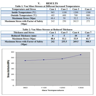
Table 1: Von Mises Stresses at Different Increased Temperatures
Temperature and Stress Case 1 Case 2 Case 3 Case 4
Inside Temperature (oC) 963 1100 1200 1300
Outside Temperature (oC) 485 600 700 800
Maximum Stress (Mpa) 48.4 50 52.2 54.4
Maximum Stress with Factor of Safety (Mpa)
242 250 262.5 272
Table 2: Von Mises Stresses at Reduced Thickness
Thickness and Stress Case 1 Case 5 Case 6 Case 7
Reduced Thickness (mm) 0 5 10 15
Maximum Stress (Mpa) 48.4 51.1 53.9 61.7
Maximum Stress with Factor of Safety (Mpa)
242 255.5 269.5 308.5
Fig. 19: Stress Distribution vs Gas Temperature
Fig. 19 represents the stress distribution of the gas turbine casing against various temperatures of working gas. From the figure, as the temperature of the working gas increases, the stress values in the casing material also increases.
Fig. 20 represents the stress distribution of the gas turbine casing against reduced thickness at the outside surface of the turbine casing in equal decrements. From the figure, as the outside thickness of the casing decreases, the stress values increases.
VI.
CONCLUSIONS
The structural and thermal analysis is carried out on the gas turbine casing using finite element method concept. The following conclusions are drawn from the present investigation.
The temperature has a significant effect on the overall stresses in the turbine casing and maximum stresses induced are within safe limit. As the temperature of the working gas increases in equal range, the stress values induced in the casing material also increases.
Corresponding to the inside and outside temperature of 963oC and 485oC, the stress developed in the turbine casing is 48.4 Mpa. With a factor of safety 5, the stress is 242 Mpa. Both these values are within the yield stress value of the casing material. Similarly, by increasing the working gas temperatures at inside and outside of the casing up to 1300oC and 800oC respectively, maximum stress value observed is 54.4 Mpa. With a factor of safety 5, the stress value is 272 Mpa. This value is nearly equal to yield stress value of the casing material. Hence, it is concluded that the temperatures of the working gas cannot be increased beyond this value.
Additionally, it is concluded that the outside thickness of the casing cannot be decreased beyond 15 mm of the actual design since the induced stresses in the modified design are more than the yield stress value of the casing material which leads to turbine failure. It is also concluded that as the outside thickness of the casing decreases, the stress values simultaneously increases.
REFERENCES
[1]. Thirupathi R. Chandrupatla & Ashok D.Belegundu, Finite Elements in Engineering, Prentice-Hall of India, New Delhi, 2001.
[2]. S. Moaveni, Finite Element Analysis: Theory and Application with ANSYS, Pearson Education, 2008.
[3]. C Rajesh Babu, “Thermal Stress Analysis of a Gas Turbine Casing Using FEA”, International Organisation of Scientific Research, Journal of Mechanical and Civil Engineering, vol. 11, Issue 4, pp. 32-37, Aug. 2014.
[4]. Manual of Gas Turbine General Design Data, Installation and Performance Rating, General Electric Gas Turbine Division.
[5]. ANSYS 5.4 User Manual, ANSYS Inc., 2006.
[6]. Guntukula Srikanth, Dinesh Bajaj and K.S. Naidu, “Structural and Thermal Finite Element Analysis of Gas Turbine Rotor Blade”, International Journal & Magazine of Engineering, Technology, Management and Research, vol. 2, Issue 10, pp. 457-463, Oct. 2015.
[7]. S.Gowreesh, “Convective Heat Transfer Analysis Of An Aero Gas Turbine Blade Using Ansys”, International Journal Mechanics Of Solids, vol. 4, 2009.
[8]. John. V, T.Ramakrishna. “The Design and Analysis of Gas Turbine Blade”, International Journal of Advanced Research and Studies, vol 2, Issue 1, Dec. 2012.