Page 137 www.ijiras.com | Email: [email protected]
Basic Comparison Of Fix Capacitor-Thyristor Controlled Reactor,
FC-TCR (SVC) And Thyristor Controlled Series Capacitor (TCSC)
In Electric Power System
Nwozor Obinna Eugene
Department of Electrical and Computer Engineering, Federal University of Technology, Minna, Niger State,
Nigeria
Olumoko Olayinka Eric
Hydraulic Equipments Development Institute, Kumbotso, Kanu, Nigeria
I. INTRODUCTION
FACTS equipments by IEEE recommendation are categorized into series, shunt and combined series-shunt controllers. Among the series elements of the FACTS family include thyristor controlled series capacitor (TCSC), static synchronous series compensator (SSC) etc.
The series reactance of power lines can be improved upon to meet the system requirement in attempt to enhance the active power flow on the line .In this case; the existing branch voltages are coupled in series with the line so as to achieve optimum power transfer. Similarly, improvement of bus voltages is often by automatic amendment of susceptance of installed shunt component on the bus.
In some cases, direct effect of the improved voltage magnitudes on the network buses stems from the impact of bus connected FACTS components such as shunt controllers – SVC, STATCOM etc and this influence is not monopolized by
the connecting bus areas only; but can be far reaching to other neighboring buses, depending on the reactive power compensation capability of the shunt controllers in question. This augments system voltages in order to eliminate bus voltage deficit.
In a true network operation where the system’s high operational efficiency is in great demand, it is seldom having a situation where only a single controller functions to achieve all the network requirements. As a result; agglomeration of the functional input of the three categories is always experienced in order to benefit from the independent properties of each of the FACTS controller family.
Also, Integration of the series and shunt FACTS controllers into a single component for efficient operation of power system can be appropriated from the combination of the two devices out of the two independent categories to form composite equipment known as shunt-series controller. In effect, separate inherent functional characteristics of each of
Abstract: In this work, effort is concentrated on explicit exposure of similarities and differences between FC-TCR and TCSC devices in electric system. Several distinct and common operational features of the two components are addressed and evaluated to build a comprehensive analysis for adequate comparison and contrast of the FACTS controllers. The two different models of the devices that split up their identically composed adjustable parameters (in terms of constituting components) into and are clearly demonstrated in attempt to ex-ray the relative functionalities of the controllers in power system. All the diagrams are very illustrative in picturing out the structural composition of FC-TCR and TCSC equipments in order to point at the obvious similitude of their basic circuit. Apart from the self-explanatory and theoretical preamble that leads the introduction, the nature of the work takes a posture of two-way stance in which the similar and varied characteristics of the controllers are vertically featured; thereby, covering the structural, functional and “installational” comparison; all displayed in a tabular form.
Page 138 www.ijiras.com | Email: [email protected] the constituent members is being harnessed to achieve a better
performance that may not be completely offered by one alone, when operating independently from the other in the system. As a result, unified power flow controller (UPFC) can control a host number of system situations in accordance to the behavior of individual constituents of the unit. This is more preferable considering cost implication; especially, when embarking on a large scale system improvement planning.
In sumary, there is always integration of the functional potency of the three classes in the light of accomplished optimum equipment localization within the network; and this to a larger extent helps to induce a high degree of steady and dynamic stability of the power system; thus, establishing a rugged and efficient electrical environment through the system operation under a well electrically instituted conditions such as
Proper sub-synchronous resonance (SSR) control A constant electrical fault-free condition
Effective power flow control as well as
Adequate power oscillation damping within the power system.
FACTS equipment has been defined by IEEE as “AC” transmission system incorporating power electronic based and other static controllers to enhance controllability and increase power transfer. Inclusion of power electronics as the basic components of the equipments suggests the key functional entity of the devices and this is glaring from the control concept of the system. As such, thynistor devices have immensely contributed to the success in usage of FACT controllers, since, the adjustment of the network constants to implement the desired system objectives is necessitated by the power electronic composition. Through a firing and appropriately timed pulses, the right firing angle, α , can be decided for triggering on and off , the thyristor switches. This is done on a considerable level of precautions to avoid operating within the resonance angle, and the tendency for system oscillation.
SECTION 1
MODELING OF STATIC VAR COMPENSATOR (SVC) AND THYRISTOR CONTROLLED SERIES CAPACITOR.
THYRISTOR CONTROLLED SERIES CAPACITOR MODEL
The equivalent reactance of the system that is connected with TCSC is the summation of adjustable TCSC reactance,
and the natural reactance of the system lines, itself. Among the components of line reactance are the line charging capacitance and inductance, neglecting the line resistance. Therefore; for a system with installed TCSC component, the equivalent line reactance of the network is as stated below
Figure 1.0: Diagram showing line series circuit of an TCSC device
=
=
=
Taking, = and
By substitution, =
= ………..(2)
Where,
Xequ. = Equivalent or total reactance on the system. = natural line reactance of the system
IL (α)(s) = I0 B [Sin t - Sin t]… …..(3)
From the basic circuit of figure 1 above, the thyristors of the circuit decide the level of participation of capacitor component for line compensation. The capacitor can be completely bypassed when the thyristor switches are fired at a suitable angle, ; then, allowing line current to pass through inductor branch and resulting such expressions as
IL (α)(s) = I0 B [Sin t - Sin t]……… …..(3)
(for inductor current)
Full capacitive compensation occurs when SW1 and SW2 thyristor are switched off as shown, permitting the current flow through capacitor C only. See the diagram below
Figure1.1: Diagram showing the line series TCSC circuit with thyristor component switched off
Therefore; the quantity of current that are allowed to pass through the capacitor determines the extent of charging and discharging of C and the development of voltage magnitude which Is in quadrature with the line current and in series with the line. The voltage expression is as shown below
VC (t) = I0 [Cos𝝎t] ………(4)
This largely account for the system reactive power compensation as obtained with thyristor controlled series capacitor (TCSC).
Page 139 www.ijiras.com | Email: [email protected]
Figure 1.2: Diagram showing the graphical illustration of the dependency of thyristor firing angle on the TCSC equivalent
susceptance
The positive half with the curve extending from
( ), sweeping across the plane towards the resonance shows the inductive region. The firing angles that are traceable to this curve are the range of angles within which inductive compensation is attainable, with being the maximum attainable equivalent reactance.
The effectiveness of the equivalent reactance, for TCSC is limited at the resonance point where = ; and for normal operations, the firing angle must be maintained at a particular length, away from the resonance angles This gives room for maximum and minimum reactance (i.e and ) corresponding to the upper and lower bound of axis respectively. From the graph, at = 0, there is a continuous triggering of the thyristor switches. Thus, the basic circult behaves as a parallel connected L C circuit. This is known as bypass mode. When 00< < , the angle ranges below the resonance angle, but greater than 00; and at this range, the equivalent reactance, is positive and inductive. This is refereed as inductive boost mode.
In capacitive boost mode, angle is greater than resonance angle, but lesser than 900 (i.e. < 0). As such the equivalent reactance is negative and capacitive in nature. Subsequently, as the firing angle equals 900, ( 900) the thyristor is no more conductive and triggerable. As result, the effect of the fixed capacitor is largely felt on the line and this is called blocking mode.
For static Var Compensator, the adjustment of line parameters is by maneuvering the inductive susceptance of the device, which is controllable through the thyristor firing angle to determine the branch current. It is worth knowing that capacitor C is fixed in value and can allow capacitive current into the line depending on SW1 and SW2 switching mode. The expression that relates the inductive and capacitive reactance in the circuit can be derived thus:
II. STATIC VAR COMPENSATOR MODELING In this modeling, a FC-TCR basic circuit which is the same in component composition with the TCSC counterpart is presented; though with absolute incongruity in terms of direction and area of installation in power system, as we can
observe comparing the two modeling. As shown below, unlike TCSC equipment; the device occupies the bus through a protective circuit breaker and a shunt transformer to emerge a typical variable susceptance, assumed as the element of reactive power control for bus voltage improvement. The equivalent susceptance of the device, comprises of thyristor-dependent adjustable inductive susceptance,
and a fixed capacitive, susceptance, ;all mathematically related with the natural constituent variables as shown in the equations.
Figure 1.3: Diagrm showing the circuit and inductive susceptance of an FC-TCR device
= + ……….. (5)
=
= -Therefore,
=
=
Where:
= Capacitive reactive current, = Inductive reactive current
= SVC net reactive current, = SVC variable susceptance
= inductance of the SVC device, = Fixed capacitor of the device
= equivalent Susceptance, = inductive susceptance
= Capacitive susceptance, SW1 & SW2 = thyristor switches
Just as it is obtained in TCSC model, the SVC variable susceptance can also be adjusted for voltage control via the thyristor firring angles which by definition is a delay angle measured from the peak of capacitor voltage to the firing instant. As the reactive power compensation is adversely limited at the resonance angle in TCSC; for SVC, the resonance effect is not a problem; being that the basic modules are shunt connected, it therefore means that the module is discounted; in effect, the unavailable band around zero as can be seen from the graph of equivalent susceptance below is not regarded
C
LSW1
SW2
IL( ) I
C
B
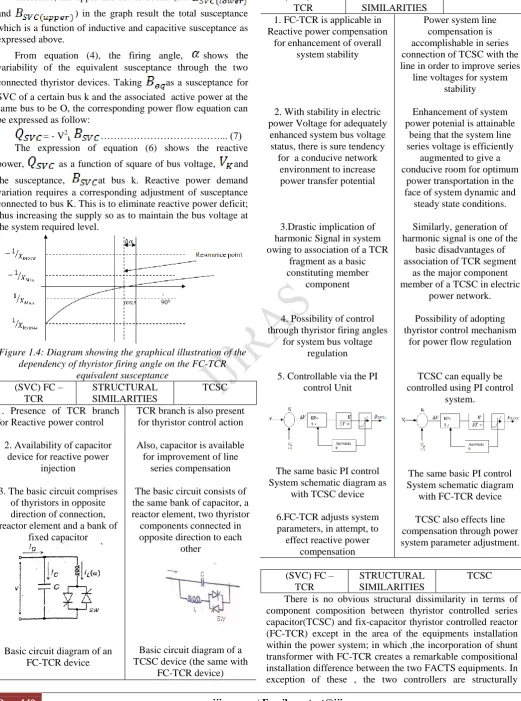
SVCPage 140 www.ijiras.com | Email: [email protected] Therefore, the upper and lower bound (i.e.
and ) in the graph result the total susceptance which is a function of inductive and capacitive susceptance as expressed above.
From equation (4), the firing angle, shows the variability of the equivalent susceptance through the two connected thyristor devices. Taking as a susceptance for SVC of a certain bus k and the associated active power at the same bus to be O, the corresponding power flow equation can be expressed as follow:
= - V2k ………... (7)
The expression of equation (6) shows the reactive power, as a function of square of bus voltage, and the susceptance, at bus k. Reactive power demand variation requires a corresponding adjustment of susceptance connected to bus K. This is to eliminate reactive power deficit; thus increasing the supply so as to maintain the bus voltage at the system required level.
Figure 1.4: Diagram showing the graphical illustration of the dependency of thyristor firing angle on the FC-TCR
equivalent susceptance
(SVC) FC – TCR
STRUCTURAL SIMILARITIES
TCSC 1. Presence of TCR branch
for Reactive power control 2. Availability of capacitor
device for reactive power injection
3. The basic circuit comprises of thyristors in opposite direction of connection, reactor element and a bank of
fixed capacitor
Basic circuit diagram of an FC-TCR device
TCR branch is also present for thyristor control action Also, capacitor is available for improvement of line
series compensation The basic circuit consists of the same bank of capacitor, a reactor element, two thyristor components connected in opposite direction to each
other
Basic circuit diagram of a TCSC device (the same with
FC-TCR device)
(SVC) FC – TCR
STRUCTURAL SIMILARITIES
TCSC 1. FC-TCR is applicable in
Reactive power compensation for enhancement of overall
system stability
2. With stability in electric power Voltage for adequately
enhanced system bus voltage status, there is sure tendency
for a conducive network environment to increase power transfer potential
3.Drastic implication of harmonic Signal in system owing to association of a TCR
fragment as a basic constituting member
component
4. Possibility of control through thyristor firing angles
for system bus voltage regulation 5. Controllable via the PI
control Unit
The same basic PI control System schematic diagram as
with TCSC device
6.FC-TCR adjusts system parameters, in attempt, to
effect reactive power compensation
Power system line compensation is accomplishable in series connection of TCSC with the line in order to improve series
line voltages for system stability Enhancement of system power potenial is attainable
being that the system line series voltage is efficiently
augmented to give a conducive room for optimum
power transportation in the face of system dynamic and
steady state conditions. Similarly, generation of harmonic signal is one of the
basic disadvantages of association of TCR segment
as the major component member of a TCSC in electric
power network. Possibility of adopting thyristor control mechanism
for power flow regulation
TCSC can equally be controlled using PI control
system.
The same basic PI control System schematic diagram with FC-TCR device TCSC also effects line compensation through power
system parameter adjustment.
(SVC) FC – TCR
STRUCTURAL SIMILARITIES
Page 141 www.ijiras.com | Email: [email protected] equivalent, apart from in minor situations where inclusion of
some accessorial equipments are done on the basis of achievement of a desired purpose such as in harmonic control. Etc
(SVC) FC – TCR
STRUCTURAL SIMILARITIES
TCSC 1.Fundamentally, the chief
functional behavior of FC-TCR devices in electric system is to upgrade the system bus voltages
so as to enhance stability.
2.For FC-TCR and other devices in SVC family, resonance angle, does not
cause problem when the thyristor angles are manipulated
for susceptance adjustment
3.The range of firing angle variation mathematically exists
within
for adequate compensation function
4.Variable reactance equation is inverse of that of TCSC:
5.The PI control output for
FC-TCR Is
6.FC-TCR is installed in shunt with the system bus
The apparent and distinguishing operational
activities of a TCSC in electric system is in improvement of electric power flow through line series voltage supplement.
Variation of thyristor control angles into the resonance, results power oscillatory problem.
For that a short angular distant, is usually maintained within the inductive plane to avoid power system oscillation
while varing the angle. The range of thyristor
firing angle variation is mathematically
obtained within for effective compensation.
The variable reactance equation is the the inverse
of that of FC-TCR:
=
The PI control output for TCSC is The TCSC is installed in
series with transmission lines.
III. CONCLUSION
It is important to note that the two devices share the same structure just as briefly explained in the comparison table since the component composition of the two equipments are common. In the case of functional behavior and characteristics in terms of steady state condition evaluation; the two are obviously related considering the reactance of the TCR fragment which is the major points of similarity of the two; visa-vise, the operational effect on the system.
With FC-TCR and other family members of static Var compensators, SVC; if the device is at the system bus voltage location and the operating voltage on the FACT elements is the bus voltage and a sinusoid; a furrier analytical evaluation with respect to reactor current waveform gives a clear view of TCR reactance at fundamental frequency to be similar with adjustable reactance expressed as
= ………..(8)
= ………(9)
Thus, the equation can be further expanded to incorporate the capacitive and inductive reactance ratio in the overall effective reactance as shown below:
= ….(10)
=
……(11) Where,
= , the inductive reactance of the reactor at fundamental frequency. = , the capacitive reactance of the capacitor at fundamental frequency.
α = thyristor firing angle
= system fundamental frequency = inductance of the reactor of the device C = the device capacitor
The extent of the equipment functional participation is the decision of the thyristor firing angle whose range of variation is predetermined at the manufacturing stage. Adjustment of the controller through the angle enables the effective reactance variation so as to determine the degree of bus voltage changes assuming the basic circuit is connected in shunt with the bus.
Functionally FC-TCR is always installed on the bus through a step down transformer; (unlike TCSC device that occupies the line in series order) on the high voltage or extra-high voltage side as the case may demand so as to reduce the device voltage to such a bearable capacity as 50kv and below
Page 142 www.ijiras.com | Email: [email protected] line for distinction between the two devices . In the mode as
seen above, the equivalent circuit can conveniently serve a major purpose of real power flow enhancement in assumption of series position with the line .Thus; voltage incorporated from the circuit, complements the natural series line voltage of the system to reinforce the network power transfer potential. On the other hand; the TCSC adjustable series reactance
( ) automatically changes to FC-TCR
adjustable susceptance ( = or ) when connected in shunt to bus for exchange of reactive power with the system in other to regulate bus voltages.
REFERENCES
[1] A.L. Ara, S.A Nabavi Niayki. (2003) Comparison of the fact equipment operation I transmission and distribution system. E-mail: [email protected]
[2] N.G Hingorani, L.Gyugyi. (2000). understanding FACTS concept and technology of flexible AC transmission system
[3] Gribel, J., et al., “Brazilian North-South Interconnection – Application of Thyristor-Controlled Series Compensation (TCSC) to Damp Inter Area Oscillation Mode,” CIGRE Paper No. 14-101, 1998.