Analysis of Power Flow Control in Power System using Thyristor
controlled series capacitor Device (TCSC): A Review
Gautam Shah & Durgesh Vishwakarma
M.tech Scholar
1, Asst Professor EX Department, REC Bhopal
Abstract— The world's electric power supply systems are widely interconnected. We need these interconnections because, apart from delivery, the purpose of the transmission network is to pool power plants and load centre in order to minimize the total power generation capacity and fuel cost. Today’s power system demand have been increase with loads, it is more difficult to provide stability and control. In this paper analysis of power flow control in power system using Thyristor controlled series compensation and performance of TCSC is given. FACTS technology new opportunities for controlling power and enhancing the usable capacity of present, as well as new and upgraded lines. In this paper the study of TCSC with capacitive
Fig. 1: Symmetrical two area lossless transmission line
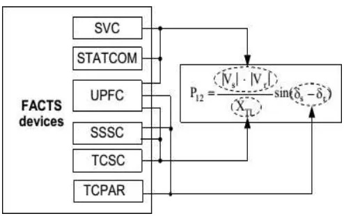
The power flow P in the transmission line as. | V | . | V |
and Inductive mode of operation and applications, advantages of FACTS. Thyristor controlled series compensation consist of series capacitor shunted by back to back thyristor. By changing the firing angle of this back to back thyristor possible to vary the
P
s r sin( XTL
s
r )reactance of the TCSC as per TCSC characteristics. This compensation controls the transmission line reactance to improve the real power flow. TCSC in capacitive region power flow increasing and in capacitive region power flow decreases.
Keywords— Flexible AC Transmission System (FACTS), Power Flow analysis, TCSC.
I.INTRODUCTION
Electricity is an everyday as it was an essential part of our life and need to get electricity to the consumer in reliable and specified quality. Transmission of electricity in the interconnected cooperating electricity system is steadily increasing due to increasing growth in consumption and electricity generation. World-wide transmission systems are undergoing continuous changes and restructuring. They are becoming more heavily loaded. The transmission systems must be flexible to react to more diversified generation and load patterns. The three control parameters such as voltage magnitudes, phase angle and line reactance Governs flow of power in the transmission system. Considering a symmetrical lossless transmission line of Fig. 1 between two areas, the power flow P in the transmission line can be expressed as:
Whereas |Vs| & |Vr| are the sending end and receiving end voltage magnitudes and (δs – δr) are phase angle between the two ends. Considering resistance and susceptance as negligible, XTL is defined as reactance of the transmission line
(FACTS) & CONTROLLERTYLE AND FONTS
Flexible AC Transmission system technology opens up new opportunities for controlling power and enhancing the usable capacity of present, as well as new and upgraded lines. The FACTS devices are certainly an improvement over the conventional methods as they are fast and control these parameters efficiently to manage power flow effectively in transmission system. These opportunities arise through the ability of FACTS Controllers to control the interrelated parameters that govern the operation of transmission systems including series impedance, shunt impedance, current, voltage, phase angle, and the damping of oscillations at various frequencies below the rated frequency. In general, FACTs controller may divided into four categories as shown in figure. 2
Fig.2. Classification of FACTS controllers.
Fig. 3:Representation of different type’s controllers controlled different parameters of transmission line.
The basic applications and advantages of FACTS devices are:
1.Power flow control 2.Voltage control 3.Reduce system losses 4.Reactive power compensation 5.Enhance power system stability 6.Power quality improvement.
7.Flicker mitigation Power conditioning 8.Increased system security and reliability
9.Rapid, continuous control of the transmission line reactance
10.Optimizing load sharing between parallel circuits
III. TCSC AND POWER FLOW CONTROL
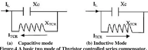
In this mode TCSC is used dynamically, It Consist of three components as capacitor banks C, bypass inductor L and bidirectional thyristors T1 and T2. The firing angles of the thyristors are controlled to adjust the TCSC reactance in a system control algorithm, normally in response to some system parameter variations. However, a practical TCSC module also includes protective equipment normally installed with series capacitors, as shown in Figure 3
(a) Capacitive mode (b) Inductive Mode
Figure.4 A basic two mode of Thyristor controlled series compensator.
TCSC is a series FACT device available for application in AC line of voltage up to 500 KV. In Figure.3 Shown equivalent circuit of the TCSC model as a capacitance in parallel with a variable inductor.
The impedance of TCSC (ZTCSC)
ZTCSC = (-jXc) (jXTCR) / j(XTCR-XC)
ZTCSC= (-JXc) / (1-Xc/ XTCR)
The current through the TCR (ITCSC) is given by ITCSC = (-jXc) IL / j(XTCR - Xc )
ITCSC = IL / (1 – XTCR / Xc )
Since the losses are neglected, the impedance of TCSC is purely reactive. The capacitive reactance of TCSC is obtained
from figure 9.
XTCSC = Xc / (1 – Xc / XTCR)
IV.MODES OF TCSC
There are essentially three modes of TCSC operation. These are illustrated in Figure below
1. Bypassed Thyristor Mode: - In this bypassed mode, the thyristors are made to fully conduct with a conduction angle of 1800. The susceptance of the reactor is greater
than capacitor. Gate pulses are applied as soon as the voltage across the thyristors reaches zero and becomes positive, resulting in a continuous sinusoidal of flow current through the reactor and thyristor valves. The TCSC module behaves like a parallel combination of capacitor and inductor. This mode is employed for protection of capacitor against overvoltage.
2. Blocked Thyristor Mode: - This mode also known as the
waiting mode. In this mode no current pass through the thyristor valves and firing pulses to the thyristor valves is blocked. If the thyristors are conducting and a blocking command is given, the thyristors turn off as soon as the current through them reaches a zero crossing. The TCSC module is thus reduced to a fixed series capacitor, and the net TCSC reactance is capacitive. The reactance of TCSC and Fixed capacitor is similar.
3. Partially Conducting Thyristor or Vernier Mode: - In
this mode thyristor valves are operated by two gate pulses in the two region i.e capacitive region and inductive region. This mode allows the TCSC to behave either as a continuously controllable capacitive reactance or as a continuously controllable inductive reactance. It is achieved by varying the thyristor pair firing angle in an appropriate range. However, a smooth transition from the capacitive to inductive mode is not permitted because of the resonant region between the two modes. The loop current increases the voltage across the FC, is constrained in the range αmin ≤ α ≤ 1800. This constraint
provides a continuous vernier control of the TCSC module reactance. The loop current increases as α is decreased from 1800 to α
min. Another variant is the
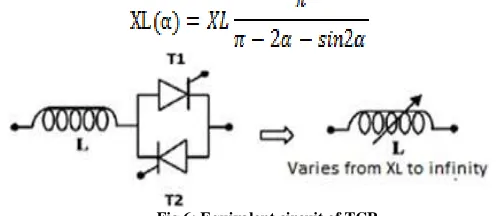
The basic operation of TCSC can be easily explained from circuit analysis. It consists of a series compensating capacitor shunted by a Thyristor controlled reactor (TCR). TCR is a variable inductive reactor XL shown in figure. Controlled by firing angle α. Here variation of XL with Respect to is α given by
Fig.6: Equivalent circuit of TCR
For the range of 0 to 900 of α, XL(α) start vary from actual
reactance XL to infinity. This controlled reactor is connected across the series capacitor, so that the variable capacitive reactance shown in figure 18 is possible across the TCSC to modify the transmission line impedance. Effective TCSC reactance XTCSC with respect to firing angle alpha (α) is
Where
Fig.7: Equivalent circuit of TCSC
2.αLlim < α < αClim Capacitive region. 3.αClim < α < 1800 Resonance region.
While the maximum and minimum value of firing angles should be selected in such a way as to avoid the TCSC operating in high impedance region (at resonance) which results in high voltage drop across the TCSC.
Fig.8: Impedance versus firing angle Characteristics of a TCSC
VI. CONCLUSION
In this paper, the used of TCSC in power flow control between two ends of the transmission line to maintain the voltage magnitude, phase angle and line impedance. The study of Series compensation TCSC device to controlling the power flow through the transmission line by changing the effective reactance of the system. The TCSC can be operated in generally two modes as inductive and capacitive mode. The various FACTS controller with its classification. The advantages of FACTS devices in power system and various operating modes of TCSC are specified. This paper work can be extended in future for TCSC modelling and simulation with a number of bus system for controlling the power flow.
REFERENCES
[1]
N.G. Hingorani, L. Gyugyi, 1999, ―Understanding FACTS: Concepts and Technology of Flexible AC Transmission Systems,‖ IEEE Press, New York.[2]R. M. Mathur, R. K. Varma, ―Thyristor-Based FACTS Controllers for Electrical Transmission Systems‖, Piscataway, NJ: IEEE Press, 2002
[3]Prabha Kundur, ―Power system stability and control‖ The Mc Graw Hill companies, Inc., New York, 1994 [4]T. J. Miller, ―Reactive power Control in Electric
Systems,‖ John Willey & Sons, 1982
[5]S. Meikandasivam, Rajesh Kumar Nema and Shailendra Kumar Jain,―Behavioral study of TCSC device A MATLAB/Simulink mplementation‖, International Journal of Electronics and Electrical Engineering, vol. 2, no. 10, Oct. 2011, pp. 151– 161
[9]Vatsal J. Patel, C.B.Bhatt ―Simulation and Analysis Real and Reactive Power Control with Series Type FACTS Controller‖ IJETAE, Volume 2, Issue 3, March 2012, pp.7-11
[10] Narayana Prasad Padhyay and M.A. Abdel Moamen‖ ―Power flow control and solutions with multiple and Multi Type FACTS devices‖,
Electric Power Systems Research, Vol.74, 2005, pp. 341-351 [11] Priyanka Kathal, Arti Bhandakkar ―Power
Flow Control in Power System using Thyristor controlled series capacitor IJSR INDIA ISSN: 2319- 7064, pp.72-83 [12] Anita Kanwar, Rachit Saxena “Behavior of
TCSC in transmission line using MATLAB/Simulation‖ ISSN (Online) 2321 – 2004 ISSN (Print) 2321 – 5526, pp.195-197