Design of a CPW-fed Compact Dual Band (UWB/Bluetooth)
Integrated Antenna with Single Band Notched Features
1
Sarita Singh,
2Piush Kumar Singh
1,2Dept. of Electronic & Communication Engineering B.I.T, Meerut, India
Abstract
A concise, low-profile, and planar ultra-wideband and (UWB) Bluetooth integrated antenna with dual Band WiMAX/WLAN (3.4/5.5) rejected features is proposed. The antenna works dual-band operation covering 2.4–2.484 GHz (Bluetooth) and 3.1– 10.6 GHz (UWB) frequency band with single Band WLAN (5 to 6 GHz) rejected features. It is fed by the CPW and built on a substrate FR-4. By cutting C-shaped slot in the patch band-rejected filtering property for WLAN band is achieved.The calculated and simulated results are agreed fine. The antenna shows acceptable gain uniformity with stable omnidirectional radiation patterns across the UWB and Bluetooth integrated bands. The average group delay is around of 0.2 ns across the UWB frequencies.
Keywords
Bluetooth, Coplanar Waveguide (CPW) Fed Antennas, Integrated Antenna, Ultrawideband (UWB)
I. Introduction
Since the wireless system based on the ultrawideband (UWB) radio technology, for the short distance communication ranges (4–10 m), produces low output power and high data rate over frequency range of 3.1–10.6 GHz. An application that provides tracking capabilities over increased link range of over 30 m is supported. A wireless universal serial bus (USB) enabler has an application where communication between a PC and peripherals is needed UWB applications in mobile handsets are also expected. Over the nominated bandwidth of UWB system, there are some other narrowband services also exist, which are already occupied frequencies in the UWB frequency range, such as wireless local-area network (WLAN) IEEE802.11a and HIPERLAN/2 WLAN operating in the 5–6 GHz band. In some applications, UWB antenna uses filters to suppress dispensable bands. However, the uses of filters indeed increase the complexity of the UWB system and lead to increase in cost. It is desirable to design the UWB antenna with single notched frequency band in 5–6 GHz to minimize the potential interferences between UWB system and narrowband systems. So far, several design methods and structures have been reported. These UWB antennas with filtering property at the 5–6 GHz band have been proposed not only to mitigate the potential interferences but also to remove the requirement of an extra bandstop filter in the system [2-3].
Recently, more and more band-notched UWB antenna designs have been proposed. J.Kim et al. proposed a 5.2 GHz notched UWB antenna using slot-type SRR [6]. This UWB antenna fulfils all the critical requirements including high radiation efficiency, low-profile, stable radiation patterns and constant gain. However, the input impedance is not well matched at the lowest frequencies (3.1–3.8 GHz). In addition, the notched frequency band from 5–5.3 GH cannot successfully block out the whole WLAN bands. The potential interferences between the UWB and WLAN systems cannot be reduced to the minimum. Yi-Cheng Lin et al. discussed the designs of three advanced band-notched (5–6 GHz) UWB rectangular aperture antennas [3]. The antenna structure is simple and the aperture size is compact. Broad impedance bandwidth
and stable radiation patterns are obtained, whereas the ground plane dimension is a bit of large. In practice, when integrated with the system board of different ground plane size, the antenna might need a retuning for the optimized dimensions. Wang-Sang Lee et al. proposed wideband planar monopole antennas with dual band-notched characteristics [4]. This technique is suitable for creating UWB antenna with narrow frequency notches or for creating multiband antennas. However, the antenna is not suitable for integration with compact systems, because its ground plane is very large and it is perpendicular to the radiator, which limits its applications in compact UWB systems. Furthermore, the bandwidth performance of the antenna is from 2 GHz to 6 GHz, which can not satisfy the demands of UWB system. Based on the above researches in 2008, Qing-Xin Chu proposed a simple and compact CPW-fed planar UWB antenna [5] with dual band-notched characteristics in 3.4 GHz (3.3–3.8 GHz) and 5.5 GHz (5–6 GHz). The dual band-notched operations are achieved by etching two nested C-shaped slots in the rectangular metal radiating patch but it was not integrated ultrawideband and (UWB) Bluetooth also Bahadir S. Yildirim design a Integrated Bluetooth and UWB Antenna [6] but it is not compatible to suppress the interference with others services like WiMAX and WLAN.
Fig. 1: Simulated VSWR of Fig. 2 (a) With Slot and Without Slot in Radiating Patch With Optimal Dimensions
(a)
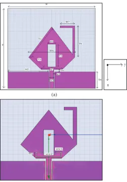
Fig. 2: Antenna (a) and (b) With Optimized Dimensions (a) Without Notch (b) With Single Notch and.
II. Antenna Designs and Result Discussion
In the design of fig. 2 (a) and (b), the length ‘T’ and width ‘W’ play an important role to determining the resonant frequency of the system. The initial values of these parameters are taken approximately one wavelength of center frequency (6.85 GHz) for the substrate height (h=1mm), dielectric constant (εr=4.4) and loss tangent d=0.02. The design of the UWB rhomboid antenna starts with choosing T1, T2, and W1. T1 and T2 are critical parameters associated with the upper and lower operating frequencies of the antenna. W1, on the other hand, is a key parameter to maintain good input impedance for the frequency range of 2.4–11 GHz. Accordingly, T1 and T2 are selected to have a reasonable VSWR at fmin = 3.1 GHz and fmax = 11.6 GHz, which are the lower and upper ends of the UWB band. A fine starting point for these dimensions is as follows:
T2 ≈ λe,fmax/4 (1)
T1+T2≈ λe,fmin/4 (2)
Where λe=λ0/√ɛe is the effective wavelength for the radiation mode in the FR-4 substrate with the effective dielectric constant (ɛe=1.02≈1 for the 1-mm FR-4 substrate). λe, fmax and λe, fmin are the effective wavelengths at the upper and lower UWB frequencies, respectively. W1 is chosen to obtain reasonable return loss values for the whole frequency band. In particular, the optimization of W1 is critical for obtaining a good match at the high end of the UWB spectrum. The L-shaped Bluetooth antenna element is strategically attached to the UWB antenna at one side at a position of minimum
UWB current point to ensure a minimal coupling between the two elements. This strip generates the 2.4–2.484 GHz Bluetooth band. The (TB=T6+W7) length of this strip is about a quarter-wave long
at the operating frequency fB=2.4 GHz
Tb = λe,B/4 (3)
The calculated values of the antenna are optimized with HFSS tool. The optimization has been done to perform for the most excellent impedance bandwidth. For design presented in the paper, the effective length of the c-shaped slot in the rhombic patch is approximately 0.5 times of wavelength of frequency 3.5 GHz which is lying in the undesirable band; and for 5-6 GHz band notch two symmetrically rectangular slots have been cut in ground plane with length 0.25 times of wavelength of 5.5 GHz. The final parameters of fig.2 (a) are T=41mm, T1=17.5mm, T2=7mm, T3=13mm, T4=9.6mm, T5=2mm, T6=18mm, W=40mm, W1=10mm, W2=19.65mm, W3=2mm, W4=4mm, W5=0.7mm, W6=22mm, W7=7mm; slot dimensions of the single notch in fig 2(b) are ww1=1.75mm, tt1=2.5mm, ww2=10 and slot dimensions of 5.5 GHz. The other dimensions which are not shown in Fig 2.(b) are same as in Fig 2. (a).
Fig. 3: Simulated VSWR of Fig. 2 (a) and (b) with optimal dimensions.
Fig. 2 shows the configuration of the proposed monopole antenna it consists a diamond shape radiating patch with rectangular slot and CPW fed with rectangular ground plane. The radiating patch slot provides an additional current path. So this structure changes the inductance and capacitance of input impedance which plays the important role to increase the impedance bandwidth, Fig. 1 shows the simulated VSWR without slot and with slot in radiating patch. The slot in radiating patch has a strong significant effect on the antenna’s bandwidth enhancement which is depicted by fig. 1. To reduce the interferences from the WLAN system, the band-notched function is popular in the UWB system. Fig. 1(b) shows the geometry and dimensions of the UWB antenna with filtering property operating in the 5-6 GHz bands.
By cutting a C-shaped slot in the rhombic radiating patch of Fig. 2(a), the frequency band notch is created. Note that when the band-notched design applied to (a), there is no retuning labour required for the earlier dimensions.
The notch frequency given the dimensions of the band notched characteristic can be given as
fnotch= C/2L√εe (4)
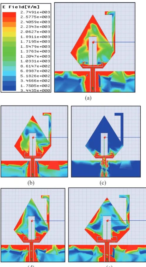
shows the comparison of VSWR of antenna (a), (b), and (c), the current distribution on the antenna has been also studied. Fig. 4(a)–(e) show the E-field distribution at 2.45, 4, 5.5, 8 and 10 GHz, respectively. As seen in Fig. 4(a), the resonant character of the Bluetooth element appears highlighted at 2.45 GHz. At 5.5 GHz as shown in Fig. 4(c), the E-field distribution flows around the C-shaped slot in rhombic. In this case, destructive interference for the excited surface currents in the antenna will occur, which causes the antenna to be nonresponsive at this frequency. The impedance nearby the feed-point changes acutely making large reflection at the desired notched frequencies. In addition, it is worthwhile mentioning that, according to the simulated current distributions, the current concentrates around the middle and bottom parts of the radiating patch. Therefore, the top of the radiating patch has minor effects on the antenna performance and might be removed for design purpose. In practice, when integrated with the system board, the antenna might need a retuning for the optimized dimensions The UWB element appears more active and the Bluetooth element appears colder at 4 GHz, as shown in Fig. 4(c). Finally at 10 GHz, the lower part of the UWB element appears active with a clear null at the Bluetooth element connection.
(a)
(b) (c)
(d) (e)
Fig. 4: Simulated Current Distributions at Different Frequencies. (a) 2.45 GHz, (b) 4 GHz, (c) 5.5GHz, (d) 8GHz and (e) 10GHz
Performance of the simulated VSWR of antenna with C-shape and rectangular shape slots is shown in Fig. 4. From the figure, it is clear that the wanted filtering property is introduced by the C-shape slot as expected. Fig. 5(a), (b) and (c), shows the VSWR of antenna shown in Fig. (b) With the variation of T1, T2 and T5.
(a)
(b)
(c)
Fig. 5: Simulated VSWR of Fig. 2 (c) with the variation of T1, T2, and T5 respectively.
Fig. 6: Simulated Group Delay of Antenna (a) and (b)
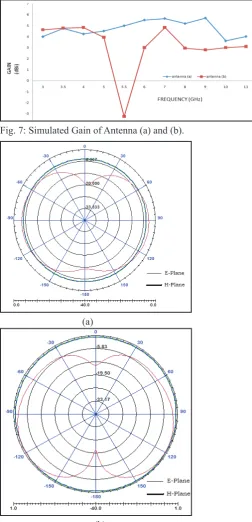
Similarly in UWB frequency range the constant gain also required for good response, Fig. 7 presents the simulated gain for antenna (a) and (b). The variation of antenna gain in the UWB band is about 2.5–5 dBi.
Fig. 7: Simulated Gain of Antenna (a) and (b).
(a)
(b)
(c)
Fig. 8: Simulated Radiation Far-Field Patterns for the Proposed Antenna Operation at (a) 3 GHz, (b) 8 GHz, and (c) 10 GHz
For briefness, the simulated E-plane and H-plane radiation patterns at 3, 8 and 10 GHz are shown in Fig. 8 (a) and (b) respectively. It is seen that this antenna has the almost omni-directional radiation pattern like normal monopole antennas. However, the omni-directional radiation properties have a little deterioration as frequency. Over the entire bandwidth, it is similar to a conventional wideband monopole antenna.
IV. Conclusion
A concise monopole dual Band antenna for dual Band applications has been designed and analysed with significant results. The matching bandwidth of the proposed antenna has been significantly improved by using FR4 substrate. By cutting a c-shape slot in the radiating band-rejected filtering properties in the WLAN band is achieved. Stable radiation patterns and stable gain in the UWB band are also obtained. Hence, this type of antenna can be used to avoid interferences from WiMAX and WLAN systems when they coexist with UWB services.
References
[1] D. Porcino, W. Hirt,“Ultra-wideband radio technology: Potential and challenges ahead”, IEEE Commun. Magazine, Vol. 41, No. 7, pp. 66–74, Jul. 2003.
[2] T. P. Vuong, A. Ghiotto, Y. Duroc, S. Tedjini,“Design and characteristics of a small U-slotted planar antenna for IR-UWB”, Microw. Opt. Technol. Lett., Vol. 49, pp. 1727–1731, Jul. 2007.
[3] Y. -J. Cho, K. -H. Kim, D. -H. Choi, S. -S. Lee, S. -O. Park,“A miniature UWB planar monopole antenna with 5-GHz band- rejection filter and the time-domain characteristics,” IEEE Trans. Antennas Propag., Vol. 54, pp. 1453–1460, May 2006.
[4] W. S. Lee, D. Z. Kim, K. J. Kim, J. W. Yu,“Wideband planar monopole antennas with dual band-notched characteristics”, IEEE Trans. Microw. Theory Tech., Vol. 54, pp. 2800–2806, Jun. 2006.
[5] Qing-Xin Chu, Ying-Ying Yang,“A Compact Ultrawideband Antenna With 3.4/5.5 GHz Dual Band-Notched Characteristics", IEEE Trans. Antennas Propagation, Vol. 56, No. 12, Decmber 2008.
Luis Jofre,“Integrated Bluetooth and UWB Antenna”, IEEE Antennas Propag letters, Vol. 8, 2009.
[7] J. Powell,“Antenna Design for Ultra Wideband Radio”, M.Sc. thesis Massachusetts Institute of Technology, Cambridge, MA, 2004.
[8] W. Wang, S. S. Zhong,“A broadband CPW-fed arrowlike printed antenna”, In Proc.IEEE AP-S Int. Symp., Jun. 2004, Vol. 1, pp.751–754.
[9] B. C. Wadell, Transmission Line Design Handbook. Boston, MA: Artech House, 1991, pp. 73–76.
[10] I. Pele, A. Chousseaud, S. Toutain,“Simultaneous modeling of impedance and radiation pattern antenna for UWB pulse modulation”, In Proc. IEEE AP-S Int. Symp., Jun. 2004, Vol. 2, pp. 1871–1874.
Sarita Singh received her B.Tech. degree in Electronics & Communication Engineering from Uttar Pradesh Technical University, Lucknow, India, in 2007, the M.Tech degree in Electronics & Communication Engineering from Rajeev Gandhi Proudhyogiki Vishwavidyalaya, Bhopal, India, in 2014. She was a lecturer in Department of electronics and Communication Engineering, G.B.Pant University, Pantnagar, in 2007. She is a Assistant Professor, in Department of Electronics and Communication Engineering, Bharat Institute of Technology (Affiliated to UPTU, Lucknow), Meerut, India, since August 2008. Her research interests include Antennas, Mobile & Wireless communication ,VLSI, and Computer Networking.