ANALYTICAL STUDY ON THE BEHAVIOUR
OF REINFORCED BEAM COLUMN JOINT
WITH PARTIAL REPLACEMENT OF GGBS
SLAG SUBJECTED TO CYCLIC LOADING BY
USING ANSYS CIVIL FEM
1V.Mohan Krishna,
2.M.Arun Kumar,
3P.Dileep Kumar
1Assistant Professor, 2Assistant Professor, 3Assistant Professor1Department of Civil Engineering,
1NBKR Institute of Science & Technology, Nellore, India
DOI: http://doi.one/10.1729/Journal.19965
Abstract:
This paper reports the study on the behavior of reinforced beam-column joint subjected to cyclic
loading with partial replacement of GGBS slag and theoretical investigation has been done along with
beam-column joints with hysteretic response on the structures. A model is developed to represent the response of
reinforced beam-column joints under cyclic loading by using ANSYS finite element software. Six experiments
were conducted on beam-column joint with and without GGBS. Out of the six specimens, two control specimens
were cast without GGBS and the other four specimens were cast with 40% GGBS. The specimens were tested
under constant axial load and varying lateral load.
The GGBS concrete specimens shows good seismic
performance as it has good energy absorption capacity as that of control specimens. It increase with 7.6% when
compared with the specimen without GGBS tested at 28days and also it increases with 20.73% when compared
with the specimen without GGBS tested at 56 days.
Thus 40% GGBS as replacement for cement can be used in
RC specimens as it showed good strength, ductility and energy absorption capacity.
The failure patterns are
concentrated in the joints and this is similar to the failure patterns obtained in ANSYS CIVIL FEM.
Key words - Reinforced Beam-column joint, GGBS slag, Finite element modelling, hysteretic curve.
I.INTRODUCTION
Now a days concrete is widely used construction material due to excellent in compressive strength and durability point of
view. Some of the recent studies in various parts of the world have revealed that Ground Granulated Blast furnace Slag (GGBS)
concrete can protect the steel reinforcement more efficiently, so that it can resist corrosion, and thus the structure as a whole, If
concrete is mixed with ground granulated blast furnace slag as a partial replacement for Portland cement, it would provide
environmental and economic benefits and the required workability, durability and strength necessary for the design of the structures
.
From structural point of view, GGBS replacement enhances lower heat of hydration, higher durability and higher resistance to
sulphate and chloride attack when compared with normal ordinary concrete. Typically , in modeling the reinforced concrete
structures under earthquake loading, it is assumed that beam-column joint remains elastic. Hysteretic behavior of structures
subjected to cyclic loads can be explained by the behavior of structures under earthquake load. If hysteretic loop is very narrow
and very low strength loop, it will accompanied by limited energy dissipation and ductility. While the wide loop and high strength
and high strength hysteretic loop represents the more ductility and energy dissipation..
The finite element modeling is used to find the effect of openings in reinforced concrete beams and to validate their experimental
performance. The finite element software package ANSYS CIVILFEM is used to create the models of the tested specimens of
beams. Using these models, the experimental behaviour of reinforced beam-column with partial replacement of GGBS slag
II.
Literature Review:
Elsewhere, Sharif et al (2010) have investigated the compressive strength properties when GGBFS is used to make concrete. The
uniaxial compression tests have been conducted on these concrete specimens with and without GGBFS at the ages of 3, 7, 28, 56,
90, 150 and 180 days. Increasing strength in concrete with GGBFS up to 40% to 60% and decreased afterwards. Among GGBFS
based concrete, at the age of 56 days, the concrete made with 40% replacement of cement by GGBFS attains higher compressive
strength as compared to the 20% and 60% GGBFS based concrete. Garcia et al (2009) have investigated the compressive strength
of the concrete containing ground granulated blast furnace slag of 230, 280 %, 50% and 70% of Portland cement. Siddique et al
(2011)investigated the compressive strength of concrete. The normal strength concrete and high-performance concretes (HPC) are
being used extensively in the construction of structures subjected to elevated temperatures. It deals with mechanical properties of
concrete made with ground granulated blast furnace slag subjected to temperatures up to 350ºC. The cement was replaced 0,20,40
&60% of GGBFS and the compressive strength was found out at 28days and 56days. Johari et al (2010) have investigated the
compressive strength of high strength concrete (HSC). They have studied influence of supplementary cementitious materials
(SCMs), namely silica fume, metakaolin, fly ash and ground granulated blast-furnace slag. Xue et al (2009)have investigated the
porosity and corrosion resistance of high performance concrete. The concrete were containing 10% of ground granulated
blast-furnace slag as Portland cement replacement. The experimental results show that the replacement of Portland cement by even such
a low amount of ground granulated blast furnace slag as environment more friendly and valuable alternative binder in properties
of hardened concrete mix. Bilim et al (2008) investigated the compressive strength of concrete. Data set of a laboratory work, in
which a total of 45 concretes were produced was utilised in artificial neural networks. Oner et al (2007) had investigated the
optimum level of GGBS on the compressive strength of concrete.
III. OBJECTIVES OF STUDY:
The Seismic performance of GGBS concrete beam column joint with a replacement percentage of 40% is to be studied in order to
utilize it in the building construction. The beam-column joint is to be modelled and analyzed using ANSYS CIVIL FEM.. The
reversed cyclic loads have to be established experimentally so that the beam-column experience substantial inelastic deformations
in tension and compression in the presence of axial loads, similar to those during earthquake.
• To model and analyse the beam-column joint by using the ANSYS CIVIL FEM.
• To design the mix for M40 grade concrete with 40% of GGBS as replacement of cement.
• To study the seismic performance of the beam-column joint by subjecting it to reversed lateral loads.
• The experimental results should be manipulated and analyzed by ANSYS CIVIL FEM and validated
IV.FINITE ELEMENT MODELLING
A three dimensional non-linear finite element model is developed by using ANSYS. To model the characteristics of concrete, a
eight node solid element, solid 65 is used. The solid element of eight nodes with three degrees of freedom at each nodal- translation
at the nodal x, y and z directions. The element is capable of plastic deformation, stimulating the cracking and crushing of concrete.
The William-varnk criterion is used for fracture modeling in concrete. The element is capable of accounting, for the cracking of
concrete in tension and compression. Some of the important parameters to perform the failure envelope in the model for elastic
modulus, uniaxial compressive strength, uniaxial tension strength and poissions ratio and shear transfer coefficients for open and
closed cracks. A bi-linear stress strain curve is used to model the material in both compression and tension and in any direction of
x, y and z. A multi-linear stress –strain curve is considered for the formation of stress-strain curve.
ELEMENTS TYPE USED IN THE MODEL
Concrete generally exhibits large number of micro cracks especially, at the interface between coarse aggregates and mortar even
BEAM188. The SOLID65 is used to model the concrete and BEAM188 element s used to model the reinforcement. The LINK8
element is used to combine the both SOLID65 and BEAM188 elements.
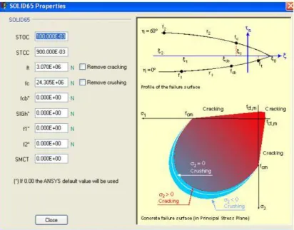
SOLID65 ELEMENT
ANSYS CIVLFEM provides a here-dimensional eight nodded solid isoperimetric element, SOLID65 is used to model concrete.
This element has eight nodes with three degrees of freedom of each node-translations in the nodal x, y and z direction. This
element is capable of plastic deformation, cracking n three orthogonal directions and crushing. A schematic diagram of the
element is shown n fig 4.1
Fig 4.1 SOLID 65 PROPERTIES
Fig 4.2. SOLID65 ELEMENT
BEAM188 ELEMENT
Fig 4.3 shows the details of BEAM188 is a linear (2-node) or a quadratic beam element in 3-D. This element has six degrees of freedom at each node, with the number of degrees of freedom depending on the value of KEYOPT(1), When KEYOPT (1) =0
(the default), six degrees of freedom occur at each node. These include translations in the x, y, and z directions and rotations
Fig.4.3. BEAM188 Geometry
V.ANSYS CIVILFEM MODELLING
Fig.5.1 and Fig.5.2 are the details of provided reinforcement of beam-column joint and beam cross-section is 200mmX150mm
and column cross-section is 150mmX150mm.
Whereas,
The bars used for providing reinforcement of beam column details are:
Main reinforcement provided for beam = 12mm and 10mm diameter bars
Main bars provided for column = 12mm diameter bars
Stirrup reinforcement provided for beam-column joint = 8mm diameter bars
.
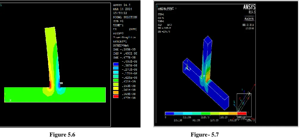
Figure 5.4 : Beam-column joint modelled in ANSYS. Figure 5.5 : Details of mesh model of beam-column joint.
Figure 5.6 Figure- 5.7
VI.MATERIALS USED IN INVESTIGATION
:
The different materials used in this investigation are
Cement (OPC 53 Grade)
Ground granulated blast furnace slag
Fine Aggregates
Coarse Aggregates (12.5 mm And 20 mm)
Water
Super plasticizer
Cement:
Fine Aggregate:
The fineaggregate that falls inzone-II conforming to IS 383-1970 was used. It has fineness modulus and specific gravity of 3.07
and 2.65.
Coarse Aggregate:
Crushed granite was used as coarse aggregate. The coarse aggregate was obtained from a local crushing unit having 20mm nominal
size, well graded aggregate according to IS: 383[20].The specific gravity was 2.8, while the bulk density was 1487 kg/m³.
Mineral admixtures: GGBS
Chemical composition
Ecocem GGBS comprises mainly ofCao,SIO2, Al2o3, Mgo, it contains less than 1% crystalline silica, and contains less than 1
ppm water soluble chromium IV. It has the same main chemical constituents as ordinary Portland cement, but in different
proportions:
in Table 6.1.
Table 6.1 chemical composition of GGBS
Chemical constituent Portland cement GGBS
Cao 65% 40%
Sio2 20% 35%
Al2o3 5% 10%
Mgo 2% 8%
Table 6.2 Physical Properties of GGBS
Particulars Property Particulars
Colour Off white powder Colour
Bulk density loose 1.0-1.1 tonnes/m³ Bulk density loose
Bulk density vibrated 1.2-1.3 tonnes/m³ Bulk density vibrated
Chemical admixtures: Super Plasticizer:
In the present investigation, GLENIUM B1-233 (BASF) Super plasticizer was used .It is used for commercial type high range water reducing agent suitable for fly ash concrete. GLENIUM B1-233 is free of chloride & low alkali. It is compatible with all types of cements as shown in
MIX DESIGN
This chapter deals with the mix design of concrete with and without GGBS.
Table 6.3 Mix design details of concrete with 40% GGBS
Particulars Values
Cement
249.98 kg/m 3
GGBS
166.656 kg/m 3
Fine aggregate
677.066 kg/m 3
Coarse aggregate
1221.44 kg/m 3
Water
166.656 kg/m 3
Super plasticizer 2.67kg/m3
Water-binder ratio 0.40
VII.RESULTS AND DISCUSSIONS
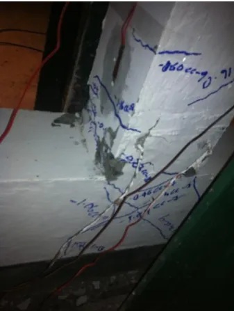
In the specimens without GGBS, failure was due to concrete crushing at the beam-column junction and minor cracks were noticed
along the height of the column. In the specimen with GGBS also failure was due to concrete crushing at the beam-column junction and minor cracks were noticed along the height of the column. The following Figure shows the failure pattern of beam-column
joint with and without GGBS.
Fig- 7.1- Specimen without GGBS Fig- 7.2. Specimen with 40% of GGBS
LATERAL LOAD VERSUS LATERAL DISPLACEMENT CURVE
The Hysteresis Curves are plotted for the variation of lateral displacement with that of the lateral load for all the specimens as shown
in Figure 7.1 & 7.2.
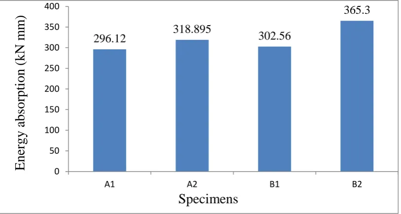
Fig. 7.3 Comparison of Peak lateral loads-lateral displacement Fig. 7.4 average energy absorption capacity for specimens
From the Figure 7.4, it is observed that the peak energy absorbed by the specimen with GGBS and tested at 56days is maximum
compared to all the specimens and is 23% is more when compared to the specimen series respectively.
-20 -15 -10 -5 0 5 10 15 20
-50 0 50
L
o
ad
(k
N
)
Displacement (mm)
A1-1 A2-1 A2-2 B1-1 B2-1 B2-2 0 50 100 150 200 250 300 3500 5 10 15
E
n
er
g
y
abs
o
rp
ti
o
n
(k
N
m
m
)
Number of cycles
Fig. 7.5 Comparison of total energy absorption Capacity of specimen
VIII.CONCLUSIONS
Thus 40% GGBS as replacement for cement can be used in RC specimens as it showed good strength, ductility and
energy absorption capacity. The failure patterns are concentrated in the joints and this is similar to the failure patterns
obtained in ANSYS CIVIL FEM.
The load carrying capacity of the specimens with GGBS and tested at 28 days increases by 6.6% when compared
with specimens without GGBS and increases by 3.5% when compared with specimen without GGBS at 56 days
tested.
The specimens with 50% GGBS shows adequate ductility when tested at 28 days and 56 days.
The GGBS concrete specimens shows good seismic performance as it has good energy absorption capacity as that
of control specimens. It increase with 7.6% when compared with the specimen without GGBS tested at 28days and
also it increases with 20.73% when compared with the specimen without GGBS tested at 56 days.
REFERENCES
1. Cahit bilim, “Predicting The Compressive Strength Of Ground Granulated Blast Furnace Slag Concrete Using Artificial
Neural Network”, Construction And Building Materials,(2008), vol.29, pp533-540.
2. Eva Vejmelková and Milena Pavlíková,. “High Performance Concrete Containing Lower Slag Amount: A Complex View
Of Mechanical And Durability Properties”, Construction And Building Materials, (2009), vol.23, pp 2237-2245.
3. Gengying Li and Xiaohua Zhao, “Properties Of Concrete In Corporating Fly ash and Ground Granulated Blast Furnace
Slag”, Cement And Concrete Composites, (2002), vol.29, pp 505-514.
4. Hans Beushausen and Mark Alexander,. “Early-Age Properties, Strength Development And Heat Of Hydration Of
Concrete Containing Various South African Slags At Different Replacement Ratios”, Construction And Building
Materials, (2011), vol.29, pp533-540.
5. Isa Yuksel and Turhan Bilir, “Durability Of Concrete Incorporating Non-Ground Blast Furnace Slag And Bottom Ash As
Fine Aggregate”,Building And Environment, (2006), vol.42, pp 2651-2659
6. Ganesh Babu.K and Sree Rama Kumar, “Efficiency Of GGBS In Concrete”, Cement And Concrete Research, (2000),
vol.30, pp 1031-1036.
7. Kyong Yun Yeau and Eun Kyum Kim, “An Experimental Study On Corrosion Resistance Of Concrete With Ground
Granulated Blast- Furnace Slag”, Cement And Concrete Research, (2004), vol.3, pp 45-51.
8. Li-Ping Gu and Bo Liu , “Study On The Flexural Fatigue Performance And Fractal Mechanism Of Concrete With High
Proportions Of Ground Granulated Blast-Furnace Slag”, Cement And Concrete Research, (2006), vol.37, pp 242-250
296.12
318.895
302.56
365.3
0 50 100 150 200 250 300 350 400A1 A2 B1 B2
9. Megat Johari.V , Brooks J.J, Shahid Kabir, Patrice Rivard,. “Influence Of Supplementary Cementitious Materials On
Engineering Properties Of High Strength Concrete”,Construction And Building Materials, (2011), vol.25, pp 2639-2648.
10. Mohd Shariq and Amjad Masood, Effect Of GGBS On Time Dependent Compressive Strength Of Concrete. Cement And
Concrete Research, (2010), vol.3, pp 45-51
11. Oner.A and Akyuz.S, “An Experimental Study On The Optimum Usage Of GGBS For The Compressive Strength Of
Concrete”,Cement And Concrete Composites, (2004), vol.29, pp 505-514.
12. Qiang Wang and Peiyu Yan , “Effect Of Blended Steel Slag GBFS Mineral Admixture On Hydration And Strength Of
Cement”, Constuction And Building Materials, (2010), vol.24, pp 1469-1478.
13. Rafat Siddique and Deepinder Kaur, “Properties Of Concrete Containing Ground Granulated Blast Furnace Slag (GGBFS)
At Elevated Temperatures”, Journal Of Advanced Research, (2011), vol.3, pp 45-50.
14. Pal S.c, and Mukherjee.A, “Investigation Of Hydraulic Activity Of Ground Granulated Blast Furnace Slag In Concrete”,
Cement And Concrete Research, (2003), vol.30 , pp 1481-1486.
15. Sioulas.B and G. Sanjayan,. “Hydration Temperatures In Large High Strength Concrete Columns Incorporating Slag”,