R E S E A R C H
Open Access
A novel simultaneous dynamic range
compression and local contrast enhancement
algorithm for digital video cameras
Chi-Yi Tsai
*and Chien-Hsing Chou
Abstract
This article addresses the problem of low dynamic range image enhancement for commercial digital cameras. A novel simultaneous dynamic range compression and local contrast enhancement algorithm (SDRCLCE) is presented to resolve this problem in a single-stage procedure. The proposed SDRCLCE algorithm is able to combine with many existent intensity transfer functions, which greatly increases the applicability of the proposed method. An adaptive intensity transfer function is also proposed to combine with SDRCLCE algorithm that provides the capability to adjustably control the level of overall lightness and contrast achieved at the enhanced output. Moreover, the proposed method is amenable to parallel processing implementation that allows us to improve the processing speed of SDRCLCE algorithm. Experimental results show that the performance of the proposed method outperforms three state-of-the-art methods in terms of dynamic range compression and local contrast
enhancement.
Keywords:low dynamic range image enhancement, dynamic range compression, local contrast enhancement, sta-tistics of visual representation, quantitative evaluation.
1. Introduction
In recent years, digital video cameras have been employed not only for video recording, but also in a variety of image-based technical applications such as visual tracking, visual surveillance, and visual servoing. Although video capture becomes an easy task, the images taken from a camera usually suffer from certain defects, such as noises, low dynamic range (LDR), poor contrast, color distortion, etc. As a result, the study of image enhancement to improve visual quality has gained increasing attention and becomes an active area in image and video processing researches [1,2]. This article addresses two common defects: LDR and poor contrast. Several existing methods have provided functions of dynamic range compression and image contrast enhancement, but there is always room for improve-ment, especially in computational efficiency for real-time video applications.
For dynamic range compression, it is well known that the human vision system involves several sophisticated processes and is able to capture a scene with large dynamic range through various adaptive mechanisms [3,4]. In contrast, current video cameras without real-time enhancement processing generally cannot produce good visual contrast at all ranges of image signal levels. Local contrast often suffers at both extremes of signal dynamic range, i.e., image regions where signal averages are either low or high. Hence, the objective of dynamic range compression is to improve local contrast at all regional signal average levels within the 8-bit dynamic range of most video cameras so that image features and details are clearly visible in both dark and light zones of the images. Various dynamic range compression techni-ques have been proposed, and the reported methods can be categorized into two groups based on the purpose of application.
The first group of dynamic range compression meth-ods aims to reproduce undistorted high-dynamic range (HDR) still images, which are usually stored in a float-ing-point format such as the radiance RGBE image
* Correspondence: [email protected]
Department of Electrical Engineering, Tamkang University, 151 Ying-chuan Road, Danshui District, New Taipei City 251, Taiwan, R.O.C
format [5], on LDR display devices (the so-called HDR image rendering problem) [6-8]. Reinhard et al. [6] developed a tone reproduction operator based on the time-tested techniques of photographic practice to pro-duce satisfactory results for a wide variety of images. Meylan and Süsstrunk [7] proposed a spatial adaptive filter based on center-surround Retinex model to render HDR images with reduced halo artifacts and chromatic changes. Recently, Horiuchi and Tominaga [8] devel-oped a spatially variant tone mapping algorithm to imi-tate S-potential response in human retina for enhancing HDR image quality on an LDR display device. The sec-ond group aims to enhance the visual quality of degraded LDR images or videos recorded by imaging devices of limited dynamic range (the so-called LDR image enhancement problem), and the techniques devel-oped in first group may not be suitable to deal with this problem due to different purpose. Traditionally, the pur-pose of LDR image/video enhancement can be simply achieved by adopting a global intensity transfer function that maps a narrow range of dark input values into a wider range of output values. However, the traditional method will decrease the visual quality in the bright region due to a compressed range of bright output values. This drawback motivates the requirement of more advanced algorithms to improve LDR image/video enhancement performance. For instance, to improve the visual quality of underexposed LDR videos, Bennett and McMillan [9] proposed a video enhancement algorithm called per-pixel virtual exposures to adaptively and inde-pendently vary the exposure at each photoreceptor. The reported method produces restored video sequences with significant improvement; however, this method requires large amount of computation and is not amen-able to practical real-time processing of video data.
To preserve important visual details, the techniques developed in second group are usually combined with a local contrast enhancement algorithm. For local contrast enhancement, histogram equalization (HE)-based con-trast enhancement algorithms, such as adaptive HE (AHE) [10] and contrast-limited AHE [11], are well established for image enhancement. However, the exis-tent HE-based methods generally produce strong con-trast enhancement and may lead to excessive artifacts when processing color images. To achieve local contrast enhancement with reduced artifacts, Tao and Asari [12] proposed an AINDANE algorithm which is comprised of two separate processes, namely, adaptive luminance and adaptive contrast enhancements. The adaptive luminance enhancement is employed to compress the dynamic range of the image and the adaptive contrast enhance-ment is applied to restore the contrast after luminance enhancement. The authors also developed a similar but efficient nonlinear image enhancement algorithm to
enhance the image quality for improving the perfor-mance of face detection [13]. However, the common drawback of these two methods is that the procedure is separated into two stages and may induce undesired arti-facts in each stage. Retinex-based algorithms, such as multi-scale Retinex (MSR) [14] and perceptual color enhancement [3,4,15], are effective techniques to achieve dynamic range enhancement, local contrast enhance-ment, and color consistency based on Retinex theory [16], which describes a model of the lightness and color perception of human vision. However, Retinex-based algorithms are usually computational expensive and require hardware acceleration to achieve real-time per-formance. Monobe et al. [17] proposed a spatially variant dynamic range compression algorithm with local contrast preservation based on the concept of local contrast range transform. Although this method performs well for enhancement of LDR images, the image enhancement procedure is transformed to operate in logarithmic domain. This requirement takes high computational costs with a large memory and leads to an inefficient algorithm. Recently, Unaldi et al. [18] proposed a fast and robust wavelet-based dynamic range compression (WDRC) algorithm with local contrast enhancement. The authors also extended WDRC algorithm to combine with a linear color restoration process to cope with color constancy problem [19]. The main advantage of WDRC algorithm is that the processing time can be reduced rapidly since WDRC algorithm fully operates in the wavelet domain. However, WDRC algorithm empirically produces weak contrast enhancement and could not pre-serve visual details for LDR images.
This article addresses the problem of LDR image enhancement for digital video cameras. From the litera-ture discussed above, we note that a challenge in the design of LDR image enhancement is to develop an effi-cient spatially variant algorithm for both dynamic range compression and local contrast enhancement. This pro-blem motivates us to derive a new simultaneous dynamic range compression and local contrast enhance-ment (SDRCLCE) algorithm to resolve LDR image enhancement problem in spatial domain efficiently. To do so, we first propose a novel general form of SDRCLCE algorithm whose use is compatible with any monotonically increasing and continuously differentiable intensity transfer function. Based on this general form, an adaptive intensity transfer function is then proposed to select a proper intensity mapping curve for each pixel depending on the local mean value of the image. The main difference between the proposed method and other existent approaches is summarized as follows.
combine with many existent intensity transfer func-tions, such as the typical gamma curve, to achieve the purpose of LDR image enhancement. Thus, the applicability of the proposed method is greatly increased.
(2) The proposed SDRCLCE method fully operates in spatial domain, and the process is amenable to parallel processing. From the implementation point of view, this feature allows the proposed method to be faster on dual core processors and improves the computational efficiency in practical applications. (3) The proposed adaptive intensity transfer function is a spatially variant mapping function associated with the local statistical characteristics of the image. Therefore, unlike wavelet-based approaches [18,19], the proposed method is able to produce satisfactory contrast enhancement for preserving visual details of LDR images.
(4) By combining the proposed adaptive intensity transfer function with SDRCLCE algorithm, the pro-posed method possesses the adjustability to
sepa-rately control the level of dynamic range
compression and local contrast enhancement. This advantage improves flexibility of the proposed method in practical applications.
In the experiments, the performance of the proposed SDRCLCE method is compared with three state-of-the-art methods, both quantitatively and visually. Experi-mental results show that the proposed SDRCLCE method outperforms all of them in terms of dynamic range compression and local contrast enhancement.
The rest of this article is organized as follows. Section 2 describes the derivation of the general form of the proposed SDRCLCE algorithm. Section 3 presents the design of the proposed method. A novel adaptive inten-sity transfer function will be proposed. Section 4 devises a linear color remapping algorithm to preserve the color information of the original image in the enhancement process. Experimental results are reported in Section 5. Extended discussion of several interesting experimental observations will be presented. Section 6 concludes the contributions of this article.
2. Derivation of the general form of SDRCLCE algorithm
This section presents the derivation of the proposed method to simultaneously enhance image contrast and dynamic range. A local contrast preserving condition is first introduced. The general form of SDRCLCE algo-rithm is then derived based on this condition. Finally, the framework of SDRCLCE algorithm is presented to explain the parallelizability of the proposed method.
2.1. Image enhancement with local contrast preservation
Since human vision is very sensitive to spatial frequency, the visual quality of an image highly depends on the local image contrast which is commonly defined by using Michelson or Weber contrast formula [20]. In this article, the Weber contrast formula is utilized to derive the condition of local image contrast preservation.
Let Iin(x, y) and Iavg(x, y), respectively, denote the input luminance level and the corresponding local aver-age one of each pixel (x, y). The Weber contrast formula is then given by [20]
ContrastWeber(x,y) =I−avg1(x,y)[Iin(x,y)−Iavg(x,y)],(1)
where ContrastWeberÎ[-1, +∞) is the local contrast value of the input luminance image. Based on the Weber contrast value (1), the local contrast preserving condition of a general image enhancement processing is described as follows
g−avg1(x,y)[gout(x,y)−gavg(x,y)] =
I−avg1(x,y)[Iin(x,y)−Iavg(x,y)], (2)
where gout(x, y) andgavg(x, y), respectively, denote the contrast enhanced output luminance level and the cor-responding local average one of each pixel (x, y). Oper-ating on expression (2) bygavg(x, y) gives
gout(x,y) = [I−avg1(x,y)gavg(x,y)]Iin(x,y), (3)
wheregavg(x, y) usually is a function ofIin(x, y). There-fore, expression (3) presents a basic form in the spatial domain for image enhancement with local contrast preservation.
2.2. The general form of SDRCLCE algorithm
In this section, the basic form (3) is applied to the dynamic range compression with local contrast enhancement for color images. In traditional dynamic range compression methods, the remapped luminance image, denoted by yT (x, y), is usually obtained from a fundamental intensity transfer function such that
yT(x,y) =T[Iin(x,y)], (4)
whereT[•]ÎC1 is an arbitrary monotonically increas-ing and continuously differentiable intensity mappincreas-ing curve. According to expression (4), the output local average luminance level of each pixel can be approxi-mated by using the first-order Taylor series expansion such that (see Appendix)
gavg(x,y) =T[Iin(x,y)]+
whereT[Iin(x,y)] = dT[X]
dXX=I
in(x,y). By substituting
(5) into (3), the basic formula of dynamic range com-pression with local contrast preservation is obtained as follows.
gout(x,y) =¯Iin(x,y)×T[Iin(x,y)]+ [1− ¯Iin(x,y)]×
T[Iin(x,y)]Iin(x,y)
=¯Iin(x,y)×yT(x,y)+
[1− ¯Iin(x,y)]×ylcp(x,y),
(6)
wheregout(x, y) denotes the enhanced output lumi-nance level of each pixel, ylcp (x, y) =T[Iin(x, y)]Iin(x, y)≥0 is the component of local contrast preservation, and ¯Iin(x,y) =Iin(x,y)
Iavg(x,y)for Iavg (x, y) ≠0 is a weighting coefficient which ranges from 0 to 256. Expression (6) shows that when ¯Iin(x,y)∼= 0the local contrast preservation component ylcp (x, y) dominates the enhanced outputgout(x, y). On the other hand, when
¯
Iin(x,y)∼= 1the output in (6) is close to the fundamental intensity mapping result yT (x, y). Otherwise, the
enhanced output gout(x, y) is a linear combination between the fundamental intensity mapping component yT(x, y) and the local contrast preservation component
ylcp(x, y).
In order to achieve local contrast enhancement, one of the common used enhancement schemes is the linear unsharp masking (LUM) algorithm, which enhances the local contrast of output image by amplifying high-fre-quency components such that [21]
yLUM(x,y) =Iin(x,y) +λIhigh(x,y)
=Iin(x,y) +λ[Iin(x,y)−Iavg(x,y)],
(7)
where Ihigh (x, y) = Iin (x, y)-Iavg (x, y) denotes the high-frequency components of input image, and lis a nonnegative scaling factor that controls the level of local contrast enhancement. Based on the concept of LUM algorithm, we modify the output local average lumi-nance (5) into an unsharp masking form such that
gavg(x,y) =T[Iin(x,y)]−αT[Iin(x,y)]Ihigh(x,y), (8)
where a = {-1, 1} is a two-valued parameter that
determines the property of contrast enhancement. Whena= 1, expression (8) is equivalent to (5) that pro-vides local contrast preservation for the output local average luminance. In contrast, whena= -1, expression (8) becomes a LUM equation withl=T’[Iin(x, y)]≥ 0 to achieve local contrast enhancement of output local average luminance.
Next, substituting (8) into (3) yields the basic formula of dynamic range compression with local contrast enhancement such that
gout(x,y) =¯Iin(x,y)×yT(x,y)+
α[1− ¯Iin(x,y)]×ylcp(x,y), (9)
where the parameters ¯Iin(x,y), ylcp (x, y), and a are previously defined in equations (6) and (8). According to expression (9), the general form for SDRCLCE algo-rithm is then obtained as follows:
gout(x,y) =
f−1
n (x,y){¯Iin(x,y)×yT(x,y)+
[1− ¯Iin(x,y)]×ylce(x,y)}
1
0 , (10a)
fn(x,y) =
¯
Imaxin (x,y)×T(I max in )+
[1− ¯Iinmax(x,y)]×[αT(I max in )I
max in ]
1
ε
,(10b)
ylce(x,y) =α×ylcp(x,y)
=αT[Iin(x,y)]Iin(x,y) for α={−1, 1} (10c)
where ylce (x, y) denotes the component of local con-trast enhancement for each pixel,Imaxin is the maximum value of the luminance signal, ¯Imaxin (x,y) =Imaxin I−avg1(x,y) for Iavg (x, y)≠0 is the weighting coefficient with respect to the maximum luminance value, fnÎ [ε, 1] denotes a normalization factor to normalize the output, and εis a small positive value to avoid dividing by zero. The operator{x}bameans that the value of xis bounded to the range [a,b]. In expression (10c), the parameterais set to 1.0 for the purpose of local contrast preservation and is set to -1.0 for the purpose of local contrast enhancement. Therefore, expression (10), referred to as the general form of SDRCLCE algorithm, provides the capability to achieve dynamic range compression and local contrast enhancement simultaneously.
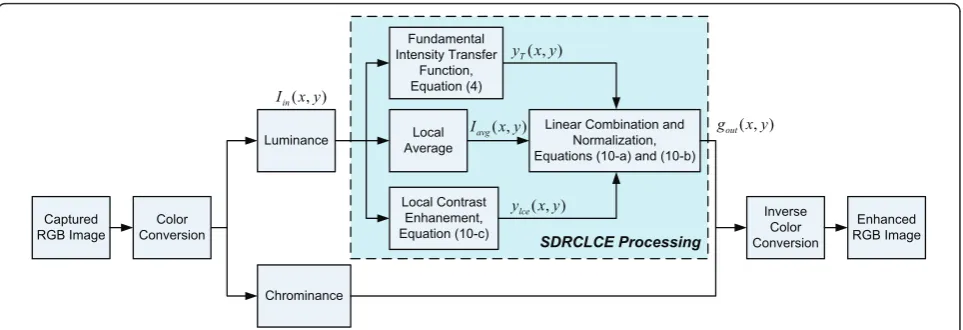
image with the original chrominance component, the enhanced image is obtained through an inverse color space transform or a linear color remapping process which will be presented in next section. As can be seen in Figure 1, the computations of the remapped lumi-nance image, the local contrast enhancement, and the local average luminance image can be performed indivi-dually. This implies that the proposed SDRCLCE algo-rithm is amenable to parallel processing implementation and could be faster on dual core processors. This feature will be validated in the experiments.
3. The proposed algorithm
As discussed in the previous section, once any intensity transfer functionT[Iin(x, y)] defined in (4) is determined, the proposed SDRCLCE equation (10) can be applied to the intensity transfer function and realize the function of SDRCLCE. This implies that the enhanced output of the proposed SDRCLCE algorithm is characterized by the selected intensity transfer function. Therefore, the selection of a suitable intensity transfer function is an important task before applying SDRCLCE algorithm. In this section, a novel intensity transfer function is first presented. The proposed algorithm is then derived based on SDRCLCE equation (10).
3.1. Adaptive intensity transfer function
The intensity transfer function realized in the proposed algorithm is a tunable nonlinear transfer function for providing dynamic range adjustment adaptively. To achieve this, a hyperbolic tangent function is adopted for satisfying the condition of monotonically increasing and continuously differentiable. Moreover, another advantage of the hyperbolic tangent function is that the output value ranges from 0 to 1 for any positive input value, which guarantees that the output always lies within a desired range of value.
The proposed intensity transfer function is an adaptive hyperbolic tangent function based on the local statistical characteristics of the image. This function aims to enhance the low intensity pixels while preserving the stronger pixels as defined by
ytanh(x,y) =T[Iin(x,y)] = tanh
Iin(x,y)m−1(x,y) ,(11)
where the parameter m(x, y) controls the curvature of the hyperbolic transfer function and is calculated based on the local statistical characteristics of the image. Since the simplest local statistical measure of the image is the local mean in a local window, the parameterm(x, y) is defined as a linear function associated with the local mean of the image such that
m(x,y) =Iavg(x,y)×S+mmin, (12)
whereS= (Imaxin )−1(mmax−mmin)is a scale factor, and (mmin, mmax) are two nonzero positive parameters satis-fying 0 <mmin <mmax.Iavg(x, y) =Iin (x, y)⊗FLPF(x, y) is the local average of the image, where the operator⊗ denotes the 2D convolution operation, andFLPF(x, y) denotes a spatial low-pass filter kernel function and is subject to the condition
FLPF(x,y)dxdy= 1. (13)
Expression (12) implies that the value of m(x, y) is bounded to the range [mmin,mmax], and thus the curva-ture of (11) can be determined by the two parameters mminandmmax.
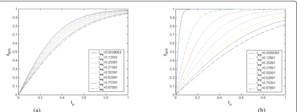
Figure 2a, shows the plot of intensity mapping curve processed by expressions (11) and (12) for the two para-meters mmin and mmax set as (100/255, 150/255) and (10/255, 250/255), respectively. These figures illustrate how the curvature of the intensity transfer function (11) changes as for various values of m(x, y). It is clear in Captured RGB Image Local Average Luminance Chrominance Local Contrast Enhanement, Equation (10-c) ) , (x y Iin
) , (x y Iavg
) , (x y ylce
) , (x y yT Fundamental Intensity Transfer
Function, Equation (4)
Linear Combination and Normalization, Equations (10-a) and (10-b)
) , (x y gout Enhanced RGB Image SDRCLCE Processing Color Conversion Inverse Color Conversion
both figures that the curvature of the processed intensity mapping curve changes for each pixel depending on the local mean value m(x, y). More specifically, when the local mean value of the input pixel is small, the pro-posed intensity transfer function (11) inclines to provide an intensity mapping curve with large curvature for enhancing the intensity of the input pixel. In contrast, a pixel with large local mean value leads an intensity map-ping curve with small curvature in this process for pre-serving the intensity as much the same as the original one.
Moreover, comparing Figure 2a with 2a, one can see that the two parametersmminandmmax determine the maximum and minimum curvatures of the processed intensity mapping curve, respectively. In other words, a smaller value ofmminleads to a steeper tonal curve pro-viding more LDR compression, and a larger value of
mmax leads to a flatter tonal curve providing more
dynamic range preservation. However, one problem shown in Figure 2 is that the maximum value ofytanh (x, y) obtained from (11) will be less than the maximum value of Iin (x, y) when increasing the value of mmax. This problem can be resolved by normalizing (11) such that
ynormaltanh (x,y) =T−1(Imaxin ) tanhIin(x,y)m−1(x,y) ,(14)
where T(Imaxin ) = tanhIinmaxm−1(x,y) is a normalizing factor to ensure that ynormaltanh (x,y) = 1 when
Iin(x,y) =Imaxin . Although the intensity transfer function (14) satisfies the condition of monotonically increasing and continuously differentiable, the derivative of (14)
becomes relatively complex sincem(x, y) is a function of Iin(x, y). In the remainder of this article, therefore, the adaptive intensity transfer function (11) is utilized to combine with the proposed SDRCLCE algorithm, which also resolves the problem mentioned above.
3.2. Application of SDRCLCE algorithm into the adaptive intensity transfer function
Since the adaptive intensity transfer function (11) is continuously differentiable, the proposed SDRCLCE equation (10) can be applied to this function accord-ingly. First of all, the differential function of the adaptive intensity transfer function (11) is given by
T[Iin(x,y)] =
1−tanh2Iin(x,y)m−1(x,y) ×
[m(x,y)−SwmaxIin(x,y)]m−2(x,y), (15)
where wmax denotes the maximum value of the
coefficients in the low-pass filter mask. Next, the nor-malization factor fn is calculated according to the
expression (10b) such that
fn(x,y) = ¯
Imaxin (x,y)×tanh
Iin(x,y)m−1(x,y) + [1− ¯Imax
in (x,y)]×[αT(Imaxin )Imaxin ]
1
ε
,(16)
T(Imaxin ) =1−tanh2Imaxin m−1(x,y) ×
[m(x,y)−SwmaxImaxin ]m−2(x,y),
where the parameters a, Imaxin , and I¯maxin (x,y)are pre-viously defined in Equation 10b. Finally, substituting
(a) (b)
(11), (15), and (16) into (10a) yields the SDRCLCE out-put such that
gtanh(x,y) =
fn−1(x,y)
¯
Iin(x,y)×ytanh(x,y)+
[1− ¯Iin(x,y)]×ylce(x,y)
1
0
, (17)
where ¯Iin(x,y)and ylce (x, y) denote the weighting coefficient and the local contrast enhancement compo-nent previously defined in Equations 6 and 10c, respectively.
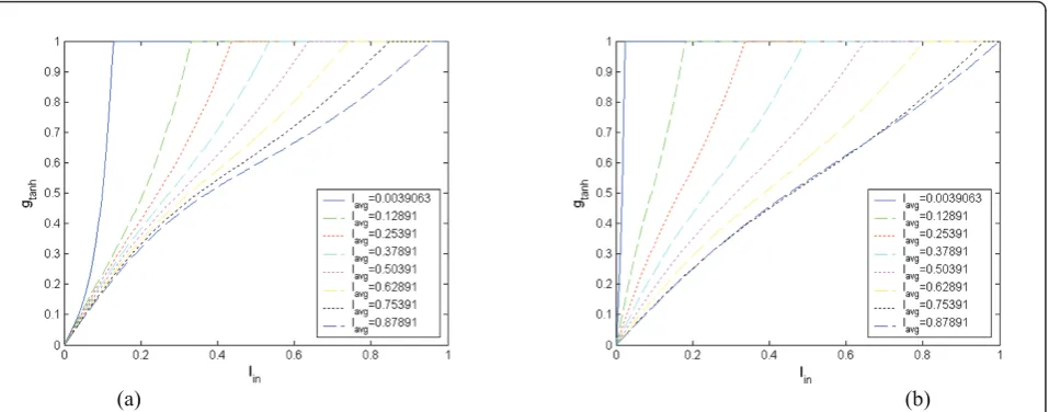
Figures 3 and 4, respectively, illustrate the intensity mapping curve processed by expression (17) for a= 1 anda = -1 with tweaking the parameterm(x, y). Since the value of m(x, y) depends on the two parameters
mmin andmmax, these figures show how the parameters (mmin, mmax) affect the results of the processed inten-sity mapping curve. In Figure 3a, b, the parameters (mmin, mmax) are set as (100/255, 150/255) and (10/ 255, 250/255), respectively. Comparing Figure 3a with
3b, one can see that the parameter mmin determines
the LDR compression capability in the dark part of the image. For instance, decreasing mmin would increase the slope of the tonal curve thereby enhancing the intensity of the darker pixel. On the other hand, the parameter mmax determines the contrast preservation capability in the light part of the image. Increasing mmax would decrease the slope of the tonal curve that preserves the intensity of the brighter pixel, for
(a) (b)
Figure 3The intensity mapping curve processed by expression (20) fora= 1 with (a) (mmin,mmax) = (100/255, 150/255), and (b) (mmin,mmax) = (10/255, 250/255).
(a) (b)
example. This means that the amount of lighting and contrast preservation for the overall enhancement can
be controlled by adjusting the parameters (mmin,
mmax). Figure 4 shows a similar result; however, the processed intensity mapping curve provides the con-trast stretching capability to enhance the local concon-trast of the image. The amount of lighting and contrast stretching for overall enhancement can also be con-trolled by tailoring the parameters (mmin, mmax). In Section 5, the properties of the proposed adaptive intensity transfer function discussed above will be vali-dated in the experiments.
4. SDRCLCE algorithm with linear color remapping
An issue in the proposed SDRCLCE algorithm presented in the previous section is that the process only consists of luminance component without chrominance ones. This may result the color distortion problem in the enhance-ment process. In this section, the proposed SDRCLCE algo-rithm is extended to combine with a linear color remapping algorithm, which is able to preserve the color information of the original image in the enhancement process.
4.1. Linear remapping in RGB color space
In order to recover the enhanced color image without color distortion, a common method is to use the modi-fied luminance while preserving hue and saturation if HSV color space is used. However, if RGB coordinates are required, a simplified multiplicative model based on the chromatic information of the original image can be applied to recover the enhanced color image with mini-mum color distortion.
It PinRGB=Rin GinBin
T
and PRGBout =RoutGoutBout
T
denote the input and output color values of each pixel in RGB color space, respectively, then, the multiplicative model of linear color remapping in RGB color space is expressed as:
PoutRGB(x,y) =β(x,y)×PinRGB(x,y), (18)
whereb(x, y) ≥0 is a nonnegative mapping ratio for each color pixel (x, y), and it is usually determined by the luminance ratio such that
β(x,y) =gout(x,y)I−in1(x,y), (19)
where Iin(x, y) andgout(x, y) are the input and output luminance values corresponding to the color pixel
PinRGB(x,y)andPRGBout (x,y), respectively. Therefore, substi-tuting (17) and (19) into (18), the proposed SDRCLCE method is able to preserve hue and saturation of the ori-ginal image in the enhanced image.
4.2. Linear remapping in YCbCrcolor space
Although the linear RGB color remapping method (18) provides an efficient way to preserve the color informa-tion of the input color, YCbCr is the most commonly used color space to render video stream in digital video standards. Most video enhancement methods are pro-cessing in YCbCr color space; however, they usually result with less saturated colors due to only enhancing
Y component while leaving Cb, Cr components
unchanged. This problem motives us to perform the lin-ear color remapping method in YCbCr color space to minimize color distortion during video enhancement process.
Let PYCbCr
in =
YinCbinCrin
T
and
PYCbCr
out =
YoutCboutCrout
T
denote the input and output color values of each pixel in YCbCrcolor space, respec-tively. According to the ITU-R BT.601 standard [22], the color space conversion between RGB and YCbCrfor digital video signals is recommended as:
PinRGB(x,y) =A[PYCbCr
in (x,y)−D], (20)
PYCbCr
out (x,y) =A−1PRGBout (x,y) +D, (21)
where the transformation matrices AandA-1and the translation vectorDare given by
A= ⎡
⎣1.1641.164−0.3910 −1.5960.813 1.164 2.018 0
⎤ ⎦,
A−1=
⎡
⎣−0.25700.1482−0.50440.2910 0.43920.0977 0.4392 −0.3679−0.0713
⎤ ⎦,
D= ⎡ ⎣12816
128 ⎤ ⎦.
Substituting (20) into (17) yields
PoutRGB(x,y) =β(x,y)×A[PYCbCr
in (x,y)−D]. (22)
Then, the linear YCbCr color remapping method is obtained by substituting (22) into (21) so that
PYCbCr
out (x,y) =β(x,y)×[P YCbCr
in (x,y)−D] +D =β(x,y)×PYCbCr
in (x,y)+ [1−β(x,y)]×D,
(23)
More specifically, the remapping of luminance and chrominance (or colour-difference) components of each pixel are, respectively, given by
Yout(x,y) =β(x,y)×Yin(x,y)+
Ciout(x,y) =β(x,y)×Ciin(x,y)+
128×[1−β(x,y)], (25)
where Ydenotes the luminance component, andCi=
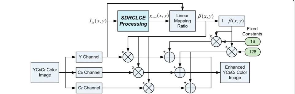
{Cb, Cr} denotes the chrominance one. Observing expressions (24) and (25), it shows that the linear color remapping in YCbCrcolor space requires an extra trans-lation determined by a scalar 1- b(x, y) and two fixed constants: 16 for luminance and 128 for chrominance. This is the main difference between RGB and YCbCr color remapping methods.
Figure 5 illustrates the framework of the proposed SDRCLCE algorithm combined with linear YCbCrcolor remapping method. In Figure 5, the SDRCLCE proces-sing block performs the proposed SDRCLCE algorithm as Figure 1 indicated to calculate the enhanced output luminance image. The luminance mapping ratio is then determined according to expression (19). Finally, the remapping of luminance and chrominance components is computed based on expressions (24) and (25), respec-tively. Figure 5 shows that the proposed method is able to directly operate on YCbCrsignals without color space conversion, which greatly improves the computational efficiency during video processing.
5. Experimental results
In this section, we focus on four issues, which include a detailed examination of the properties of the proposed method, the quantitative comparison with three state-of-the-art enhancement approaches, the visual comparison with the results produced by these methods, and com-putational speed evaluation.
5.1. Properties of the proposed method
In the property evaluation of the proposed method, the parametera defined in (10c) is set to -1.0 for the pur-pose of local contrast enhancement. In order for the
proposed method to compute the local average of the image Iavg(x, y) defined in (12), a spatial low-pass filter that satisfies the condition (13) is required. In the experiments, a Gaussian filter is utilized as a low-pass filter given by
FLPF(x,y) =Ke−
(x2+y2)(Sigma)2
, (26)
whereKis a scalar to normalize the sum of filter coef-ficients to 1, and Sigma denotes the standard deviation of Gaussian kernel. Based on the expressions (12) and (26), the proposed method controls the level of image
enhancement depending on three parameters: mmin,
mmax, and Sigma. Since the value of these three para-meters may drastically influence enhancement perfor-mance, it is interesting to study how they affect the enhancement results of the proposed method. In the fol-lowing, a study on the experiment of tweaking para-meters mmin, mmax, and Sigma is presented to achieve this purpose.
The parameter tweaking experiment consists of three experiments listed below:
(1) tweakingmminwith fixedmmaxand Sigma; (2) tweakingmminwith fixedmmaxand Sigma; and (3) tweakingSigmawith fixedmminandmmax.
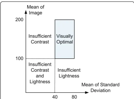
In these experiments, a quantitative method to quantify the performance of image enhancement approaches depending on the statistics of visual representation [23] is introduced to investigate the influence of tweaking para-meters on enhancement performance. Figure 6 illustrates the concept of the statistics of visual representation, which is comprised of the global mean of the image and the global mean of regional standard deviation of the image. This quantitative method is an efficient way to quantitatively evaluate the image quality after image enhancement in a 2D contrast-lightness map, in which the contrast and lightness of the image are measured by
YCbCr Color Image
) , (x y Iin
) , (x y gout
Enhanced YCbCr Color
Image SDRCLCE
Processing
Y Channel
Cb Channel
Cr Channel
Linear Mapping
Ratio
) , (x y E
) , ( 1E x y
x x x + + + x x 16 128 Fixed Constants
the mean of standard deviation and the mean of image, respectively. In [23], the authors found that the visually optimized images do converge to a range of approxi-mately 40-80 for global mean of regional standard devia-tion and 100-200 for global mean of the image, and they termed this range as thevisually optimal(VO) region of visual representation. More specifically, if the statistics point of an image falls in the rectangular VO region defined above, the image can generally be considered to have satisfactory luminance and local contrast. The inter-ested reader is referred to [23] for more technical details.
Figures 7, 8, and 9 show the results of experiments (1), (2), and (3), respectively. Figure 7a, b shows the evo-lution of the statistics point of enhanced image as
para-meter mmin increasing from 40 to 100 with fixed
parameters (Sigma,mmax) = (16, 150) and (Sigma, mmax) = (16, 250), respectively. In Figure 7a, b, it is clear that the parameter mmin has significant influence on the image lightness after enhancement processing. A smaller (larger) value ofmmin leads to a larger (smaller) value of overall lightness. Figure 7c, d shows the resulting images of the experiment in Figure 7a, b, respectively. Next, Figure 8a, b illustrates the statistics point evolution as parameter mmaxincreasing from 150 to 250 with fixed parameters (Sigma, mmin) = (16, 50) and (Sigma,mmin) = (16, 100), respectively. Figure 8c, d shows the resulting images obtained from the experiment in Figure 8a, b, respectively. It can also be seen in Figure 8 that the parametermmaxhas great influence on the image light-ness after enhancement processing. Similar to the influ-ence of mmin on lightness, a smaller (larger) value of mmax also leads to a larger (smaller) value of overall lightness. Therefore, the parametersmmin andmmaxare
useful for the proposed method to control the overall lightness of the enhanced output.
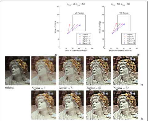
Figure 9a, b represents the statistics point evolution as parameter Sigma increasing from 2 to 32 with fixed parameters (mmin,mmax) = (50, 250) and (mmin,mmax) = (100, 120), respectively. Figure 9c, d shows the resulting images of the experiment in Figure 9a, b, respectively. In Figure 9a, b, we can see that the parameter Sigma significantly influences the image contrast after enhance-ment processing. A smaller (larger) value of Sigma leads to a smaller (larger) value of overall contrast; hence, the parameter Sigma is useful to control the overall contrast of the enhanced output.
Summarizing the parameter tweaking experiment, we have the following observations.
(1) In the proposed method, the parametersmminand
mmax control the overall lightness of the enhanced
output.
(2) In contrast to observation (1), the parameter Sigma controls the overall contrast of the enhanced output.
(3) Based on the observations (1) and (2), the pro-posed method thus provides capability to simultaneously and adjustably enhance the overall lightness and con-trast of the enhanced output.
5.2. Quantitative comparison with other methods
In this section, the performance of the proposed algo-rithm was tested by employing 30 test images, which include insufficient lightness and contrast images. The quantitative method presented in [23], which had been used in previous studies [12,15,24], is employed in the experiments to quantitatively evaluate the performance of the proposed method and three state-of-the-art meth-ods: MSR [14], adaptive and integrated neighborhood-dependent approach for nonlinear enhancement (AIN-DANE) [12], and WDRC [18]. Table 1 tabulates the parameter setting for each compared method used in the experiments. For the proposed method, the values of
parameters mmin and mmax are set as 50 and 250,
respectively. The value of parameter Sigma is tweaked from 4 to 16, which empirically generates satisfactory local contrast enhancement results.
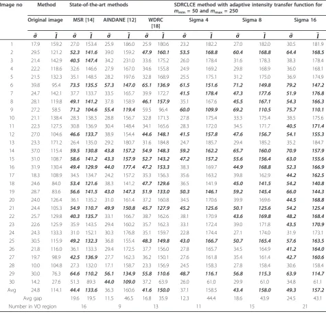
Table 2 records the quantitative measure of the enhanced results obtained by the proposed method together with those from other methods for comparison. In Table 2, the symbols¯Iandσ¯ denote the mean of image and the mean of regional standard deviation, respectively. Furthermore, the values in bolditalic font in Table 2 indi-cate that the quantitative measure falls in the VO region defined in Figure 6. From Table 2, it is clear that the pro-posed SDRCLCE method with Sigma 16 achieves good enhancement on image lightness and local contrast in most of the test images. Moreover, when one compares the average quantitative measure of all 30 test images, the Visually
Optimal
40 80
Mean of Image
Mean of Standard Deviation 100
200
Insufficient Contrast
and Lightness
Insufficient Lightness Insufficient
Contrast
MSR method, WDRC method, and the proposed SDRCLCE method with Sigma 8 and Sigma 16 generate the average quantitative measures satisfying good visual representation condition defined from the VO region. By comparing the gap of average quantitative measure between the original images and the enhanced ones, the improvement of the proposed SDRCLCE method can pro-vide significant enhancement on both image lightness and local contrast when increasing the value of parameter Sigma. This can also be seen from Table 2 that the total number of quantitative measures falling in the VO region for the proposed method is increased when increasing Sigma from 4 to 16. Moreover, the proposed SDRCLCE method with Sigma 16 provides the maximum number of quantitative measures falling in the VO region compared with the other methods. This implies that the proposed
SDRCLCE method not only provides a significantly improvement on the enhanced results, but also possesses the adjustability to control the level of enhancement achieved at the output.
Remark 1
It is difficult to find the global optimal values of the parameters of the proposed method since the visual quality of an image depends not only on the nature of the image, but also on the displaying equipment and user preference. However, the quantitative evaluation method based on the VO region provides a possible way to find the suboptimal settings for the proposed method. Hence, the results shown in Table 2 indicate that the suboptimal values of the parameters of the proposed method could be mmin= 50, mmax= 250, and Sigma = 16 for the employed test images.
(a) (b)
(c)
Original
40
min
4
m
m
min60
6
m
min80
8
m
min100
1
(d)
Remark 2
Although increasing the value of parameter Sigma is able to increase the local contrast enhancement capabil-ity of the proposed method, it may introduce unwanted artifacts, such as image noise and halo effects [6], in the enhanced output. This problem can be resolved by com-bining a Gaussian-pyramid-based adaptive scale selec-tion method [6] or a multi-scale convoluselec-tion method [12] with the proposed method; however, this design usually requires lots of computations and decreases the computational efficiency of the entire enhancement pro-cess. Therefore, if real-time processing is required, such as real-time video enhancement, visual tracking, visual servoing, etc., the proposed method with a fixed and suitable Sigma value provides a high throughput
enhancement process with acceptable results.
Empirically, the value of Sigma can be set from 2 to 16 that provide a satisfactory result with fewer artifacts.
5.3. Visual comparison with other methods
Figures 10a and 11a show the test images no. 29 and 30, respectively. Both images represent with insufficient lightness and contrast as indicated in Table 2. Figure 10b-d is the enhanced results obtained from MSR method, AINDANE method, and WDRC method, respectively. From visual comparison, it is clear that each compared method preserves the contrast between different regions of the image to produce a significant improvement on the visual appearance. However, these methods may not enhance the fine details in dark area surrounded by bright area in the resulting images, such as the words on the signboard in Figure 10, due to
(a) (b)
(c)
Original
150
max
1
m
m
max190
1
m
max210
2
m
max250
2
(d)
preserving the difference between regional brightness in different regions of the image.
In contrast, the proposed method may deteriorate visual appearance of the enhanced images since the resulting images of the proposed method have a com-pressed dynamic range with high local contrast that might cause an unnatural image appearance. However, the proposed method performs better in fine details restoration in dark regions and local contrast
enhancement in bright regions of the image. Figure 10e shows the enhancement result obtained from the pro-posed adaptive intensity transfer function (11) with Sigma 16. In Figure 10e, it is clear that the proposed intensity transfer function restores the fine details in dark regions but decreases the local contrast in bright regions in the resulting image. Figure 10f illustrates the enhanced results obtained by the proposed SDRCLCE method (17) with a = 1 (local contrast preservation)
(a) (b)
(c)
Original Sigma 22 Sigma 88 Sigma 161 Sigma 323
(d)
Fi 9
Figure 9Experiment results of tweakingSigmafrom 2 to 32 with (a) fixedmmin= 50 andmmax= 250; (b) fixedmmin= 100 andmmax = 120; (c) resulting images of experiment (a); (d) Resulting images of experiment (b).
Table 1 Parameter setting for each compared method used in the experiments
Compared method Parameter setting
MSR [14] N= 3,c1= 15,c2= 80,c3= 250,G= 200,b= 135,wn= 1/3
AINDANE [12] Single scale with Sigma = 64
WDRC [18] Fourth-order Daubechies wavelet,d= 2.0 for contrast enhancement
and Sigma 16. It can be seen in Figure 10f that the pro-posed SDRCLCE method simultaneously restores the fine details in dark regions and preserves the local con-trast in bright regions in the resulting image. Further-more, Figure 10g-i is the enhanced results obtained by the proposed method (17) with a = -1 (local contrast enhancement) and Sigma 4, Sigma 8, and Sigma 16, respectively. The resulting images show that the overall fine details and local contrast of the image are enhanced accordingly as the value of Sigma increases. Therefore, the proposed SDRCLCE method is able to produce a significant improvement on the visual quality of LDR
images, which can also be seen from Figure 11. In Fig-ure 11, each compared method produces unnatural image appearance, which is caused by over-enhancing the dark regions while preserving the regional brightness difference between dark and bright areas in the image. On the other hand, the proposed SDRCLCE algorithm with the adaptive intensity transfer function produces a satisfactory enhancement result that not only restores the fine details, but also enhances the local contrast of the object with fewer artifacts. Therefore, these experi-mental results validate that the proposed method satis-factorily enhances the visual quality of LDR images in
Table 2 Quantitative measure of enhanced images
Image no Method State-of-the-art methods SDRCLCE method with adaptive intensity transfer function for
mmin= 50 andmmax= 250 Original image MSR [14] AINDANE [12] WDRC
[18]
Sigma 4 Sigma 8 Sigma 16
¯
σ ¯I σ¯ I¯ σ¯ ¯I σ¯ ¯I σ¯ ¯I σ¯ ¯I σ¯ ¯I
1 17.9 159.2 27.0 153.4 25.9 186.0 25.9 180.6 23.2 182.2 27.0 182.0 30.5 181.9
2 29.5 121.2 52.3 141.6 39.0 159.2 47.9 160.1 53.5 168.8 60.4 168.8 64.4 168.5
3 21.4 142.9 40.5 147.4 34.2 231.0 33.6 175.2 26.0 178.4 31.6 178.3 38.3 178.4
4 22.2 118.6 32.6 146.6 27.9 167.0 34.6 155.8 24.9 169.2 29.8 168.9 36.0 168.1
5 21.5 132.3 35.1 148.5 28.2 197.6 32.8 168.9 25.5 175.1 31.2 175.0 36.9 174.9
6 39.8 95.4 73.5 135.5 57.3 147.0 65.1 136.9 61.5 151.6 71.2 149.8 79.2 147.2
7 24.7 142.1 37.7 133.7 33.5 165.7 39.9 172.7 41.5 178.4 47.3 177.6 51.9 176.8
8 28.1 119.8 49.1 141.2 37.8 158.9 46.1 157.9 35.1 167.6 45.5 167.1 54.3 166.3
9 27.2 58.5 71.2 104.6 55.4 119.4 59.5 96.4 60.0 109.9 69.2 110.5 75.7 110.1
10 21.1 138.4 28.3 138.3 28.8 156.7 32.8 171.3 27.8 175.4 33.3 175.4 38.5 175.6
11 22.3 127.5 30.8 136.9 30.4 148.4 34.1 165.6 28.3 172.0 34.5 171.7 40.5 171.4
12 27.0 104.6 46.6 133.7 38.9 154.4 44.6 148.1 41.5 157.8 47.6 156.7 54.1 155.3
13 23.3 171.2 26.4 135.0 29.2 180.7 31.6 184.8 24.7 185.7 29.4 185.2 35.2 184.7
14 37.0 115.4 59.5 130.8 43.8 157.2 54.9 148.3 59.2 162.2 65.7 160.0 70.9 157.9
15 31.0 108.7 58.6 141.2 43.3 157.9 52.7 143.2 47.2 157.2 55.6 156.4 63.0 155.6
16 31.9 130.4 49.4 129.9 44.0 177.4 47.2 153.3 38.3 169.7 44.9 168.8 52.3 166.9
17 18.3 108.9 34.5 134.7 24.2 157.2 35.3 156.3 35.6 163.2 39.8 162.9 44.2 162.5
18 24.6 84.0 53.4 121.6 38.3 141.2 47.7 129.6 36.5 141.9 45.0 141.5 54.2 140.8 19 28.7 83.6 56.6 141.5 43.0 147.3 51.9 133.0 50.3 146.1 59.2 145.4 66.0 144.3
20 24.0 126.4 36.1 135.2 31.0 161.4 37.2 160.8 34.5 170.6 39.9 169.6 44.5 168.8
21 24.4 105.3 54.9 110.7 49.9 150.8 45.7 127.9 45.2 125.6 50.1 125.6 54.2 125.4
22 25.7 129.8 40.3 135.7 33.1 166.7 38.7 162.6 38.1 170.9 43.6 169.8 48.2 168.4
23 22.6 125.9 35.9 143.5 29.4 160.2 35.7 162.3 33.1 172.4 39.0 171.8 43.5 170.9
24 24.3 133.3 31.0 152.1 30.3 176.8 35.1 159.7 22.8 174.4 27.1 174.0 31.9 173.1
25 30.5 115.9 49.2 132.3 36.8 155.4 48.3 149.8 43.0 166.7 50.7 165.4 57.6 163.5
26 21.8 116.0 36.1 133.3 29.4 172.5 37.7 156.0 27.8 165.7 34.5 164.9 41.2 164.0
27 19.7 98.9 42.5 136.9 27.7 162.3 36.2 150.1 27.6 161.8 35.4 161.4 42.7 160.6
28 10.0 104.8 27.3 132.0 17.1 158.7 23.3 156.9 24.5 158.3 27.8 158.4 30.6 158.4
29 30.0 76.3 64.6 110.2 56.1 134.9 55.8 110.6 48.7 116.1 56.8 115.3 63.9 114.7 30 14.2 27.6 51.3 89.3 44.0 109.0 37.2 63.9 26.0 61.0 29.9 61.0 34.8 61.1 Avg 24.8 114.1 44.4 133.6 36.3 160.6 41.6 150.0 37.1 158.5 43.4 158.0 49.3 157.2
Avg gap 19.6 19.5 11.5 46.5 16.8 35.9 12.3 44.4 18.6 43.9 24.5 43.1
Number in VO region 16 9 13 11 15 21
terms of dynamic range compression and local contrast enhancement as we expected.
Figure 12 shows the resulting images obtained from the proposed method with linear RGB and YCbCrcolor remapping approaches presented in Section 4. Figure
12a illustrates the test image no. 9, which also repre-sents with insufficient lightness and contrast as indi-cated in Table 2. Figure 12b presents the resulting image obtained from the proposed method with linear RGB color remapping. In order to evaluate the
(a) (b) (c)
(d) (e) (f)
(g) (h) (i)
performance of the proposed linear YCbCrcolor remap-ping method, the original image is first transformed into YCbCrcolor space, and the proposed SDRCLCE method is then applied to the Y component only. Figure 12c shows the result obtained by only enhancing Y compo-nent while preserving Cb, Cr components. It can be observed in Figure 12c that resulting image represents with less saturated colors because of leaving chromi-nance components unchanged. To overcome this
pro-blem, the proposed linear YCbCr color remapping
method is applied to the enhanced YCbCr color image, and Figure 12d shows the resulting image after trans-forming from YCbCr into RGB color space. As can be seen by visually comparing Figure 12d with b, the result-ing images of the proposed method with linear YCbCr color remapping approach are similar to, but not the same as, the results obtained with linear RGB color remapping. This problem is caused by that it is
suggested to use HSV intensity value in the RGB color image enhancement to achieve color consistency [25]; however, the enhancement process in YCbCrcolor space is difficult to obtain the HSV intensity value since YCbCr color image uses NTSC intensity value as the luminance component based on NTSC standard. There-fore, the proposed YCbCr color remapping approach is helpful to speed up the process of video signal enhance-ment, but it may result inconsistent colors, like the blue colors in Figure 12, in the enhanced image.
Remark 3
Color constancy is an important issue in the topic of color image enhancement. In the current design, the proposed method cannot handle color constancy pro-blem and fails to produce color constant results for the images with color cast or color shift. However, this pro-blem can be resolved by combining a color restoration algorithm, such as white-patch algorithm [26] or color
(a) (b) (c)
(d) (e) (f)
(g) (h) (i)
correction algorithm [27], with the proposed method to remove color cast from the enhanced results. In this article, we do not cover the color restoration problem and only focus the topic on dynamic range compression with local contrast enhancement problem.
5.4. Computational speed
The proposed method had been implemented in C++ in Windows XP environment on a PC with Intel Core 2 processor, which is running at 2.4 GHz with 2GB of memory. In our implementation, a fast Gaussian filter
was employed to improve the computing performance for the proposed method. Moreover, the process of the proposed SDRCLCE method was implemented using parallel programming with OpenMP to improve the computational efficiency. The processing time required for the proposed method is compared with AINDANE and MSR methods, which are also imple-mented in C++. Furthermore, the process of MSR method was accelerated by using Intel OpenCV library. Table 3 tabulates the processing time required for each method to process images with various sizes.
(a) (b)
(c) (d)
Figure 12Validation of the proposed linear YCbCrcolor remapping method.(a)Original picture; enhanced by the proposed method with (b)linear RGB color remapping,(c)only enhancing Y component while preserving Cb, Crcomponents, and(d)linear YCbCrcolor remapping.
Table 3 Processing time comparison for RGB image enhancement
RGB image size (pixel) State-of-the-art methods Processing time by SDRCLCE method
Processing time by MSR (ms) Processing time by AINDANE (ms) Sigma 4 (ms) Sigma 8 (ms) Sigma 16 (ms)
320 × 240 49.4829 158.0348 4.9578 6.3952 9.0608
640 × 480 184.8582 348.5715 20.8365 26.2822 35.4939
From Table 3, it is obviously that the parallelized SDRCLCE method requires less processing time, fol-lowed by OpenCV accelerated MSR method and
sin-gle-scale AINDANE method. The process of
AINDANE method is difficult to parallelize efficiently since it was developed based on a sequential process framework. Although the process of MSR method could also be parallelized, it requires processing all three color bands and performs weighted sum of sev-eral different scale outputs in the logarithmic domain, which is done with floating point operations and thus decreases the computational efficiency. From the experimental results, the processing time of SDRCLCE method takes less than 40 ms in average for a full color image with size 640 × 480 pixels that is suitable for many real-time applications.
6. Conclusion and future work
This article proposed a novel image enhancement
algorithm which simultaneously accomplishes
dynamic range compression and local contrast enhancement. One merit of the proposed method is that the proposed SDRCLCE algorithm can combine with any monotonically increasing and continuously differentiable intensity transfer function, such as the typical gamma curve, to achieve dynamic range com-pression with local contrast preservation/enhance-ment for LDR images. Moreover, a novel intensity transfer function is proposed to adaptively control the curvature of the processed intensity mapping curve for each pixel depending on the local mean value. By combining the proposed intensity transfer function with SDRCLCE algorithm, the proposed method pos-sesses the adjustability to separately control the level of enhancement on the overall lightness and contrast achieved at the output. The proposed method is also extended to combine with a linear RGB/YCbCr color remapping algorithm that preserves color information of the original image during image/video enhance-ment process. Therefore, the proposed method pro-vides a useful lightness-contrast enhancement solution for the applications of image/video proces-sing because of the flexible adjustability with image color preserving. The performance of the proposed SDRCLCE method has been compared with three state-of-the-art methods, both quantitatively and visually. Experimental results show that the proposed SDRCLCE method not only outperforms all of them in terms of dynamic range compression and local contrast enhancement, but also provides good visual representation in visual comparison. Moreover, the proposed method is amenable to parallel processing, which improves the processing speed of SDRCLCE method to satisfy the requirement of real-time
applications. The combination with a color restora-tion algorithm is left to our future study.
Appendix
This appendix presents the derivation of Equation 5 from (4). Let Ωxy denote a neighborhood of specified
size, centered at (x,y). The value of output local average luminance of the pixels inΩxy can be calculated by the
expression
gavg(x,y) =
(i,j)∈xy
wi,jyT(x+i,y+j), (A1)
wherewi,j for (i, j) Î Ωxy are the weights satisfying
(i,j)∈xy
wi,j= 1. Substituting (4) into (A1), we have
gavg(x,y) =
(i,j)∈xy
wi,jT[Iin(x+i,y+j)], (A2)
where the term T[Iin(x+i, y+j)] can be approximated by a first-order Taylor series expansion such that
T[Iin(x+i,y+j)]∼=T[Iin(x,y)] +
dT(X)
dX
X=Iin(x,y)
×Iin(x+i,y+j)−Iin(x,y)
.(A3)
Substituting (A3) into (A2) yields
gavg(x,y)∼=T[Iin(x,y)] +
dT(X) dX
X=Iin(x,y)×
⎡
⎣
(i,j)∈xy
wi,jIin(x+i,y+j)−Iin(x,y)
⎤ ⎦,(A4)
where
(i,j)∈Sxy
wi,jIin(x+i,y+j) =Iavg(x,y), and thus
the derivation of (5) is completed.
Acknowledgements
This study was supported by the National Science Council of Taiwan, ROC, under the grant nos. NSC 99-2218-E-032-004 and NSC 100-2221-E-032-011.
Competing interests
The authors declare that they have no competing interests.
Received: 1 March 2011 Accepted: 13 September 2011 Published: 13 September 2011
References
1. Seow M-J, Asari VK:Color characterization and balancing by a nonlinear line attractor network for image enhancement.Neural Process Lett2005, 22(3):291-309.
2. Wang C, Sun L-F, Yang B, Liu Y-M, Yang S-Q:Video enhancement using adaptive spatio-temporal connective filter and piecewise mapping.
EURASIP J Adv Signal Process2008,2008(165792):13.
3. Bertalmío M, Caselles V, Provenzi E, Rizzi A:Perceptual color correction through variational techniques.IEEE Trans Image Process2007, 16(4):1058-1072.
4. Palma-Amestoy R, Provenzi E, Bertalmío M, Caselles V:A perceptually inspired variational framework for color enhancement.IEEE Trans Pattern Anal Mach Intell2009,31(3):458-474.
5. Radiance homepage. [Online].[http://radsite.lbl.gov/radiance/].
6. Reinhard E, Stark M, Shirley P, Ferwerda J:Photographic tone reproduction for digital images.Proc SIGGRAPH2002ACM; 2002, 267-277.
8. Horiuchi T, Tominaga S:HDR image quality enhancement based on spatially variant retinal response.EURASIP J Image Video Process2010, 2010(438958):11.
9. Bennett EP, McMillan L:Video enhancement using per-pixel virtual exposures.ACM Trans Graph2005,24(3):845-852.
10. Stark JA:Adaptive image contrast enhancement using generalizations of histogram equalization.IEEE Trans Image Process2000,9(5):889-896. 11. Reza MAli:Realization of the contrast limited adaptive histogram
equalization (CLAHE) for real-time image enhancement.J VLSI Signal Process2004,38(1):35-44.
12. Tao L, Asari VK:Adaptive and integrated neighborhood-dependent approach for nonlinear enhancement of color images.J Electron Imag 2005,14(4):043006-1-043006-14.
13. Tao L, Seow M-J, Asari KVijayan:Nonlinear image enhancement to improve face detection in complex lighting environment.Int J Comput Intell Res2006,2(4):327-336.
14. Jobson D, Rahman Z, Woodell G:A multiscale Retinex for bridging the gap between color images and human observation of scenes.IEEE Trans Image Process1997,6(7):965-976.
15. Choudhury A, Medioni G:Perceptually motivated automatic color contrast enhancement.IEEE International Conference on Computer Vision and Workshops, California, Los Angeles, CA2009, 1893-1900.
16. Land E:Recent advances in Retinex theory.Vis Res1986,26(1):7-21. 17. Monobe Y, Yamashita H, Kurosawa T, Kotera H:Dynamic range
compression preserving local image contrast for digital video camera.
IEEE Trans Consum. Electron2005,51(1):1-10.
18. Unaldi N, Asari KV, Rahman Z:Fast and robust wavelet-based dynamic range compression with local contrast enhancement.Proc of SPIE, Orlando, FL2008,6978:697805-1-697805-12.
19. Unaldi N, Asari KV, Rahman Z:Fast and robust wavelet-based dynamic range compression and contrast enhancement model with color restoration.Proc of SPIE, Orlando, FL2009,7341:7341111-73411112. 20. Peli E:Contrast in complex images.J Opt Soc Am A: Opt Image Sci Vis
1990,7(10):2032-2040.
21. Polesel A, Ramponi G, Mathews VJ:Image enhancement via adaptive unsharp masking.IEEE Trans Image Process2000,9(3):505-510.
22. International Telecommunications Union, ITU-R BT.601. [Online].[http:// www.itu.int/rec/R-REC-BT.601/].
23. Jobson JDaniel, Rahman Zia-ur, Woodell AGlenn:The statistics of visual representation.Vis Inf Process XI, Proc SPIE2002,4736:25-35.
24. Choudhury A, Medioni G:Perceptually motivated automatic color contrast enhancement based on color constancy estimation.EURASIP J Image Video Process2010,2010(837237):22.
25. Tao L, Tompkins R, Asari KVijayan:An illuminance-reflectance model for nonlinear enhancement of color images.Proceedings of IEEE Computer Society Conference on Computer Vision and Pattern Recognition, San Diego, CA2005, 159-166.
26. Land EH:The Retinex theory of color vision.Sci Am1977,237(6):108-128. 27. Rizzi A, Gatta C, Marini D:A new algorithm for unsupervised global and
local color correction.Pattern Recogn Lett2003,24:1663-1677.
doi:10.1186/1687-5281-2011-6
Cite this article as:Tsai and Chou:A novel simultaneous dynamic range compression and local contrast enhancement algorithm for digital video cameras.EURASIP Journal on Image and Video Processing2011
2011:6.
Submit your manuscript to a
journal and benefi t from:
7Convenient online submission 7Rigorous peer review
7Immediate publication on acceptance 7Open access: articles freely available online 7High visibility within the fi eld
7Retaining the copyright to your article