www.mech-sci.net/7/107/2016/ doi:10.5194/ms-7-107-2016
© Author(s) 2016. CC Attribution 3.0 License.
Solving the double-banana rigidity problem:
a loop-based approach
Florian Simroth1, Huafeng Ding2, and Andrés Kecskeméthy1 1University of Duisburg-Essen, Duisburg, Germany 2China University of Geosciences Wuhan, Wuhan, China
Correspondence to: Florian Simroth ([email protected])
Received: 6 October 2015 – Revised: 20 January 2016 – Accepted: 6 March 2016 – Published: 8 April 2016
Abstract. Rigidity detection is an important tool for structural synthesis of mechanisms, as it helps to unveil possible sources of inconsistency in Grübler’s count of degrees of freedom (DOFs) and thus to generate con-sistent kinematical models of complex mechanisms. One case that has puzzled researchers over many decades is the famous “double-banana” problem, which is a representative counter-example of Laman’s rigidity condi-tion formula for which existing standard DOF counting formulas fail. The reason for this is the body-by-body and joint-by-joint decomposition of the interconnection structure in classical algorithms, which does not unveil structural isotropy groups for example when whole substructures rotate about an “implied hinge” according to Streinu. In this paper, a completely new approach for rigidity detection for cases as the “double-banana” coun-terexample in which bars are connected by spherical joints is presented. The novelty of the approach consists in regarding the structure not as a set of joint-connected bodies but as a set of interconnected loops. By tracking isolated DOFs such as those arising between pairs of spherical joints, rigidity/mobility subspaces can be easily identified and thus the “double-banana” paradox can be resolved. Although the paper focuses on the solution of the double-banana mechanism as a special case of paradox bar-and-joint frameworks, the procedure is valid for general body-and-joint mechanisms, as is shown by the decomposition of spherical joints into a series of revolute joints and their rigid-link interconnections.
1 Introduction
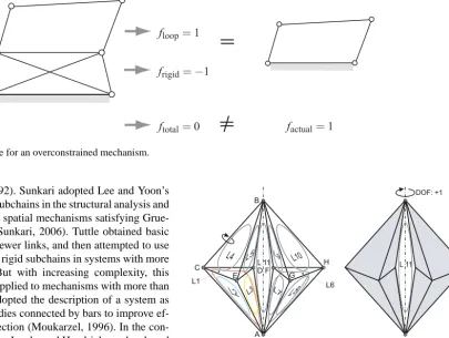
Rigidity detection has attracted researchers in the field of robotics and mechanisms since many decades, as it is a necessary component in the creative automatic synthesis of mechanisms (Ding et al., 2012), the processing of CAD-generated models (Lee, 2008; Moinet et al., 2014), the anal-ysis of flexibility and dynamics of proteins (Jacobs et al., 2002), and others. The problem is (1) to identify whether a mechanism contains substructures with negative DOF (so-called “degenerate chains”), and if so, (2) to detect the parts forming those (over-) rigid substructures, such that their neg-ative DOF do not illicitly cancel out positive DOF in other parts of the structure (Fig. 1).
Based on Laman’s theorem (Laman, 1970), many algo-rithms were proposed to detect the rigidity for both planar and simple spatial mechanisms. Tay addressed the detection of rigidity for rigid bodies connected by bars represented
nonpla-ftotal= 0 factual= 1
frigid= −1
floop= 1
Figure 1.Simple example for an overconstrained mechanism.
nar (Lee and Yoon, 1992). Sunkari adopted Lee and Yoon’s method to detect rigid subchains in the structural analysis and synthesis of planar and spatial mechanisms satisfying Grue-bler’s DOF equation (Sunkari, 2006). Tuttle obtained basic rigid chains with 7 or fewer links, and then attempted to use these chains to identify rigid subchains in systems with more links (Tuttle, 1996). But with increasing complexity, this method can hardly be applied to mechanisms with more than 10 links. Moukarzel adopted the description of a system as a collection of rigid bodies connected by bars to improve ef-ficiency of rigidity detection (Moukarzel, 1996). In the con-text of material sciences, Jacobs and Hendrickson developed a graph-based algorithm for detecting overconstrained re-gions and rigid clusters of two-dimensional networks (Jacobs and Hendrickson, 1997). Another method used for structural analysis is the ear decomposition which originates from the work of Robbins and Whitney (Robbins, 1939; Whitney, 1932) for which a mechanism is decomposed by sequentially removing a sequence of “ears”, i.e. serial chains with inter-nal binary bodies connected at their endpoints to bodies of at least degree two, from the graph. Franzblau generalized this approach to chains including cycles and bridges, and by successively analyzing the subsystems using theorems based on the rigidity matrix, he was able to determine the mini-mal and maximini-mal boundaries for the degrees of freedom for a given bar-and-joint framework (Franzblau, 1999, 2000), however without providing an explicit DOF count formula. A further approach is the use of matroids for determining globally rigid substructures (Servatius and Servatius, 2010). This method is very powerful for planar systems but has not been fully extended yet to spatial mechanisms. Moreover, the methodology is based on bar-frameworks whose general-ization to kinematical joints is still a pending problem. Lee, Streinu and Theran as well as Chubynsky and Thorpe used combinatorial approaches like the pebble game algorithm to analyze rigidity (Lee et al., 2005, 2008; Chubynsky and Thorpe, 2007; Streinu and Theran, 2008). Shai, Servatius, Sljoka, Whiteley, and Müller focused on the decomposition of mechanisms into Assur components for mobility analysis (Servatius et al., 2010; Sljoka et al., 2011; Shai et al., 2013; Shai and Müller, 2013). Michelucci and Foufou proposed the
DOF: +1
DOF: -1 A
B
C D
E F G
H
L1
L2 L3
L4 L5 L 11
L6
L8
L7L10
L9
L 11
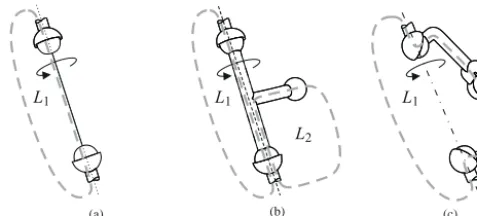
Figure 2.The “double-banana” mechanism.
(a) Recursively solvable system (b) Non-recursively solvable system
L1 L2
L3 L4
A B C
β11 β12
β13
β21
β24
β41
β31
β32
L1
L2 L3 L4
L5
A
B C D
L1 L2
L3
L4
A
B
C β11 β12
β13
β21 β24 β41
β31
β32
L1
L2 L3 L4
L5
A
B
C D
L1 L2
L3
L4
A
B
C β11 β12
β13
β21 β41
β31
β32
L1
L2 L3 L4
L5
A
B
C D
q
˜
q
Figure 3.Mapping of mechanisms to kinematical networks.
2 The “double-banana” case
Although many rigidity detection algorithms have been pro-vided to date, an automatic finite-mobility rigidity detec-tion algorithm for systems involving “implied hinges” (see below) such as the famous “double-banana” case shown in Fig. 2, to the knowledge of the authors has not been reported so far. The “double-banana” consists of 18 bars connected at 8 nodes which can be interpreted as (multiple) spheri-cal joints. If we give each node 3 DOFs and subtract one constraint per bar, then the Grübler count gives DOF =0, thus suggesting that the structure is rigid. However, one can clearly “see” in Fig. 2 that the “double-banana” structure consists of two rigid bipyramids, one at the left and one at the right, which are coupled together by two spherical joints (A and B). Thus, the segmentABis an “implied hinge” (Cheng et al., 2009) about which the two halves can rotate with re-spect to each other, while the longitudinal direction along this edge is over-constrained with DOF= −1. This implied
DOF remains also undetected by the famous test equation for rigidity according to Maxwell’s rule proposed in (Maxwell, 1864), which states that a statically and kinematically deter-mined framework with b bars and j joints follows the equa-tion
b=3j−6. (1)
struc-ture with the “double-banana” as an example (Cheng et al., 2009), and Rojas proposed the “double-banana” closure con-ditions as a paradigm for position analysis in robots (Rojas and Thomas, 2013). The cause for the “double-banana” para-dox is that there exist “isolated” DOFs in the mechanism (e.g. the bar spin between two spherical joints) which create an own level of transmission kinematics, and which thus need to be tracked in order to be able to detect which substructures are rigid and which are movable. We propose in this paper a novel procedure for tracking such isolated DOFs by us-ing an alternative method for describus-ing kinematical interde-pendencies, called the “kinematical network” (Kecskeméthy, 1993), in which the mechanism is regarded not as a sys-tem of connected bodies, but as a syssys-tem of interconnected kinematical loops. A kinematical loop can be regarded as a closed chain of bodies which corresponds to an elementary cycle in a graph theoretical sense. If the underlying graph of the mechanism is not at least 2-edge-connected, i.e. it con-tains bridges or is separated, the graph first is dissected into its 2-edge-connected components, called clusters, for which the loop decomposition algorithm is applied separately. Of course, rigidity needs to be detected only within each clus-ter, as non-connected or 1-edge-connected clusters can never reduce the DOF in comparison with the sum of their inter-nal DOFs. In the following, the method of “kinematical net-work” is briefly reviewed here for better understanding of the present paper, and then our novel rigidity-detection proce-dure for “double-banana” types of mechanisms is elucidated.
3 Description of mechanisms as kinematical
networks
The concept of mechanism description using a network of linearly connected loops was introduced in (Kecskeméthy, 1993), and a fully automatic implementation in the symbolic formula manipulation software Mathematica for general pla-nar, spherical, translational and spatial cases is described in (Kecskeméthy et al., 1997). The following planar examples are used for illustration of the method, but the concepts apply one-to-one also to spatial cases.
In this approach, as a first step, a minimal cycle basis com-prising a set of smallest independent loopsLi of the mecha-nism is determined, where “length” is measured in terms of the number of involved joint variables. According to the Eu-ler cyclomatic number, the numbernLof independent loops is given by
nL=nG−nB+1, (2)
where nB is the number of bodies including the ground frame, andnGis the number of binary joint connections. For example, for Fig. 3a one hasnB=10 andnG=13 and thus nL=4, while for Fig. 3b it holdsnB=12 andnG=16, and thusnL=5. Each loop is first regarded independently of the others, and its local degree of freedom fLi is determined,
which is the number of loop joint coordinates minus the di-mension of the subgroup of Euclidean motion in which the bodies of the loop locally move (spatial, planar, spherical, translational, etc.).
As the next step, the coupling conditions between the loops are determined. These arise exactly at those joints in which the number of incident loops is equal to or larger than the number of incident bodies and correspond to a balance of inner joint coordinates of the incident loops and some con-stants. More precisely, if a jointGi connectsnB(Gi) bodies, then the bodies at the jointGican move with[nB(Gi)−1 ]·k relative degrees of freedom with respect to each other, where kis the dimensionality of the jointGi, e.g.k=1 for a revo-lute joint ork=3 for a spherical joint. Thus ifnL(Gi) loops are incident at jointGi, the relative joint variables introduced independently of each other in each loop at that joint must fulfill
nC(Gi)=[nL(Gi)−nB(Gi)+1 ]·k (3)
balance equations, which therefore yields uniquely the num-ber of coupling conditions at that joint (Kecskeméthy, 1993). For example, in joint A of Fig. 3a, there are two incident loops and two incident bodies, yielding one coupling equa-tion. This corresponds to the condition that the sum of joint coordinates β12 and β21 plus a constant is equal to 360◦, yielding a linear coupling between the loopsL1andL2. Note that fornC> k, while the number of coupling conditions is unique, the choice of the balance conditions is non-unique, as any set of combinations of admissible balance conditions gives again a suitable balance condition.
The thus connected loops form the so-called “undirected kinematical network” in which the loops represent local non-linear transmission elements and the couplings between the loops represent the global interrelationships. From the kine-matical network, the DOF can be obtained as the sum of local DOFs of all loops minus the sum of loop coupling conditions. In Fig. 3a, there are four four-bar loops with local DOF=1 each, and three loop coupling conditions. Thus the overall DOF is 1. In Fig. 3b, there are five four-bar loops with lo-cal DOF=1 each, and four loop coupling conditions, thus the global DOF is again 1. This shows that the DOF count-ing over the loops and their couplcount-ings is fully equivalent to the usual Grübler count, giving a new and consistent type of Grübler DOF formula. Note however that here, in contrast to the classical Grübler count, one can easily combine planar, spherical, and spatial loops.
iteratively. An advantage of the kinematical network is that one can easily recognize recursively solvable substructures by the so-called sink method (Kecskeméthy, 1993): here, one searches iteratively for elements in the kinematical network for which the number of edges is less than or equal to the local degree of freedom of the element. After finding such an element, all edges are oriented into the element, the element together with all ingoing edges is removed, and the procedure is re-applied to the rest of the system. If the procedure cov-ers all loops, one obtains a recursive solution flow, i.e. each loop can be solved as a function of a “true” external input and/or outputs of previously solved loops (example: Fig. 3a). If this is not the case, the network must be solved iteratively by choosing additional “pseudo” inputs and following the so-lution flow until an element is overconstrained, which yields the implicit constraint equation needed to be solved by an it-erative root finding algorithm such as Newton’s method (ex-ample: Fig. 3b) where a pseudo inputeq has been applied to loopL2 and the implicit constraint equation results in loop coupling condition “C”).
4 Types of isolated degrees of freedom
Isolated degrees of freedom are mobilities that leave some characteristic relative measurements between surrounding substructures locally invariant. In literature, several kinds of names and concepts are used in this respect. The different concepts and terminology might lead to confusion so that a short introduction is given.
Hunt introduced “superfluous spin-freedoms” which arise for the rotation of a bar in-between two spherical joints, which he suggests to remove for kinematic analysis (Hunt, 1978). Waldron uses the term “passive degree of freedom” for the same type of motion (Waldron, 1973). However, this term might lead to confusion as in parallel kinematics ma-chines it refers to non-actuated chains (legs) for which the joint variables are dependent functions of actuated ones (Liu et al., 2014). This is also the meaning used in robotics by (Bennett and Hollerbach, 1991) when the joint variables of a virtual contact joint are a function of the actuated robot degrees of freedom. Also, in control theory, the term pas-sive DOF refers to non-controlled degrees of freedom which however are properly transmitted throughout the mechanism (Shiriaev et al., 2010). For example, one four-bar mechanism could have one actuated DOF, while a second four-bar mech-anism on top of it could be non-actuated (passive), thus the control of the first four-bar mechanism is sought which con-trols both stably. Furthermore, the term passive degree of freedom is sometimes used for underactuated manipulators and are accounted for structural flexibilities (Jain and Ro-driguez, 1993; Casals and Amat, 1996). Another term one encounters in this setting is “redundant DOF” (Zhang et al., 2003), which however may lead to confusion as the term re-dundant DOF is used in robotics for robots featuring a greater
(a) (b) (c)
L1 L1 L1
L2
Figure 4.Different types of isolated DOFs: (a) “Fully isolated”, (b) “transmitted isolated”, (c) “structurally isolated”.
number of actuators than necessary for a given task space which allows for special control movements (such as the hu-man arm having seven relative joint motions for six DOFs at the hand). In some cases the term “parasitic DOF” is used for isolated DOFs (Rolland, 1999); however, the term “par-asitic motion” (Carretero et al., 2000) or “par“par-asitic DOF” is also (and more frequently) used to describe unwanted depen-dent motions in some direction such as the vertical axis of a lower mobility platform (Hsu et al., 2004; Isaksson et al., 2015; Merlet, 2005). As a further variant one finds the term parasitic degrees of freedom meaning additional degrees of freedom added to the principal DOFs by compliant joints (Togashi et al., 2014). Finally, in some cases the term “idle DOF” is used in this context (Razmara et al., 2000); how-ever, the term “idle” would imply that the related motion of the isolated DOF is not changing, which is not the case in the present discussion.
In view of the plurality of notions and terms used in dif-ferent contexts, we propose here to use the term “isolated” which most accurately describes the notion of degrees of freedom which have no influence on certain relative quan-tities at the ends of a serial chain, i.e. remain non-transmitted in a certain neighborhood of this chain, but may be transmit-ted to surrounding substructures. This is in close correspon-dence to the original term “superfluous spin-freedom” used by Hunt, and helps to convey the idea that the isolated DOFs might not be “superfluous” or pure “spinning” (meaning that they might be transmitted to overlayed structures or that there is a material axis of rotation). It might be noted that this term has been used in the past in the modeling of active meshes for grasping devices (Mazzone et al., 2003).
In order to track isolated DOFs, three types can be distin-guished according to their scope of action (Fig. 4):
Lj
Li
Lk
ζ
ψ
ξ
α
φ
β
η
θ
γ
Bar 1
2 r
aB
Bar 3
Figure 5.Loop coupling conditions at a multiple spherical joint.
(b) “Transmitted isolated DOF”: these are isolated DOFs which have already been counted once as “fully iso-lated” in one loop, so that they become transmitted in a neighboring loop; an example is shown in Fig. 4b, where the spin of the rod has been counted as isolated in loopL1, but becomes transmitted to loopL2; this will be essential when regarding the transmission of isolated DOFs at loop coupling conditions of spherical joints. Transmitted isolated DOFs will be displayed below in the loop connection graphs as dashed lines.
(c) “Structurally isolated DOF”: these are isolated DOFs that comprise whole substructures; they leave the inter-nal motion of whole subchains within one loop invari-ant but operate on the absolute motion of the chain as proper DOFs; an example is shown in Fig. 4c, where the isolated DOF does not change the internal config-uration of the revolute joint on the spun subchain, but the chain rotates as a whole about the implied spin axis connecting both spherical joints. Note that in this type of isolated DOFs the spin axis is not constant with respect to any body, but changes with the internal motion of the involved subchain. Structurally isolated DOFs will be displayed below in the loop connection graphs as dot-dashed lines.
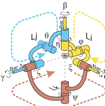
5 Loop coupling conditions at a spherical joint
When multiple loops coincide at one spherical joint, the product of rotation matrices of the relative rotations over all incident loops must yield unity, thus producing 3 indepen-dent coupling conditions. Furthermore, when multiple bars coincide in a spherical joint, one can always decompose the relative rotation between the bars within a loop into two ter-minal rotations about the connecting bars, and one intermedi-ate rotation about some arbitrary axis, which should however be warranted never to become parallel to one of the bars over
the complete motion. In this way, one obtains loop couplings at a spherical joint between two isolated bar spin DOFs and one proper aperture angle for each loop incident to that joint. An example is given in Fig. 5. Here, the loop coupling equa-tion between the three loopsLi,Lj andLkcan be expressed as
Rk(ξ, ψ, ζ)=Rj(η, θ, γ)·Ri(α, ϕ, β), (4)
where R(. . .) denotes the rotation matrix in terms of (z-x -z) Euler angles in the order of the arguments. The coupling equation can be interpreted such that the three internal rota-tionsξ, ψ,ζ of loopLk result numerically as a (nonlinear) function of the three internal rotationsα, ϕ, β andη, θ, γ of loopsLi andLj, respectively. Topologically, this coupling has particular properties due to the implicitly assumed iso-lated DOFs about the bars that are incident to the spherical joint, which can be described qualitatively without resorting to the explicit resolution of the spatial loop coupling condi-tions in terms of the output anglesξ, ψ,ζ, as discussed next. Assuming that the other bar ends in Fig. 5 (not shown) of the bars are also attached to spherical joints, the bars will be allowed to spin about their longitudinal axes. However, only one rotation per bar can be regarded as truly fully isolated: if a loop “registers” one isolated spin as fully isolated, then for the neighboring loop this rotation becomes transmitted. This is shown by the chosen colors in Fig. 5: assuming that the spin of bars 1 and 2 have been registered as fully isolated in loopLi, these can be regarded as immaterial spinnings of the pins within the sleeves of the joints of bars 1 and 2, denoted by anglesαandβ, respectively; however, the rotation within loopLk about bar 1, denoted byξ, is then not fully isolated anymore, and actually sways the brown chain of loopLk as when unfolding two faces of an origami at the edge folded along the axis of bar 1. Thus the angleξ is a transmitted iso-lated DOF. Similarly, the rotation within loopLjabout bar 2, denoted byη, rotates the blue chain within loopLjabout the axis of bar 2, and is thus again a transmitted isolated DOF. Finally, the rotationγ of the inner pin of the revolute joint along bar 3 can be regarded again as a fully isolated DOF once, which in the case of Fig. 5 has been arbitrarily assigned to loopLj. This makes the rotation about bar 3 within loop Lk, denoted byζ, again a transmitted isolated DOF.
f=3
L2
f=3L4
f=3
L5
f=3
L3
f=3
L1
3 f=6
L11
f=3
L7
f=3L9
f=3
L10
f=3
L8
f=3
L6
33 3
3
3 3
3 3
3 3
3
3 3
3 3
3 3
E D F G
A A
Figure 6.The undirected kinematical network of the “double-banana” mechanism.
f=3
L2
f=3
L4
f=3
L5
f=3
L3
f=3
L1
{
{
3{
f=6L11
{
f=3
L7
f=3
L9
f=3
L10
f=3
L8
f=3
L6
{
{
3
3 3 3
3 3
3 3
3 3
3 3
3
3 3
3 3
E D F G
1x
1x 1x
A A
Fully isolated DOF Transmitted isolated DOF Structurallyisolated DOF
Proper DOF
1x 1x
Figure 7.The directed kinematical network of the “double-banana” mechanism.
constant, which means that loopLk induces an implicit con-straint equation for the transmitted isolated DOF ηof loop Lj. This kind of tracking of transmitted isolated DOFs up to locations of implicit constraint equations will prove use-ful for detecting rigid and movable substructures in multiple spherical-spherical bar mechanisms, as shown below.
6 Kinematical network of the “double-banana”
mechanism
As described in section 3, initially the interconnected kine-matical loops are chosen as a set of “smallest” independent loops, in which the sum of numbers of relative joint vari-ables within each loop over all loops is smallest. While the numbernLof independent loops is unique, the choice of the independent loops can have many solutions (Kecskeméthy, 1993). In the present case, we have nL=11 for which we choose 10 triangles within the two bipyramid halves and the quadrilateral loopL11between them shown in Fig. 2. At the beginning, each loop is regarded as an independent trans-mission element, i.e., all relative motions within a loop are regarded as independent. The loop coupling condition gives
one spherical coupling condition at joints E, G, D and F and two spherical coupling conditions at joint A. Using the cou-pling conditions described in Section 5, one obtains for the “double-banana” example of Fig. 2 the undirected kinemati-cal network shown in Fig. 6.
In the process of orienting the edges of the kinematical network, the following steps arise:
1. Each of the loopsL1,. . . , L10 displays 3 local DOFs, which are the three isolated DOFs about the three bars; likewise, loopL11, which comprises four spher-ical joints, displays 6 local DOFs.
2. At each coupling joint, three coupling equations accord-ing to Eq. (4) are produced. Two of these couplaccord-ing con-ditions go into isolated DOFs, while one propagates into a transmission angle, which is the aperture angle of the intermediate joint of thez-x-zdecomposition.
actu-S
5 7 8 9
1
3 2 1 2 1
1x {6} 1x 10} { 1 1 111 1 1 1 1 1 1
1x 11} {
X1 S
1
3 2
5 7 8 9
1x
1x
1
1 1
1 1
1 1
1 1
{1}
{4} 1x {6} 1x 10} {
111 1 1 1 1
1x 11} {
X1
3 2
3 2
1x
1x
1 2
1 1 1 1 1
{1} {4}
1
1 1 1
(a) (b)
Figure 8.Loop connection graph for the kinematical network of Fig. 7 (a) with and (b) without isolated DOFs.
S
2
1x
1
1
{1} 3
1
S
1
5 9
1
1
1x 11} {
3 7
1 1 1
S
1
2 5
1x
1
1 1
{4} 3
1
X2
(a) (b) (c)
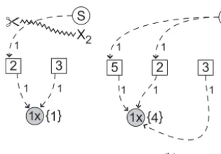
Figure 9.Pruned graphs for each of the four special shared joints.
ally transmits into the loop kinematics and is subject to a constraint condition there due to the triangle condition. Thus, the sink loop actually introduces an implicit equa-tion (marked “1×” in a gray box within the loop) which must be fulfilled by the transmitted DOFs entering the loop. On the other hand, each sink loop features an addi-tional fully isolated DOF, which is about the third edge that is not shared with any other loop. Thus, after ori-enting the edges into the sinks one obtains one implicit equation and one “true” DOF per sink (Fig. 7).
4. After having determined all sinks, the orientation of the edges of the remaining loops are completed by feed-ing enough inputs to each loop such that the local loop DOF count is obeyed. Here, it is important that, as dis-cussed above, exactly (only) one fully isolated DOF is registered for each bar. In the example of Fig. 7, we registered all three isolated DOFs of loop L3 as fully isolated; thus in loopL2we can only register two iso-lated DOFs as fully isoiso-lated, while the third (about the common bar withL3) must be chosen as a transmitted isolated DOF. After receiving its inputs at joints D and F (which can be regarded as fixed), loop L11 can de-tect locally (internally) a fully isolated DOF about the axis connecting joints A and B, which is registered as a structurally additional fully isolated DOF operating on this loop.
The fully isolated DOFs can be applied irrespectively of the rest of the structure, thus from Fig. 7 one can see that there are in total 19 fully isolated DOFs, 18 representing the spins
of the bars, and one in loopL11representing the spinning ro-tation between the two bananas about the implied axis A-B. Thus the kinematical network already is able to detect that, apart from the 18 isolated bar spins, loopL11features an ad-ditional DOF that is not canceled by the rest of the structure. However, it remains to detect which parts of the structure are rigid or over-rigid. This is done in the next section.
7 Loop connection graph and rigidity detection for the “double-banana” case
A kinematical network can be transformed into a “loop con-nection graph” describing the level of dependency of the in-dividual loops and possible implicit conditions (Xia et al., 2012). We show here the loops as boxes and implicit condi-tions as gray disks, with the numbernof implicit equations denoted by “n×” within the disk, and the indicesi,j, ... of loopsLi,Lj, ... embracing these implicit conditions in braces besides the disk. The connections between loops and circles are represented by weighted edges, where the weight repre-sents the number of joint variables transferred through this edge. External inputs are depicted by edges from the source “S” to the corresponding loop, while the level of dependency is expressed by the distance (in rows) from the source to the node, as shown in Fig. 8a.
di-S
1
5
1x
2 1
{4} 1, 2, 3
X3
S
2
1x 11} { 2
1, 2, 3, 4, 5 6, 7, 8, 9, 10
X4
(a) (b)
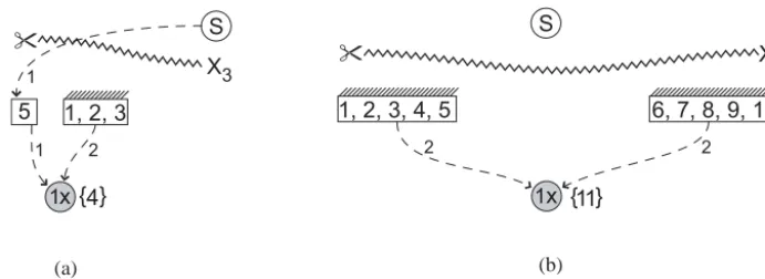
Figure 10.Minimal cuts and resulting DOFs for each substructure.
rected from the “upstream” to the “downstream” side. The sum of weights of the cut edges is termed the weight of the cut, while the sum of implicit equations in the downstream side of the cut is termed the absorbing degree of the cut. The DOF of the cut is equal to its weight minus its absorbing degree. This DOF is equal to the DOF of the nodes on the downstream side of the cut. Whenever the DOF of the cut is less or equal to zero, the downstream subsystem will repre-sent a rigid or an overconstrained subsystem. The cut with the minimal DOF will determine the most overconstrained substructure. Such cuts can be easily determined using state-of-art graph-theoretic methods (Abel and Bicker, 1982).
For example, the cutX1in Fig. 8a displays a weight of 23 and an absorbing degree of 5, which results into a DOF of 18 that correspond to the 18 isolated bar rotations. But since the isolated degrees of freedom need not be taken into account for rigidity detection, only the transmitted isolated DOFs (dashed lines) need to be regarded, leading to the reduced loop connection graph in Fig. 8b, where the weight of cutX1 now can be recognized as 4 with an absorbing degree of 5. Thus, the whole loop transmission structure without isolated DOFs is recognized as over-rigid with DOF= −1. However, as there is an additional structurally isolated DOF entering loopL11, one can recognize a global proper DOF. The ques-tion of which parts are rigid and which parts are movable can be answered by regarding so-called pruned graphs containing subsets of implicit constraints and their predecessor nodes from the root of the loop connection graph, as explained be-low.
As a “pruned” sub-graph, one understands the sub-graph obtained when taking some sinks and removing all nodes that are not on any path from the sink to the source (Fig. 9). Clearly, only one such pruned sub-graph has a cut with non-positive DOF (X2in Fig. 9a). Thus the subsystemL1,L2,L3 can be replaced by a rigid body. Restarting the algorithm with these loops replaced by a rigid body gives Fig. 10a, which again displays a cutX3with DOF=0, hence the subsystem L1,L2,L3,L4,L5is again rigid. Replacing this again by a rigid body and carrying out the analogous steps for the right half of the “double-banana” graph gives the pruned graph of Fig. 10b. This graph has now a cut X4 with transmitted
weight zero (not counting the fully isolated DOF of loopL11) and an absorbing degree of 1, hence the cut has DOF= −1. As a result, the algorithm is able to detect both halves of the “double-banana” as rigid, and also to detect that their assem-bly into loopL11features one structurally isolated DOF.
8 Discussion
The proposed approach shows that by regarding loops as transmission elements and tracking the transmission of iso-lated DOFs through the mechanism one can detect non-trivial cases of rigidity involving implied hinges. Although the method may seem complicated, it can actually be broken down into simple steps for which graph-theoretic algorithms already exist. For example, steps for dissecting a mechanism into kinematical loops and setting up the kinematical network and loop connection graph have already been implemented in Mathematica by our group using well-known graph the-oretical algorithms for finding minimal cycles or minimal cut sets (Kecskeméthy, 1993). The advantage of using loops for transmission evaluation lies evidently in the fact that one can combine substructures of different mobility spaces such as planar, spherical or spatial, and that structurally isolated DOFs can be detected within one loop by regarding the corre-sponding isotropy groups (Kecskeméthy, 1993). Thus, in our opinion this new methodology could prove useful for rigid-ity detection algorithms in other areas of applications. While the automatic implementation of the classification of differ-ent types of isolated DOFs is still to be completed, we be-lieve that this is accomplishable in a general setting. Future research will be devoted to demonstrate that the presented algorithm also holds for so-called nucleation free mecha-nisms (Cheng et al., 2009), which comprise individual mo-bile structures that become rigid and form “implied hinges” once embedded in a certain mechanism.
9 Conclusions
mo-bility and rigidity for systems featuring spherical-spherical pairs, such as the “double-banana” case. The method consists in viewing the mechanism as an assembly of coupled inde-pendent kinematical loops instead of regarding it as a system of coupled bodies and joints (or bars and nodes). Due to this, it is possible to track isolated degrees of freedom separately from transmitted joint angles, and by this to detect rigid sub-systems and “implied hinge” finite mobility for complex sys-tems as the “double-banana” case. In this setting, it is in-teresting to note that this approach is implementable using standard tools from graph theory. Although we have not yet completed this automation, we believe that this is feasible, which is a topic of future research.
Acknowledgements. The financial support of the second author as a Humboldt Research Fellow by the Alexander von Humboldt Foundation is gratefully acknowledged.
Edited by: D. Pisla
Reviewed by: two anonymous referees
References
Abel, U. and Bicker, R.: Determination of All Minimal Cut-Sets between a Vertex Pair in an Undirected Graph, IEEE T. Reliab., R-31, 167–171, 1982.
Agrawal, V. and Rao, J.: Fractionated Freedom Kinematic Chains and Mechanisms, Mech. Mach. Theory, 22, 125–130, 1987. Bennett, D. J. and Hollerbach, J. M.: Autonomous calibration of
single-loop closed kinematic chains formed by manipulators with passive endpoint constraints, IEEE T. Robotic. Autom. 7, 597–606, 1991.
Carretero, J., Podhorodeski, R., Nahon, M., and Gosselin, C. M.: Kinematic analysis and optimization of a new three degree-of-freedom spatial parallel manipulator, J. Mech. Design, 122, 17– 24, 2000.
Casals, A. and Amat, J.: Automatic Guidance of an Assistant Robot in Laparoscopic Surgery, in: Proceedings of the 1996 IEEE Inter-national Conference on Robotics and Automation, Minneapolis, MN, USA, April 1996, 895–900, 1996.
Cheng, J., Sitharam, M., and Streinu, I.: Nucleationfree 3d rigidity, in: In Proceedings of the 21st Canadian Conference on Compu-tational Geometry(CCCG2009), 71–74, 2009.
Chubynsky, M. V. and Thorpe, M. F.: Algorithms for three-dimensional rigidity analysis and a first-order percolation transition, Phys. Rev. E, 76, 041135, doi:10.1103/PhysRevE.76.041135, 2007.
Ding, H., Kecskeméthy, A., and Huang, Z.: Synthesis of the Whole Family of Planar 1-DOF Kinematic Chains and Creation of their Atlas Database, Mech. Mach. Theory, 47, 1–15, 2012.
Ding, H., Huang, Z., and Mu, D.: Computer-aided structure decom-position theory of kinematic chains and its applications, Mech. Mach. Theory, 43, 1596–1609, 2008.
Fanghella, P. and Galletti, C.: Mobility Analysis of Single-Loop Kinematic Chains: An Algorithmic Approach Based on Dis-placement Groups, Mech. Mach. Theory, 29, 1187–1204, 1994.
Fowler, P. W. and Guest, S. D.: Symmetry analysis of the double banana and related indeterminate structures, In New approaches to structural mechanics, shells and biological structures, edited by: Drew, H. R. and Pellegrino, S., 91–100, 2002.
Franzblau, D. S.: Ear decomposition with bounds on ear length, In-form. Process. Lett., 70, 245–249, 1999.
Franzblau, D. S.: Generic rigidity of molecular graphs via ear de-composition, Discrete Appl. Math., 101, 131–155, 2000. Hsu, K., Karkoub, M., Tsai, M.-C., and Her, M.: Modelling and
index analysis of a Delta-type mechanism, P. I. Mech. Eng. K-J. Mul., 218, 121–132, 2004.
Hunt, K.: Kinematic Geometry of Mechanisms, Clarendon Press, Oxford, 334, 1978.
Hwang, W.-M. and Hwang, Y.-W.: An algorithm for the detection of degenerate kinematic chains, Math. Comput Model., 15, 9–15, 1991.
Isaksson, M., Eriksson, A., Watson, M., Brogårdh, T., and Naha-vandi, S.: A method for extending planar axis-symmetric paral-lel manipulators to spatial mechanisms, Mech. Mach. Theory, 83, 1–13, 2015.
Jacobs, D. and Hendrickson, B.: An Algorithm for Two Dimen-sional Rigidity Percolation: The Pebble Game, J. Comput. Phys., 137, 346–365, 1997.
Jacobs, D. J., Kuhn, L. A., and Thorpe, M. F.: Flexible and Rigid Regions in Proteins, in: Rigidity Theory and Applications, edited by: Thorpe, M. and Duxbury, P., Fundamental Materials Re-search, 357–384, Springer USA, 2002.
Jain, A. and Rodriguez, G.: An Analysis of the Kinematics and Dy-namics of Underactuated Manipulators, IEEE T. Robot., 9, 411– 422, 1993.
Kecskeméthy, A.: Objektorientierte Modellierung der Dynamik von Mehrkörpersystemen mit Hilfe von Übertragungselementen, Fortschrittberichte VDI, Reihe 20, Nr. 88, VDI-Verlag, Düssel-dorf, 1993.
Kecskeméthy, A., Krupp, T., and Hiller, M.: Symbolic Processing of Multiloop Mechanism Dynamics Using Closed-Form Kinemat-ics Solutions, Multibody Syst. Dyn., 1, 23–45, 1997.
Laman, G.: On graphs and rigidity of plane skeletal structures, J. Eng. Math., 4, 331–340, 1970.
Lee, A.: Geometric constraint systems with applications in CAD and biology, ph.D. Thesis, 2008.
Lee, A., Streinu, I., and Theran, L.: Finding and Maintaining Rigid Components, in: CCCG’05, 219–222, 2005.
Lee, A., Streinu, I., and Theran, L.: Analyzing rigidity with peb-ble games, in: Proceedings of the Twenty-Fourth Annual Sym-posium on Computational Geometry, SCG ’08, 226–227, ACM, New York, NY, USA, 2008.
Lee, H.-J. and Yoon, Y.-S.: Detection of Rigid Structure in Enumer-ating Basic Kinematic Chain by Sequential Removal of Binary Link String, JSME international journal. Ser. 3, Vibration, con-trol engineering, engineering for industry, 35, 647–651, 1992. Liu, H., Huang, T., Kecskeméthy, A., and Chetwynd, D. G.: A
gen-eralized approach for computing the transmission index of paral-lel mechanisms, J. Mech. Mach. Theory, 245–256, 2014. Maxwell, J. C.: On reciprocal figures, frames and diagrams of
forces, Philos. Mag., 427, 250–261, 1864.
sympo-sium on Virtual reality software and technology, 188–195, ACM, 2003.
Merlet, J.-P.: Kinematics and synthesis of cams-coupled parallel robots, in: International Workshop on Computational Kinemat-ics, Cassino, Italy, May 2005.
Michelucci, D. and Foufou, S.: Interrogating Witnesses for Geo-metric Constraint Solving, in: 2009 SIAM/ACM Joint Confer-ence on Geometric and Physical Modeling, SPM ’09, 343–348, ACM, New York, NY, USA, 2009.
Moinet, M., Mandil, G., and Serre, P.: Defining Tools to Address Over-constrained Geometric Problems in Computer Aided De-sign, Comput. Aided Des., 48, 42–52, 2014.
Moukarzel, C.: An efficient algorithm for testing the generic rigidity of graphs in the plane, J. Phys. A, 29, 8079–8098, 1996. Razmara, N., Kohli, D., and Dhingra, A. K.: On the degrees of
free-dom of motion of planar-spatial mechanisms, Volume 7, in: Pro-ceedings of the 2000 ASME Design Engineering Technical Con-ferences and Computers and Information in Engineering Confer-ence, Baltimore, MD, USA, 2000
Robbins, H.: A theorem on graphs, with an application to a problem of traffic control, Am. Math. Mon., 281–283, 1939.
Rojas, N. and Thomas, F.: The closure condition of the double ba-nana and its application to robot position analysis, in: IEEE Inter-national Conference on Robotics and Automation (ICRA), 6–10, Karlsruhe, Germany, 2013.
Rolland, L.: The manta and the kanuk: Novel 4-dof parallel mecha-nisms for industrial handling, Proc. of ASME Dynamic Systems and Control Division IMECE, 99, 14–19, 1999.
Servatius, B. and Servatius, H.: Rigidity, global rigidity, and graph decomposition, Eur. J. Comb., 31, 1121–1135, 2010.
Servatius, B., Shai, O., and Whiteley, W.: Combinatorial character-ization of the Assur graphs from engineering, Eur. J. Comb., 31, 1091–1104, 2010.
Shai, O. and Müller, A.: A novel combinatorial algorithm for deter-mining the generic/topological mobility of planar and spherical mechanisms, in: ASME 2013 International Design Engineering Technical Conferences and Computers and Information in Engi-neering Conference, V06BT07A073–V06BT07A073, American Society of Mechanical Engineers, 2013.
Shai, O., Sljoka, A., and Whiteley, W.: Directed graphs, decompo-sitions, and spatial linkages, Discrete Appl. Math., 161, 3028– 3047, 2013.
Shiriaev, A. S., Freidovich, L. B., and Gusev, S. V.: Transverse lin-earization for controlled mechanical systems with several pas-sive degrees of freedom, IEEE T. Automat. Contr., 55, 893–906, 2010.
Sljoka, A., Shai, O., and Whiteley, W.: Checking mobility and de-composition of linkages via pebble game algorithm, in: ASME 2011 International Design Engineering Technical Conferences and Computers and Information in Engineering Conference, 493–502, American Society of Mechanical Engineers, 2011. Streinu, I. and Theran, L.: Combinatorial genericity and minimal
rigidity, in: Proceedings of the Twenty-Fourth Annual Sympo-sium on Computational Geometry, SCG ’08, 365–374, ACM, New York, NY, USA, 2008.
Sunkari, R. P.: Structural synthesis and analysis of planar and spa-tial mechanisms satisfying Gruebler’s degrees of freedom equa-tion, PhD thesis, University of Maryland, College Park, Mary-land, 2006.
Sunkari, R. P. and Schmidt, L. C.: Critical Review of Existing De-generacy Testing and Mobility Type Identification Algorithms for Kinematic Chains, ASME Conference Proceedings 2005, 255–263, 2005.
Tay, T.-S.: Rigidity of multi-graphs. I. Linking rigid bodies in n-space, J. Combin. Theory B, 36, 95–112, 1984.
Togashi, J., Matsuda, T., and Mitobe, K.: A low cost and lightweight wire driven robot arm by using elastic strings, in: System Integra-tion (SII), 2014 IEEE/SICE InternaIntegra-tional Symposium, 436–440, IEEE, 2014.
Tuttle, E.: Generation of planar kinematic chains, Mech. Mach. Theory, 31, 729–748, 1996.
Waldron, K.: A Study of Overconstrained Linkage Geometry by Solution of Closure Equations – Part II. Four-Bar Linkages With Lower Pair Joints Other Than Screw Joints, Mech. Mach. Theory, 8, 233–247, 1973.
Whitney, H.: Non-Separable and Planar Graphs, Trans. Am. Math. Soc., 34, 339–362, 1932.
Xia, S., Ding, H., and Kecskeméthy, A.: A Loop-Based Approach for Rigid Subchain Identification in General Mechanisms, in: Proceedings of the ARK, Innsbruck, Austria, 19–26, 2012. Zhang, Y., Finger, S., and Behrens, S.: Introduction to mechanisms,