© 2018 IJSRST | Volume 5 | Issue 3 | Print ISSN: 2395-6011 | Online ISSN: 2395-602X Themed Section: Science and Technology
Development of Closed-Form Solution for a Multi-Layered
Composite Stack Subjected to Thermal Loads
Sanidhya Kumar Sanu1, B K Karthik2, Vijay Vittal3, B Rammohan4Department of Mechanical Engineering, PES University, Bangalore, Karnataka, India
ABSTRACT
Design and assessment of thermal stresses in multi-layered composites has always been area of major concern, as delamination/debonding of the laminae poses a serious issue in the failure of the laminate structure. Stresses at interface can be obtained more swiftly by analytical method when compared to finite element method. In the current work, a comparison has been made between finite element model and first order approximated analytical formulae derived using classical plate theory for a cantilever beam type composite laminate structure with orthotropic material properties. A three-layered structure with orthotropic material properties subjected to uniform thermal load is presented. A comparison has been made among obtained results, Ansys results and the results from similar work carried out in published journal paper. Results obtained from the present work was found to be in close comparison to the Ansys results, stating quantitatively 10.7% from the Ansys results calculated at interface-2, while qualitatively both of them follows the similar trend.
Keywords: Composite laminate, Uniform thermal load, ILSS, Closed-form, Unidirectional lamina, and Multilayered stack
I.
INTRODUCTIONA number of scholars have proposed research models
for multi-layered composite stack, including
experimental and theoretical models. Experimental modeling is a rational approach, but its application entails considerable time and significant expense while in case of theoretical modeling the results can be evaluated in less time and even expenses are less.
Several analytical solutions for multi-layered
structures have been proposed, but most of them can only be applied to isotropic materials. However, a number of applications necessitates orthotropic properties, hence efficient and practically correct estimation of the interlaminar stresses of these structures are vital for the design and evaluation of delamination/debonding failures. Coefficient of thermal expansion (CTE) mismatch is one of the major reason for delamination subjected to thermal stresses in case of adhesively bonded laminates.
Many researchers have deliberately worked on failure mechanics in multi-layered structures among them first was Timoshenko [1], who studied interlaminar stresses in laminate structures and used simple beam theory to calculate curvature of a bimetallic beam under uniform temperature change. Multi-layered beams and plates, with interfacial stresses, thermal stresses, and free-edge problems, was later studied by Grimado [2], Chen and Nelson [3], and others. Their study was focussed on the methods used in structural mechanics, theory of elasticity and elementary methods of strength of materials.
Chen and Nelson [3] derived a closed-form solution to obtain stress distribution in bonded materials for structures used in electronic devices, due to their thermal expansion mismatch.
considered them as a homogeneous body in equilibrium and used ply mechanics to analyze composite laminates. This is called “layer equilibrium”. Rehfield and Valisetty [6] provided another alternative for layer or sub-laminate models, they developed a refined theory for homogeneous plates and laminated structures.
Suhir [7-11] developed a method for predicting interfacial stress in single and multi-layered heteroepitaxial structures. To estimate the thermal stresses in two-layer bonded finite joints he introduced a concept of longitudinal and transverse interfacial compliance and combined them into an engineering approach. Suhir [12] also derived a closed-form equation to determine the magnitude and trend of stresses in bi-material thermostats under uniform temperature change. By making assumptions on the compatibility conditions at the interfaces, he extended his approach to multi-layered thin stacks. Pao and Eisele [13] noted a drawback in Suhir solution, they noticed that it does not satisfy the free boundary condition. Therefore, without imposing additional assumptions on the interface they an extension to multi-layered thin stacks was made from Suhir’s bimetal model.
Wen and Basaran [14] presented a paper which is an addition to the Valisetty’s [15] work, they carried work on the calculation of interlaminar shear stress along the interfaces subjected to thermal load. At the end, a comparison was made between the analytical model results and FEM results. Basaran and Zhao [16] worked on the mesh sensitivity of the laminate structure.
II.
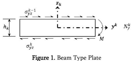
ANALYTICAL METHODFigure 1. Beam Type Plate
Analytical model for a generic N layered composite laminate stack is developed by using general equations in classical plate theory [17] and macro-mechanical analysis of laminates [18] given as follows. Figure 1 represents kth layer for N layered model.
As it is known that orthotropic materials has 9-elastic
constants containing 3-Young's moduli ,
3-Poisson's ratios , and 3-shear
moduli which can be written in
compliance form, as shown below:
(1 )
With plane stress and strain assumption
are set to zero, it’s determined that
relation relating only and , regardless of the fact that is not zero.
(3)
The relation among stresses and strains for the state of plane stress, together with the shear stress-shear strain relation is written as
(4)
The are called the reduced stiffnesses.
Now adding thermal effect into Eqn. 4 gives following equation.
(5)
As every ply has its own fiber orientation, therefore it’s really important to convert them to global coordinate by using transformation matrix [T].
(6)
(7)
(8)
the “compliance matrix ” is defined
by,
(9 )
Using Eqn. 10 to calculate overall force and moment in the composite structure after application of thermal
load .
(10)
N = resultant forces
M = resultant moments
(11)
,
= stiffness matrix
= bending coupling matrix = bending stiffness matrix
The three strains and at any point on the
normal line given the three strains and and
the three curvatures and , and the distance from reference surface.
(12)
Integrating the equation used in classical plate theory and using Eqn. 4 and Eqn. 11 we get the equation for Interlaminar Shear Stress in x andy-direction
(13)
(14)
= Curvature
h = Thickness of each layer
III.
CASE STUDY
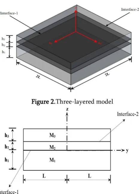
For better clarification, a case study has been taken into consideration for a generic three-layered composite laminate stack with orthotropic material properties [14] subjected to a uniform thermal load of . Thermal loads leads to thermal stresses owing to different CTE in different layers. Figure 2 and Figure 3 describes the geometry of the model and Table.1 indicates the dimension and material properties of the model.
Figure 2.Three-layered model
Figure 3. 2-D view of three-layered model
Table 1. Material properties and dimension of considered model
M1 M2 M3
E1(GPa) 11 15 13
E2(GPa) 140 138 16
E3(GPa) 11 15 13
G12(GPa) 5.5 5.9 2.7
G13(GPa) 5.5 5.9 2.7
G23(GPa) 5.5 5.9 2.7
0.29 0.21 0.16
0.29 0.21 0.16
0.3 0.21 0.16
(e-6/ ) 0.36 0.9 0.5
(e-6/ ) 28.8 23 18
(e-6/ ) 28.8 23 18
h(mm) 0.508 0.0508 0.14
2L(mm) 15.24
In the present model assumed boundary conditions @ y= 0 are
(15)
Using the boundary condition given by Eqn. 15 an Ansys model has been developed and inter-laminar shear stress has been calculated at interface-1 and at interface-2 as shown in Figure 4 and Figure 5.
Figure 3. Ansys Model
Figure 4. Ansys mesh exaggerated view
Layer-3
Layer-2
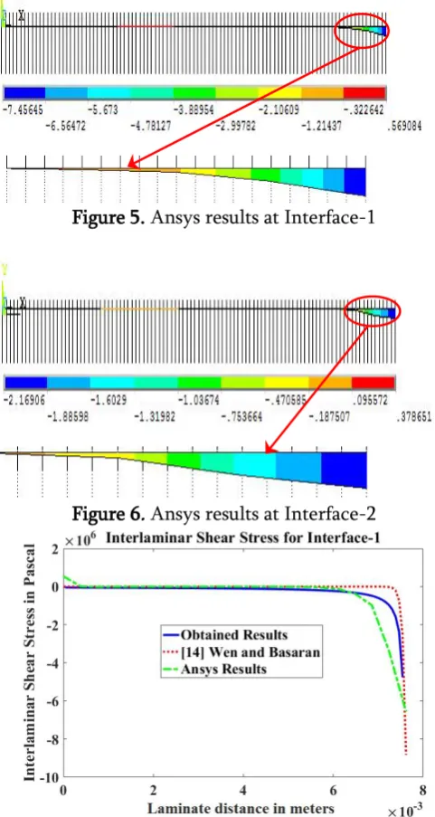
Figure 5. Ansys results at Interface-1
Figure 6. Ansys results at Interface-2
Figure 8. Comparison of ILSS at interface-1 between Derived Model, Wen & Basaran [14] and Ansys
Results
Figure 9. Comparison of ILSS at interface-2 between Derived Model, Wen & Basaran [14] and Ansys
Results
The exaggerated view shown in Figure 6 and Figure 7 shows ILSS in interface-1 and interface-2 respectively at the near free edge.
Again using boundary condition given by Eqn. 15 and using Eqn. 14 to calculate inter-laminar shear stress (ILSS) at interface-1 and interface-2 for which a Matlab code has been developed.
Results from Ansys model, analytical model and the results from equation for work carried out by Wen and Basran [14] are plotted, as shown below.
IV.
RESULTS AND DISCUSSIONS
To calculate the interlaminar shear stress a number of methods were suggested. In the present paper, the method proposed uses stiffness in each layer, overall strain and overall curvature of the laminate stack to calculate ILSS. Overall strain and overall curvature for the structure was calculated by using ABD matrix. ABD matrix was calculated for each layer using the given material properties and was later reduced to single ABD matrix [19], which represented properties for overall structure of the model. Simultaneously, resultant forces and resultant moments were calculated
and resultant forces and resultant moments overall strains and curvatures for the model was calculated as indicated in Eqn. (12). By considering curvatures and thickness of each layer we obtain strains in each layer. Strain obtained from Eqn. (13) represents the strain along the thickness of the considered layer, different approach can be used to obtain the strain distribution along the length of the structure and also to calculate displacements in x, y and z-direction.
The analytical results shown in Figure 8 and Figure 9 was analyzed and compared with two other results which were obtained from Ansys APDL code [20] and from the work carried out by Wen and Basaran [14]. The Ansys mesh model contained in total of 10000 elements which is very fines mesh and according to the study carried out by Basaran and Zhao [16] it is predicted to produce a reasonable result. The results for ILSS at interface-1 and interface-2 were extracted from Ansys model, creating first set of data for comparison. In the work of Wen and Basaran [14], they developed a first-order approximated analytical model to calculate ILSS at different interfaces, using those equations to calculate ILSS at interface-1 and interface-2 creating another set of data for comparison. Using the data extracted from Ansys model, Wen and Basaran model and from Eqn. 14 altogether, graphs were plotted as shown in Figure 8 and Figure 9. Results from Eqn. 14 refers to the method suggested in this paper by using classical plate theory and macro-mechanical approach.
As it can be noticed from Figure 8 and Figure 9 that the distribution of interfacial shear stress at interface-1 and interface-2 is in good agreement to the Ansys results while when compared with the Wen and Basaran model a substantial difference can be noticed. In terms of the quantitative comparison, it has been found that there is difference of 27.5% was found between Ansys results and calculated results at interface-1 and 46% difference between Wen and Basaran model and calculated results. Whereas, for
interface-2 the difference was found to be 10.7% between Ansys results and calculated results and 85.8% between Wen and Basaran model and calculated results. The comparison of results was done for the data at the near free edge.
V.
SCOPE FOR FUTURE WORK
The present work can be extended to laminates subjected to gradient thermal loads and also to laminates with different thermal load. Laminates used in this paper uses unidirectional fiber orientation but it can also be extended to bidirectional fiber orientation.
VI.
CONCLUSIONS
The derived analytical model to calculate ILSS was comparable with the Ansys results. When compared qualitatively both Ansys results and evaluated results follows similar trend. It can also be concluded that compared to Ansys modeling and meshing, a simple calculation by using derived equation can yield faster results.
VII.
REFERENCES
[1]. Timoshenko, S., 1925, "Analysis of Bi-Metal Thermostats", J. Opt. Soc. Am., 11, pp. 233-255.
[2]. Grimado, P. B., 1978, "Interlaminar
Thermoelastic Stresses in Layered Beams", J. Therm. Stresses", 1, pp. 75-86.
[3]. Chen, W. T., and Nelson, C., 1979, "Thermal Stresses in Bonded Joints", IBM J. Res. Dev., 23.2., pp. 179-188.
[4]. Pagano, N. J., 1978, "Stress Fields in Composite Laminates", Int. J. Solids Struct., 14, pp. 385-400. [5]. Pagano, N. J., 1974, "On the Calculation of Interlaminar Normal Stress in a Composite Laminate", J. Compos. Mater., 8, pp. 65-82. [6]. Rehfield, L. W., and Valisetty, R. R., 1984, "A
[7]. Suhir, E., 1986, "Stresses in Bi-Metal Thermostats", ASME J. Appl. Mech., 53, pp. 657-660.
[8]. Suhir, E. 1986, "Stresses in Adhesively Bonded Bi-Material Assemblies Used in Electronic Packaging", Elect. Pack. Mat. Science-II, MRS Symp. Proc., pp. 133-138.
[9]. Suhir, E. 1986, "Calculated Thermally Induced Stresses in Adhesively Bonded and Soldered Assemblies", Int. Symp. Microelect., pp. 383-392.
[10]. Suhir, E. 1987, "Stresses in Multilayered Thin Films on a Thick Substrate, Heteroepitaxy-on-Silicon II", MRS Symp. Proc, 91, pp. 73-80. [11]. Suhir, E. 1988, "An Approximate Analysis of
Stresses in Multilayered Elastic Thin Films", ASME Winter Annual Meeting, WA/APM-14. [12]. Suhir, E., 1989, "Interfacial Stresses in Bimetal
Thermostats", ASME J. Appl. Mech., 56, pp. 595-600.
[13]. Pao, Y.H., and Eisele, E., 1991, "Interfacial Shear and Peel Stress in Multi-Layered Thin Stacks Subjected to Uniform Thermal Loading", ASME J. Electron. Packag., 113, pp. 164-172.
[14]. Wen, Y., and Basaran, C., 2003,
"Thermomechanical Stress Analysis of Multi-Layered Electronic Packaging", ASME J., 125, pp.134-138.
[15]. Valisetty, R. R., and Rehfield, L. W., 1983, "A Theory for Stress Analysis of Composite
Laminates", AIAA Paper 83-0833-CP,
24thAIAA/ASME/ASCE/AHS Structures,
Structural Dynamics, and Materials Conference, Lake Tahoe, NV.
[16]. Basaran, C., and Zhao, Y., 2001, "Mesh Sensitivity and FEA for Multi-layered Electronic Packaging", ASME J. Electron. Packag., 123.3., pp. 218-224.
[17]. O.C. Zienkiewicz, R.L. Taylor, and J.Z. Zhu, 2013 "The Finite Element Method: Its Basis and Fundamentals" Seventh Edition ISBN: 978-1-85617-633-0, Elsevier
[18]. Autar K Kaw, 2006, "Mechanics of Composite Materials", Second Edition, CRC Taylor and Francis
[19]. George Z. Voyiadjis, Peter I. Kattan, 2005, "Mechanics of Composite Materials with Matlab", Springer