IJEDR1801125
International Journal of Engineering Development and Research (
www.ijedr.org
)
723
Abstract - This work describes Security system for banks and jewellery shops. It is very suitable for remote monitoring of
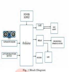
confidential area. Due to increase in bank robbery and theft day by day, security at some places is very important. So the main aim of our project is to provide high security. The ultrasonic radar module includes a transmitter and a receiver mounted on a rotating motor. A motor is used to allow the sensor to cover 360 degree. The ultrasonic sound energy is transmitted from transmitting device into an area of interest and this further reacts to a change in the reflected energy pattern. Basically it works on the principle of echo. It has threshold value. If there is any new echo signal, it compares the signal with threshold value. This case taken as alert and SMS for this alert will send to the concerned person and the nearest police station via GSM MODEM. Then the user will monitor the footage via IP CCTV. If any immediate action needs, the person can send the command over GSM for spraying chloroform in order to prevent theft.
Keywords - Ultrasonic Radar, GSM Module, Arduino, DC motor.
________________________________________________________________________________________________________
I. INTRODUCTION
Radar ISRA (Indonesian Surveillance Radar), the first FWCW maritime radar (Frequency Modulated Continuous Wave) was made in Indonesia, is used to detect and measure the distance of a ship at sea with a low transmit power and does not cause a large radiation. Radar system consists two main parts: transmitter and receiver. The results of detection are shown on Radar display unit, where this unit processes the received signals into information that can be interpreted easily by the users We propose a fast method of ultra wideband (UWB) radar that can be applied to a moving target, having in mind such application as concealed theft detection. We demonstrate the performance of the proposed method using simulations and measurements with static and moving targets. We also compare the computational complexity of the proposed method with that of a conventional method to clarify the feasibility of applying the proposed method to the intended real-time systems.
II. EXISTING SYSTEM
CCTV (closed-circuit television) is a TV system in which signals are not publicly distributed but are monitored, primarily for surveillance and security purposes. CCTV relies on strategic placement of cameras, and observation of the camera's input on monitors somewhere. CCTV is commonly used for a variety of purposes, including Maintaining perimeter security in medium- to high-secure areas and installations. Observing behavior of incarcerated inmates and potentially dangerous patients in medical facilities. Traffic monitoring. Overseeing locations that would be hazardous to a human, for example highly radioactive or toxic industrial environments. Building and grounds security.
III. PROPOSED SYSTEM
Here we have designed RADAR system with help of ultrasonic module which is placed along with the existing CCTV camera. CCTV camera for normal video recording purpose, but ultrasonic RADAR will help to find out theft activity at night time of jewellery shop and bank lockers or any other secret places where this security needed. This ultrasonic RADAR sense the environment periodically, so at normal condition we will get constant echo signal from closed room environment, that echo signal read by micro controller and analyzed. When there is any abnormal echo signal apart from normal signal that will be treated as abnormal action happening in the environment, that may be thief or other moving object. This case taken as alert and SMS or Call for this alert will send to the user via GSM MODEM. By this method when thief enter in room, that instant we can get alert signal, not like existing CCTV footage rewind method by next day. The advantages are
➢ This is the most sensitive security method for shops.
IJEDR1801125
International Journal of Engineering Development and Research (
www.ijedr.org
)
724
Fig. 1 Block DiagramIV. HC-SR04 ULTRASONIC SENSOR
Ultrasonic transmitter emitted an ultrasonic wave in one direction, and started timing when it launched. Ultrasonic spread in the air, and would return immediately when it encountered obstacles on the way. At last, the ultrasonic receiver would stop timing when it received the reflected wave. The principle of ultrasonic distance measurement used the already-known air spreading velocity, measuring the time from launch to reflection when it encountered obstacle, and then calculate the distance between the transmitter and the obstacle according to the time and the velocity. Thus, the principle of ultrasonic distance measurement is the same with radar.
Fig.2 Ultrasonic sensor
The HC-SR04 ultrasonic sensor uses sonar to determine distance to an object like bats do. It operation is not affected by sunlight or black material like. It comes complete with ultrasonic transmitter and receiver module.
A. PRODUCT FEATURES
Ultrasonic ranging module HC - SR04 provides 2cm - 400cm non-contact measurement function, the ranging accuracy can reach to 3mm. The modules includes ultrasonic transmitters, receiver and control circuit. The basic principle of work: Using IO trigger for at least 10us high level signal, The Module automatically sends eight 40 kHz and detect whether there is a pulse signal back. IF the signal back, through high level , time of high output IO duration is the time from sending ultrasonic to returning.
B. ULTRASONIC APPLICATION
Ultrasonic Application Technology is the thing which developed in recent decades. With the ultrasonic advance, and the electronic technology development, especially as high-power semiconductor device technology matures, the application of ultrasonic has become increasingly widespread:
➢ Ultrasonic measurement of distance, depth and thickness
➢ Ultrasonic testing
➢ Ultrasound imaging; Ultrasonic machining, such as polishing, drilling
➢ Ultrasonic cleaning
IJEDR1801125
International Journal of Engineering Development and Research (
www.ijedr.org
)
725
Set low the Trig and Echo port when the module initializes , firstly, transmit at least 10us high level pulse to the Trig pin (module automatically sends eight 40K square wave), and then wait to capture the rising edge output by echo port, at the same time, open the timer to start timing. Next, once again capture the falling edge output by echo port, at the same time, read the time of the counter, which is the ultrasonic running time in the air. Need to supply a short 10uS pulse to the trigger input to start the ranging, and then the module will send out an 8 cycle burst of ultrasound at 40 kHz and raise its echo. The Echo is a distance object that is pulse width and the range in proportion. You can calculate the range through the time interval between sending trigger signal and receiving echo signal. Formula: uS / 58 = centimeters or uS / 148 =inch; or: the range = high level time * velocity (340M/S) / 2; we suggest to use over 60ms measurement cycle, in order to prevent trigger signal to the echo signal. V. STEPPER MOTORStepper motor (also called as step motor) is basically a brushless DC motor, whose rotor rotates through a fixed angular step in response to input current pulse. That means, the full rotation of the rotor is divided into equal number of steps, and rotor rotates through one step for each current pulse. Stepper motors are becoming very popular due to the fact that they can be controlled directly by computers, microprocessors or microcontrollers. Stepper motors are used for precise positioning of an object or precise speed control without closed loop feedback. Stepper motor is a specially designed DC motor that can be driven by giving excitation pulses to the phase windings. They cannot be driven by just connecting the positive and negative leads of the power supply.
A stepper motor is a type of DC motor which has a full rotation divided in an equal number of steps. It is a type of actuator highly compatible with numerical control means, as it is essentially an electromechanical converter of digital impulses into proportional movement of its shaft, providing precise speed, position and direction control in an open-loop fashion, without requiring encoders, end-of-line switches or other types of sensors as conventional electric motors require.
A. WORKING PRINCIPLE AND OPERATION
A stepper motor is a type of DC motor which has a full rotation divided in an equal number of steps. It is a type of actuator highly compatible with numerical control means, as it is essentially an electromechanical converter of digital impulses into proportional movement of its shaft, providing precise speed, position and direction control in an open-loop fashion, without requiring encoders, end-of-line switches or other types of sensors as conventional electric motors require. The steps of a stepper motor represent discrete angular movements, that take place in a successive fashion and are equal in displacement, when functioning correctly the number of steps performed must be equal to the control impulses applied to the phases of the motor. The final position of the rotor is given by the total angular displacement resulting from the number of steps performed.
Speed of a stepper motor can be controlled in a broad range of values by altering the frequency of input impulses. For example if the angular displacement per step is 1,8 degrees, the number of total impulses required for a complete revolution is 200, so for an input frequency of 400 impulses per second the speed of the motor is 120 rpm. Stepper motors can operate with input frequencies up to 2000 impulses (steps) per second, with step values from 0,3 to 180 degrees.
Fig.3 Dc Stepper Motor
Stepper motors work on the principle of electromagnetism. There is a soft iron or magnetic rotor shaft surrounded by the electromagnetic stators. The rotor and stator have poles which may be teethed or not depending upon the type of stepper. When the stators are energized the rotor moves to align itself along with the stator (in case of a permanent magnet type stepper) or moves to have a minimum gap with the stator (in case of a variable reluctance stepper). This way the stators are energized in a sequence to rotate the stepper motor. Get more information about working of stepper motors through interesting images at the stepper motor Insight.
VI. GSM
IJEDR1801125
International Journal of Engineering Development and Research (
www.ijedr.org
)
726
.Fig.4 GSM Module VII. RESULTS
Fig.5 Radar Module
Fig.6 Alert Message Screenshot
VIII. CONCLUSION
We have reported the outcomes of a research and demonstration project on ultrasonic radar sensor for security system for human or object interference in confidential area. By Using a GSM and camera it makes better for any security purpose. The result in this project is genuine and is a product of sincerity and hard work. The system has been successfully implemented and the aim is achieved without any deviation. There is a lot of future scope for this project because of its security capacity. It can be used in many applications. The product can also be developed or modified according to the rising needs and demand.
REFERENCES
[1]. J. L. Crowley, "World Modelling and Position Estimation for a Mobile Robot Using Ultrasonic Ranging," Proc. IEEE Int. Conf. Robotics and Automation, pp. 674-680, 1989.
[2]. H. Choset, K. Nagatani, and N.A. Lazar, "The Arc Traversal Median Algorithm: a Geometric Approach to increase Ultrasonic Sensor Azimuth Accuracy," IEEE Trans Robotics and Automation, vol. 19, no. 3, pp. 513-522, 2003.
[3]. Bari Harshal Sunil, "Household Security System Based on Ultrasonic Sensor Technology with SMS Notification," published under European Journal of Academic Essays 1(4): 6-9, 2014 ISSN: 2183-1904.
[4]. Sungbok Kim and Hyunbin Kim, "Simple and Complex Obstacle Detection Using an Overlapped Ultrasonic Sensor Ring," 2012 12th International Conference on Control, automation and Systems.
[5]. Shinu N Yoannan, Vince T Vaipicherry, Don K Thankachan, Prof. Ram Prasad Tripathy, "Security System Based on Ultrasonic Sensor Technology," IOSR Journal of Electronics and communication Engineering, Sep. – Oct. 2013, pp 27-30. [6]. AdamuMurtalaZungeru, "Design and Development of an Ultrasonic Motion Detector," School of Electrical and Electronic