36 |
P a g e
MAJOR ASPECTS THAT ARE CONSIDERED FOR A PULSE
COMPRESSION TECHNIQUE
Amit Kumar
1and V.K.Singh
2RKGIT(W,Ghaziabad(India))
Abstract
The present project aims to make an in-depth study of Radar pulse compression, Phase Coded pulse compression codes. Pulse compression is a method which combines the high energy of a longer pulse width with the high resolution of a narrow pulse width. The major aspects that are considered for a pulse compression technique are signal to sidelobe ratio (SSR) performance. Matched filtering of biphase coded radar signals create unwanted sidelobes which may mask important information. Hence the study of poly phase codes like six phase pulse compression code is needed and the implementation techniques are carried out since the poly phase codes have low sidelobes and are better Doppler tolerant. The proposed VLSI architecture can efficiently generate Six Phase pulse compression sequences while improving some of the parameters like area and speed when compared to previous methods.
keywords
— FPGA, Pulse compression, Sidelobe energy, Ternary sequence, VLSI architecture.I. INTRODUCTION
The Pulse compression codes with low autocorrelation side lobe levels and high Merit factor are useful for radar [1],
channel estimation, and spread spectrum communication applications. Pulse compression can be defined as a technique
that allows the radar to utilize a long pulse to achieve large radiated energy but simultaneously obtaining the
range-resolution of a short pulse. Theoretically, in pulse compression, the code is modulated onto the pulsed waveform during
transmission. At the receiver, the code is used to correlate with the received signal to achieve a high range resolution.
Range-resolution is the ability of the radar receiver to identify nearby targets. The main criterion of good pulse
compression is the Merit factor and discrimination.
Let S = [S0, S1, S2 .... SN-1] be a real sequence of length N.
Let
Q(K)= (1.1)
Where k=0, 1, 2 ... N-1 is its aperiodic autocorrelation.
The Merit factor F is defined as the ratio of energy in the main peak and the side lobes. The merit factor F must be as
large as possible for good sequence.
37 |
P a g e
Discrimination is used to measure whether coded signal is a good or poor. This means a code with high discrimination is
a good code while a code with low discrimination is a poor code. Discrimination can be defined as a ratio of main peak
of autocorrelation function to the magnitude of peak side lobe value of autocorrelation function.
D= (1.3)
Merit factor is used to measure whether coded signal is a good or poor. This means that a code with high Merit factor is a
good code while a code with low Merit factor is a poor code. Pulse compression can be achieved using different
techniques in which phase coding is the widely used. These include binary, ternary, quaternary, Quinquenary, etc. The
selection of phase coding depends upon the application and requirements.
II. NEED FOR PROPOSED ARCHITECTURE
The problem of obtaining long sequences with peaky autocorrelation has long been an important problem in the field of
radar, sonar and system identification. It is viewed as the problem of optimization. The signal design problem for radar
application is suggested by sequences like binary, Polyphase, ternary and Quinquenary sequences. There has been
extensive work on binary, Ternary and Four Phase sequences for obtaining good merit factor or discrimination. One of
the problems facing the radar pulse compression system designer is the accurate generation of the transmitted waveform,
given that the capability to generate virtually arbitrarily phase-coded waveforms is required. The Hardware
Implementation architectures for Pulse compression signal processing systems available in the literature have the
capability of generating the pulse compression sequences with limited speed. To overcome this drawback we proposed
an area and speed efficient VLSI architecture. The proposed architecture has advantages like it occupies less area, works
faster and because of its 6-bit resolution it generates the pulse compression sequence with very low quantization error
there by the benefit of pulse compression is received.
III. PROPOSED ARCHITECTURE
The proposed model is shown in the Fig. 1.4 It consists of a pair of counters (up and down), memories (ROMs) and a
control circuit and DAC. One memory stores sine amplitude values. The second memory holds the amplitude values of a
sinusoidal waveform which are sampled for every so from 0° to 360° in binary form. Equivalent binary representations
are obtained by using the 8- bit floating point format. The phase shifted analog sinusoidal wave form is produced by
outputting the binary equivalents continuously by controlling with a counter. All the binary values are fed to a DAC to
convert digital equivalents to analog. This conversion is done by using PSoC microcontroller, which consists of inbuilt
digital and analog system. The model has a pair of counters in which one is used as an up-counter and the other as
down-counter. Up-counter assigns the starting count taken from the first memory and controls the continuous outputting of the
sequences. Down counter sets and resets the up-counter using a control circuit. The model's control circuit is simply a
Nand gate. From the functional property of Nand gate, it is known that it produces a low logic when all of its inputs are
set high. The output from the Nand gate is fed to the up-counter for controlling the total counts or cycles of it. The same
clock and clear signals are applied to both the counters. The input sequence is taken to be Barker sequence, which have
reduced side lobe levels compared to other possible code sequences. The input sequence length varies from a single bit to
38 |
P a g e
wide. So, to reset the counter state for every 64 clock cycles, we need additional counter that is implemented using a
down-counter. Exactly after 64 clock cycles, it reaches its initial state thus enabling the control circuit to reset the
up-counter. At this instant, the up-counter is loaded with the starting count obtained from the phase selector. The change in
input sequence causes the phase change and changes the starting count which is stored in the phase selector. Hence this
count is supplied to the up-counter and the 64 clock cycles produce the corresponding samples from the sine memory,
thus producing equivalent analog phase shifted waveform.
Figure.1 VLSI architecture for generation of Radar Pulse Compression Sequences
IV IMPLEMENTATION OF PROPOSED ARCHITECTURE
The Six phase pulse compressed sequence elements are + 1, -I, (0.5+j0.866), (0.5-j0.866), (0.5+j.866), (-0.5-j0.866).
These are +1, -1, (0.5+j0.866), (0.5-j0.866), (-0.5+j.866) and (-0.5-j0.866) are transmitted as sinusoidal signal with 0°
60° 120°, 180°, 240° and 300 degree phase shift respectively. The input is of 3 bits length and elements + 1, -1,
(0.5+j0.866), (0.5-j0.866), (-0.5+j.866), (-0.5-j0.866) are represented by 000,001,010,011,100 and 101 respectively. The
phase selector memory consists of data of six phase values corresponding to 0°, 60°, 120°, 180°, 240° and 300°. When
input "000" is chosen then the phase selector will output the data value corresponding to 0° phase, this data is then given
to the up counter and the up counter then starts its count from 0° to 360° and are given to the input of the sine memory.
Then the sine memory unit will output the amplitude levels corresponding to phases starting from 0° to 360°. When these
values are given to of a converter, it generates a sine wave starting with 0° phase. Similarly, when input "010" is chosen
then sine wave with 120° phase is generated. Hence depending upon the input, one of the phase values is selected from
the phase selector memory. The selected phase value is given to the input of the up counter, and then it generates all the
phase values starting from the phase value selected from the memory. Hence it generates six phase pulse compression
39 |
P a g e
V. SIMULATION AND SYNTHESIS RESULTS
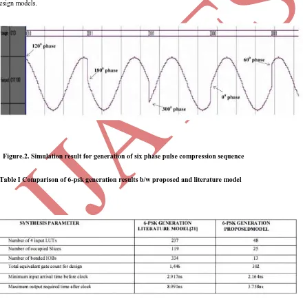
The waveform window in the figure 2 shows the Behavioral simulation results of the generation of the six phase pulse
compression sequence elements (0.5+jO.866), (0.5-jO.866) and (-0.5-jO.866), + 1 and The waveform window in the
figure 2 shows the Behavioral simulation results of the Generation of the six phase pulse compression sequence elements
+ 1, -1, (- 0.5+jO.866) and (0.5+jO.866). From the diagrams we can clearly see that the elements + I, -I, (0.5+jO.866),
(0.5-jO.866), (-0.5+j.866) and (-0.5-jO.866) are transmitted as sinusoidal
signal with phases 0°, 60°, 120°, 180°, 240° and 300° respectively. Table I. shows the design implementation summary
of the proposed architecture and Table II. Shows the comparison of 6-psk generation results between proposed and
literature model, the tables shows that the number of look up tables required for the proposed model is 48, whereas for
the literature model[21] it is 237, hence area is improved. We can also see an improvement of speed and delay with the
proposed model compared to the literature model[21]. Hence the proposed architecture model is efficient than previous
design models.
Figure.2. Simulation result for generation of six phase pulse compression sequence
Table I Comparison of 6-psk generation results b/w proposed and literature model
40 |
P a g e
VI. CONCLUSION
In this paper we have proposed and implemented an area optimized and speed efficient novel VLSI architecture for
generating the pulse compression codes like Binary, ternary, Quinquenary and 6-Phase pulse compression sequences.
The proposed architecture has been authored in VHDL and simulated using Modelsim 6.0 SE and its synthesis was done
with Xilinx ISE Foundation 10.1. The synthesis tool was configured to optimize for area and high effort considerations.
The targeted device was Spartan-3 xa3s1500fgg676-4. The proposed architecture is found to have the following
advantages
1. The proposed architecture is a unique real-time signal processing solution to generate Binary, Ternary,
Quinquenary, Six phase and other poly phase sequences.
2. It is found that the proposed architecture occupies less area while compared to the literature models.
3. It provides minimum signal propagation delay and thus can be used in radar and communication areas.
4. The generated phase coded sine wave has a resolution of 6-bit.Hence quantization error can be minimized.
REFERENCES
[I] E. C. Farnett and G. H. Stevens, "Pulse compression radar," Radar Handbook, Second ed. New York: McGraw-Hill,1990 . [2] Golay M J E 1977 Sieves for low autocorrelation binary sequences. EEE Trans. Inf. Theory IT -23: 43-51
[3] Bernasconi J "Low autocorrelation binary sequences: statistical mechanics and configuration space analysis. J. Phys. 48 : 559-567
[4 ] De Groot C, Hoffman K H 1992 Low autocorrelation binary sequences:enumeration and optimization by evolutionary strategies Optimization 23: 369-384
[5 ] Golay M J E 1972 A class of finite binary sequences with alternate autocorrelation values equal to zero. IEEE Trans. Inf. Theory IT-18: 44 9-450 [6] Golay M J E 1982 The merit factor of long low autocorrelation binary sequences. IEEE Trans. Inf.Theory IT-28: 543-549
[7] Golay M J E 1983 The merit factor of Legendre sequences. IEEE Trans. Inf. Theory IT -29: 934-936. [8] Moharir P S 1975 Generation of the approximation to binary white noise. J. IETE 21: 5-7.
41 |
P a g e
[10 ] Hoholdt T, Justesen J 1988 Determination of the merit factor of Legendre- sequences. IEEE Trans.Inf. Theory IT-34 : 161-164.[11] Golay M J E, Harris D 1990 A new search for skew-symmetric binary sequences with optimal merit factors. IEEE Trans. Inf. Theory 36: 1163-1166.
[12] Jensen J M, Jensen H E, Hoholdt T 1991 The merit factor of binary sequences related to difference sets. IEEE Trans. Inf. Theory IT -37: 617-626 [13] Singh R, Moharir P S, Maru V M 1996 Eugenic algorithm-based for ternary pulse compression sequences. J. Inst. Electron. Telecommun. Eng. 42: 11-19
[14 ] Moharir P S, Maru V M, Singh R 1996 S-K-H algorithm for signal design. Electron. Lett. 32:1648-1649.
[15] Arthur, J.W.: 'Modem SAW-based pulse compression systems for radar applications. Part 2: Practical systems', Electron. & Commun. Eng. April 1996, 7, (6), pp.237-246
[16] Day R. , Germon R. , O'Neill 8., 1997A Pulse Compression Radar Signal Processor, lEE Colloquim on DSP Chip's in Real Time Instrumentation and Display Systems 4 /1-4/5
[17] Day, R.H. Germon, R. O'Neill, B.C. 1998 A real time digital signal processing solution for radar pulse compression" lEE Colloquium on Digital Filters: An Enabling Technology 6/1-6/5.
[18] Balaji .N, Subba Rao. K and Srinivasa Rao.M , "Generation of Quinquenary Pulse Compression Sequences using FPGA" in Proc. of the 8th WSEAS International conference on Multimedia Systems and Signal Processing (MUSP '08 ), pp.280 -286, 2008.
[19] N. Balaji, K. Subba Rao, M.Srinivasa Rao 2010 A Real Time Signal Processing Solution for the Binary Pulse Compression Sequences with Good Merit Factor values, IEEE, pp.(353-357).
[20 ] N. Balaji, K. Subba Rao, M.Srinivasa Rao 2010 Real Time Generation of the Quinquenary Pulse Compression Sequence using FPGA", ACTA ELECTROTECHNICA, pp.(18-24).