AN ACCELEROMETER BASED DIGITAL PEN FOR
HANDWRITEN DIGIT & GESTURE RECOGNITION
Mrs. Prajakta P Shrimandilkar
1, Prof. R.B. Sonawane
2 1,2Department of Electronics (Digital System)
A V C O E Sangamner, Affiliated university of Pune, (India)
ABSTRACT
In the office automation area, many handwritten documents are digitized for ease of backup and transmission.
The demand for digital writing instruments is thus expected to grow rapidly in coming years. There are many
different types of systems already available in the market. An accelerometer-based digital pen for handwritten
digit and gesture trajectory recognition applications is currently active area on research. Recently, we have
developed a prototype of a MEMS (Micro-Electro-Mechanical Systems) based digital writing instrument which
constructed from MEMS accelerometer for capture of handwriting. In this pen type device consist of a triaxial
accelerometer, a microcontroller, and RF wireless module. After this users can use the pen to write digits or
make hand gestures, and the accelerations of hand motions measured by the accelerometer are wirelessly
transmitted to a computer for online trajectory recognition. After measurement of this acceleration signals we
can recognize it by using trajectory recognition algorithm. In the recognition algorithm basically we are using
acceleration acquisition, signal preprocessing and feature generation. After this features are given to the PNN
(Probabilistic Neural Network) classifier for the classification. After this we will be calculate the effectiveness
of the trajectory recognition algorithm for handwritten digit and gesture recognition using the proposed digital
pen.
Keywords: Accelerometer, Microcontroller, RF Wireless Module, Trajectory Recognition
Algorithm
I
I
NTRODUCTIONmotion trajectories. Thus, many researchers have tried to narrow down the problem domain for increasing the accuracy of handwriting recognition systems
In 1964, the first graphics tablet was launched, the RAND Tablet [1] also known as the Grafacon (Graphic Converter). It makes use of electromagnetic resonance to digitize pen motion. In the next 40 years of development, many different well-developed methodologies to digitize handwriting have been proposed. Targeting business and academic institutions, ultrasonic, infrared and optical sensing are currently the most popular technologies for detecting the position of a digital pen on a large area electronic whiteboard. Luidia Inc. and Sanford LP have separately proposed systems, eBeam and mimior respectively, that can modify a conventional whiteboard by placing a receiver in its corner. The receiver uses infrared and ultrasound technologies to translate pen movement into positions which are recorded on a computer. However, the price of the overall system is very expensive, and the active area is limited,
Recently, some researchers have focused on reducing the error of handwriting trajectory reconstruction by manipulating acceleration signals and angular velocities of inertial sensors However, [2] the reconstructed trajectories suffer from various intrinsic errors of inertial sensors. Hence, many researchers have focused to improve effective algorithms for error compensation of inertial sensors to improve the accuracy of recognition. Dong et al. [7] proposed an optical tracking calibration method based on optical tracking system (OTS) to calibrate 3-D accelerations, angular velocities, and space attitude of handwriting motions. The OTS was developed to obtain accelerations of the proposed ubiquitous digital writing instrument (UDWI) by calibrating 2-D trajectories and to obtain the accurate attitude angles by using the multiple camera calibration. However, in order to recognize or reconstruct motion trajectories accurately, the aforementioned approaches introduce other sensors such as gyroscopes or magnetometers to obtain precise orientation. It increases additional cost for motion trajectory recognition systems as well as the algorithm of the trajectory recognition is also becomes complicated.
In this project we have proposed an accelerometer digital pen for handwritten digit & gesture recognition. In this pen type portable device consist of a triaxial accelerometer, a microcontroller, and RF wireless module. The acceleration signals measured by this transmitter are transmitted to the computer by using wireless module. After measurement of this acceleration signals we can recognize it by using trajectory recognition algorithm. In the recognition algorithm basically we are using acceleration acquisition; signal preprocessing, feature generation and PNN classifier. The signal preprocessing procedure consists of calibration, a moving average filter, a high-pass filter, and normalization. In the feature generation it includes the preprocessed acceleration signals of each axis include range and Zero Crossing. These features are given to the as the inputs of classifiers. In this paper, we proposed a probabilistic neural network (PNN) as the classifier for handwritten digit and hand gesture recognition.
PNN. Then we will see the simulation results of the digit and gesture recognition. Finally conclusion given in the last section.
II SYSTEM OVERVIW
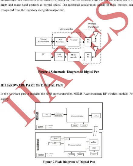
This is the schematic diagram of system which is the digital pen. We will develop a pen-type portable device and a trajectory recognition algorithm. The pen-type portable device consists of a triaxial accelerometer, a microcontroller, and an RF wireless transmission module. The acceleration signals measured from the triaxial accelerometer are transmitted to a computer by using the wireless module. Users can use this digital pen to write digits and make hand gestures at normal speed. The measured acceleration signals of these motions can be recognized from the trajectory recognition algorithm.
Figure 1 Schematic Diagram of Digital Pen
III
HARDWARE
PART
OF
DIGITAL
PEN
In the hardware part, it includes the AVR microcontroller, MEMS Accelerometer; RF wireless module, Power supply.
Figure 2 Blok Diagram of Digital Pen
Triaxial Accelerometer
A/D Converter
Processor RF Tx
PC USB
Driver controller Micro
RF Rx
2.1 AVR Microcontroller
The ATmega16 is a low-power CMOS 8-bit microcontroller based on the AVR enhanced RISC Architecture. By executing powerful instructions in a single clock cycle, the ATmega16 achieves throughputs approaching 1 MIPS per MHz allowing the system designed to optimize power consumption versus processing speed. The AVR core combines a rich instruction set with 32 general purpose working registers. All the 32 registers are directly connected to the Arithmetic Logic Unit (ALU), allowing two independent registers to be accessed in one single instruction executed in one clock cycle. The resulting architecture is more code efficient while achieving throughputs up to ten times faster than conventional CISC microcontrollers. Basically in the microcontroller there are ADC channels. We are use this channels for the conversion of analog data into the digital form.
2.2 MEMS Accelerometer
In this project used the MEMS –ACCELEROMETER -MXA 2300 The MEMS IC device is a complete dual-axis acceleration measurement system fabricated on a monolithic CMOS IC process. The device operation is based on heat transfer by natural convection and operates like other accelerometers having a proof mass except it is a gas in the MEMSIC sensor. A single heat source, centered in the silicon chip is suspended across a cavity. Equally spaced Aluminum/poly-silicon thermopiles (groups of thermocouples) are located equidistantly on all four sides of the heat source (dual axis). Under zero acceleration, a temperature gradient is symmetrical about the heat source, so that the temperature is the same at all four thermopiles, causing them to output the same voltage. Acceleration in any direction will disturb the temperature profile, due to free convection heat transfer, causing it to be asymmetrical. The rising demand for MEMS (micro-electromechanical systems) technology is approaching from diverse industries such as automotive, space and user electronics .so we have developed a prototype of a MEMS (Micro-Electro-Mechanical Systems) based digital writing instrument which constructed from MEMS accelerometer for capture of handwriting
2.3 RF Wireless Module
more range. In the XStream modules the 9600 baud module has 3dB more sensitivity than the 19200 baud module. This means about 30% more distance in line-of-sight conditions. Higher data rates allow the communication to take place in less time, potentially using less power to transmit. So we used this wireless communication media for transmitting the data from microcontroller to the PC for further recognition.
2.4 Power supply
Our project requires +5V for microcontroller and sensors and 3.3V for AVR and RF transceiver module. +5 volt power supply is based on the commercial 7805 voltage regulator IC. This IC contains all the circuitry needed to accept any input voltage from 8 to 18 volts and produce a steady +5 volt output, accurate to within 5% (0.25 volt). It also contains current-limiting circuitry and thermal overload protection, so that the IC won't be damaged in case of excessive load current; it will reduce its output voltage instead.
III TRAJECTORY RECOGNITION ALGORITHM
This Fig 3 is the block diagram of the trajectory recognition algorithm. In this block diagram it includes the acceleration acquisition, signal preprocessing, feature generation and PNN classifier. By using this algorithm we can measure the acceleration signals of hand motions measured by triaxial accelerometer. We will discuss the detail block by block procedure of the trajectory recognition algorithm.
Figure 3 Trajectory Recognition Algorithm
3.1Acceleration Acquisition
3.2 Signal Preprocessing
The acceleration signals of hand motions are generated by the accelerometer and collected by the microcontroller. The signal
Preprocessing consists of calibration, a moving average filter, A high-pass filter and normalization. In the signal preprocessing calibration is used to remove the drift errors. And offset error of accelerations signals. After this signal preprocessing is to use a moving average filter to reduce the high-frequency noise of the calibrated accelerations, and the filter is expressed as:
(1)
Where x[t] is the input signal, y[t] is the output signal, and N is the number of points in the average filter. In this paper, we set
N = 4. The decision of using an four -point moving average filter is based on our empirical tests. From our experimental results, we found that the ideal value of the moving average filter to achieve the best recognition result is four. Then, we utilize a high-pass filter to remove the gravitational acceleration from the filtered acceleration to obtain accelerations caused by hand movement. Then, we use a high-pass filter to remove the gravitational acceleration from the filtered acceleration to obtain accelerations caused by hand movement. In general, the size of samples of each movement between fast and slow writers is different. Therefore, after filtering the data, we first segment each movement signal properly to extract the exact motion interval. Then, we normalize each segmented motion interval into equal sizes via interpolation. Once the preprocessing procedure is completed, the features can be extracted from the preprocessed acceleration signals.
3.3 Feature Generation
In the feature generation the characteristics of different hand movement signals obtained from the accelerometer .we can obtained this by extracting features from the preprocessed x-,
y-, and z-axis signals and we extract Range, Zero crossing in this study.
3.3.1Zero crossing
A zero-crossing is a point where the sign of a mathematical function changes (e.g. from positive to negative), represented by a crossing of the axis (zero value) in the graph of the function. It is a commonly used term in electronics, mathematics, sound, and image processing
.
Zero crossing equation expressed as:(2)
crossing only at one sign function; we do not calculate this zero crossing for another sign function. If there is no zero crossing we can call this state zero. So basically we are checking the zero crossing in the three states.
3.3.2 Range
In the range feature basically we are calculating the starting and ending point of the coordinate of the digit.In the 0 to 9 digit recognition each digit having different range. So in the range feature we calculate the range of x and y coordinates of the digit.
3.4 PNN (Probabilistic Neural Network) Classifier
Figure 4 Probabilistic Neural Network
After this these features will be fed into the PNN classifier to recognize different hand movements. The PNN was first proposed by Specht [14] The PNN is very useful to converge to a Bayesian classifier, and thus, it has a great work for making classification decisions accurately and providing probability and reliability measures for each classification. In the training procedure of the PNN only needs to adjust the weights and biases of the network architecture. Therefore, the most important advantage of using the PNN is its high speed of learning. Basically, the PNN consists of an input layer, a pattern layer, a summation layer, and a decision layer as shown in Fig. The function of the each layer of the PNN is given as follows.
Layer 1: The first layer is the input layer, and this layer performs no computation. The node of this layer given to the input features x to the neurons of the second layer
x = [x1, x2. . . xp]T
p is the number of the extracted features.
Layer 2: The second layer is the pattern layer, and the number of node in this layer is equal to NL. Once a pattern vector x from the input layer arrives, the output of the node of the pattern layer as shown in Fig 4
X 1 2 X 11 X 1i X k1 X k2 X ki ∑ ϕ12 ϕ1i
Layer 3: The third layer is the summation layer. The work of this layer is inputs are summed in this layer to produce the output as the vector of probabilities. Each node in the summation layer represents the active status of one class.
Layer 4: The fourth layer is the decision layer
If the apriori probabilities and the losses of misclassification for each class are all the same, the pattern x can be classified according to the Bayes’ strategy in the decision layer based on the output of all nodes in the summation layer. In this paper, the output of the PNN is represented as the label of the desired outcome defined by users. For example, in our handwritten digit recognition, the labels “1,” “2,” “3,” “4,” “5,”“6,” “7,” “8,” “9,” and “10” are used to represent handwriting digits 1, 2, …, 9, and 0, respectively.
IV OVERVIEW OF THE TRAJECTORY RECOGNITION ALGORITHM
We will discuss the trajectory recognition algorithm in the following steps. Step I: Capture the acceleration signals from the pen type accelerometer module.
Step II: After this filter out the high-frequency noise of the accelerations by the moving average filter in and then remove the gravity from the filtered accelerations by a high-pass filter. In the last, we normalize each segmented motion interval into equal sizes via interpolation.
Step III: Generate the time- and frequency-domain features from the preprocessed acceleration of each axis including range(x,y) zero crossing(x,y)
Step IV: After this feature are given to the PNN classifier.
V EXPERIMENTAL RESULT
In this section, the effectiveness of trajectory recognition algorithm is validated by the following two experiments:
1) Handwritten digit recognition and 2) gesture recognition. The trajectory recognition algorithm consists of the following
Procedures: acceleration acquisition, signal preprocessing, feature generation and PNN classifier
Each participant was asked to hold the digital pen to draw the trajectories of Arabic numerals as shown in Fig. 5 and the pen tip must touch a table.
Figure 5 Trajectories of Arabic Numerals
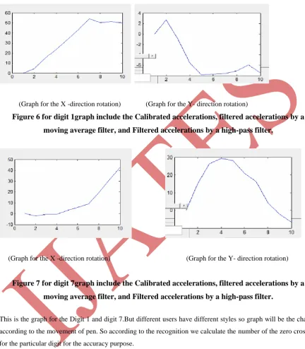
accelerometer module. Subsequently, the acceleration signals were filtered via the moving average filter to reduce the high-frequency noise. Finally, the gravitational acceleration was removed from the filtered acceleration signals via a high-pass filter to obtain the accelerations caused by hand movement .So this is the graph of digit 1 and digit 7.
(Graph for the X -direction rotation) (Graph for the Y- direction rotation)
Figure 6 for digit 1graph include the Calibrated accelerations, filtered accelerations by a
moving average filter, and Filtered accelerations by a high-pass filter.
(Graph for the X -direction rotation) (Graph for the Y- direction rotation)
Figure 7 for digit 7graph include the Calibrated accelerations, filtered accelerations by a
moving average filter, and Filtered accelerations by a high-pass filter.
This is the graph for the Digit 1 and digit 7.But different users have different styles so graph will be the change according to the movement of pen. So according to the recognition we calculate the number of the zero crossing for the particular digit for the accuracy purpose.
VI CONCLUSION
at normal speed. The measured acceleration signals of these motions can be recognize by the trajectory recognition algorithm. Systematic trajectory recognition algorithm framework that can construct effective classifiers for acceleration-based handwriting and gesture recognition. In this project we worked on the trajectory recognition algorithm in which we done acceleration acquisition, signal preprocessing, feature generation, and PNN classifier. PNN can be quickly trained as an effective classifier.
In this project we tried to reduce the complexity of algorithm. Basically we reduced the two important blocks which is the KBCS and LDA. The output of the digital pen is multi stroke output. MEMS accelerometer is the tilt sensing device. Therefore the proper tilting of the sensor is very necessary for accurate handwritten digit and its recognition.
REFERENCES
[1] Malcolm Davis and T. O. Ellis (1964), The RAND Tablet: A Man-Machine Graphical Communications Device.
[2] Z. Dong, U. C. Wejinya, and W. J. Li (2010), An optical-tracking calibration method for MEMS-based digital writing instrument, IEEE Sens. J, vol. 10, no. 10, pp. 1543–1551.
[3] J. S.Wang, Y. L. Hsu, and J. N. Liu(2010), An inertial-measurement-unit-based pen with a trajectory reconstruction algorithm and its applications, IEEE Trans. Ind. Electron., vol. 57, no. 10, pp. 3508–3521. [4] S.-H. P. Won, W. W. Melek, and F. Golnaraghi(2010.), A Kalman/particle filter-based position and orientation estimation method using a position sensor/inertial measurement unit hybrid system, IEEE Trans. Ind. Electron., vol. 57, no. 5, pp. 1787–1798.
[5] S.-H. P. Won, F. Golnaraghi, and W. W. Melek(2009), A fastening tool tracking system using an IMU and a position sensor with Kalman filters and a fuzzy expert system, IEEE Trans. Ind. Electron., vol. 56, no. 5, pp. 1782–1792.
[6] Y. S. Suh (2006.), Attitude estimation by multiple-mode Kalman filters, IEEE Trans. Ind. Electron., vol. 53, no. 4, pp. 1386–1389.
[7] Z. Dong, G. Zhang, Y. Luo, C. C. Tsang, G. Shi, S. Y. Kwok, W. J. Li, P. H. W. Leong, and M. Y. Wong(2007), A calibration method for MEMS inertial sensors based on optical tracking in Proc, IEEE Int. Conf. Nano/Micro Eng, pp. 542–547.
[8] S. J. Preece, J. Y. Goulermas, L. P. J. Kenney, and D. Howard (2005), A comparison of feature extraction methods for the classification of dynamic activities from accelerometer data, IEEE Trans. Biomed. Eng., vol. 56.
[9] L. Bao and S. S. Intill(2009), Activity recognition from user-annotated acceleration data, Pervasive, Lecture Notes in Computer Science, no. 3001 pp. 1–17, 2004. no. 3, pp. 871–879.
[10] Y. P. Chen, J. Y. Yang, S. N. Liou, G. Y. Lee, and J. S. Wang(2008.), Online classifier construction algorithm for human activity detection using a triaxial accelerometer, Appl. Math. Compute, pp. 849–860. [11]A.M. Martinez and A. C. Kak (2001), PCA versus LDA, IEEE Trans. Pattern Anal. Mach. Intell., vol. 23, no. 2, pp. 228–233..