Capacitive Sensor Interfaced with Arduino
Rolan G. Pereira Deeksha A. Naik
UG Student UG student
Department of Electronics & telecommunication Department of Electronics & telecommunication Don Bosco College of Engineering Don Bosco College of Engineering
Shruti S. Naik Shubham D. Naik
UG Student UG Student
Department of Electronics & telecommunication Department of Electronics & telecommunication Don Bosco College of Engineering Don Bosco College of Engineering
Prof. Samantha Cardoso
Assistant Professor
Department of Electronics & telecommunication Don Bosco College of Engineering
Abstract
The present paper gives the detailed analysis of the relationship between Voltage and Capacitance. This conversion from capacitance to voltage is required for the interfacing of electronic microcontrollers. Detection of various dielectrics can be done by using an accurate low capacitance measurement system that can be used to measure small values of capacitances. This capacitance measurement system uses quad two-input NAND Schmitt trigger circuit for the measurement and this system is integrated with Arduino for data acquisition purpose. The Arduino interacts with software developed in the PC end through USB architecture and an attractive Graphical User Interface (GUI) based system is developed in the PC end to provide the user with real time, online display of capacitance under measurement.
Keywords: Schmitt Trigger, Arduino, Data Acquisition, Graphical User Interface
________________________________________________________________________________________________________
I. INTRODUCTION
In recent years the developments of capacitive transducer systems have been an important area of research. Many of these capacitive transducers are employed for measurement of physical quantities like motion, force, acceleration, torque[2]-[6],[10].One of the specific categories of capacitive sensors that require sophisticated instrumentation based measurement systems is the measurement of low value capacitances either in its individual capacity or in a differential form[7]-[9].The methods commonly employed for low capacitance measurement include methods involving AC bridges, charge/discharge methods, oscillation and resonance based method[9],[12],relaxation based method[11] etc. One of the earliest forms of the AC Bridges was Schering bridges which later formed inspiration for the development of various ratio-arm bridges. The later versions of the bridge circuits attempted to improve upon the basic problem associated with bridge circuits that they were not capable of providing sufficient stray-immunity. The charge/discharge method essentially employs the method of charging the unknown capacitance up to a certain voltage level using a switch e.g. a CMOS switch and then discharging that capacitor using another switch. This differential circuit gained popularity because it can reduce drifts caused by common inputs and it is capable of providing good accuracy even for high frequency operation in the range of MHz’s .In oscillation methods RC or LC oscillators can be used to provide a frequency as a function of unknown capacitance and a frequency to voltage converter can be used to measure the unknown capacitance[9].Although these methods are quite simple and accurate for medium capacitance measurement as they cannot eliminate the effect of stray capacitance in their measurement system.
There are two types of capacitive sensors: - Passive
- Active
II. BLOCK DIAGRAM
Fig. 1: Block Diagram of capacitance meter interfaced with Arduino
The block diagram of the capacitance meter interfaced with Arduino is shown above. The capacitance meter is connected to the Arduino via an analog pin. Two plates are connected to the capacitance meter between which dielectric is placed. Based on the different dielectrics the output of the capacitance meter varies.
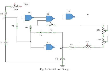
III. CIRCUIT LEVEL DESIGN
Fig. 2: Circuit Level Design
IV. METHODOLOGY
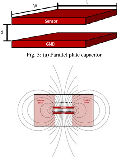
Capacitance is the ability of a capacitor to store electrical charge. A common form-a parallel plate capacitor-the capacitance is calculated by C=Q/V, where C is the capacitance related by the stored charge Q at a given voltage V. The capacitance (measured in Farad) of a parallel plate capacitor consist of two conductor plates and is calculated by :
C=Ɛo * Ɛr * A/d - A is the area of the two plates (in meters)
- Ɛr is the dielectric constant of the material between the plates. - Ɛo is the permittivity of free space (8.85x10^-12 F/m) - d is the separation between the plates (in meters)
The plates of a charged parallel plate capacitor carry equal but opposite charge spread evenly over the surface of the plates. The electric field lines start from the higher voltage potential charged plate and at the lower voltage potential charged plate. The parallel plate equation ignores the fringing effect due to the complexity of modelling the behaviour but is a good approximation if the distance (d) between the plates is small as compared to other dimensions of the plates so the field in the capacitor over most of its area is uniform. The fringing effect occurs near the edges of the plates, and depending on the application, can affect the accuracy of the system. The density of the field lines in the fringe region is less than directly underneath the plates since the field strength is proportional to the density of the equipotential lines. This results in weaker field strength in the fringe region in a much smaller contribution to the total measured capacitance.
Fig. 3: (a) Parallel plate capacitor
Fig. 4: (b) Electric fields of a parallel plate capacitor
The graph which is obtained on the CRO which is the output from the capacitance meter is shown below:
Fig. 5: Where:
T is the pulse period. τ is the duty cycle. Vp is the peak value. Consider the equation:
Vdc is the output voltage which is measured on the multimeter. Vp and T are constants. τ =RC
Therefore, Vdc is directly proportional to R and C.
Also R is a constant and hence Vdc becomes proportional to C. This shows that the value of unknown capacitance can be calculated by measuring the voltage.
V. IMPLEMENTATION
The capacitive meter is used to measure capacitance in terms of voltages. The capacitive meter interfaced with an Arduino can detect materials of different dielectrics constants. Voltage levels are obtained from an externally connected capacitor to the Capacitance meter. Capacitance changes with dielectric constants, which is directly proportional to the voltage between the plates. The voltage is fed to the Arduino. The Arduino, maps the analog values ranging from 0-1023. Various dielectric materials can be classified into ranges and hence can be detected. A threshold is obtained for all detectable materials. These thresholds are then programmed into the Arduino. The Arduino will then compare the voltages when the materials are placed in between the plates. If it matches with the threshold set for the respective material its output is high indicating the waste is detected.
VI. TABLE
Distance(inch) Plates(30cmX30cm) Plates(7cmX7cm)
Capacitance(pF) Voltage(mV) Capacitance(pF) Voltage(mV)
0 Infinite 640 infinite 420
1 31.3 544 17 312
2 15.69 504 - -
3 10.46 480 --
VII. GRAPHS
For plates of 30cmX30cm
VIII. COMPONENTS
Op-Amp (IC 741)
Fig. 6: Op Amp
The LM741 series are general-purpose operational amplifiers which feature improved performance over industry standards like the LM709. They are direct, Exceeded plug-in replacements for the 709C, LM201, MC1439,and 748 in most applications. The amplifiers offer many features which make their application nearly fool proof: overload protection on the input and output, no latch-up when the common mode range is exceeded, as well as freedom from oscillations.
The LM741C is identical to the LM741 and LM741A except that the LM741C has their performance ensured over a 0°C to +70°C temperature range, instead of −55°C to +125°C.
Applications
- Comparators - Multivibrators - DC Amplifiers - Summing Amplifiers - Integrator or Differentiators - Active Filters
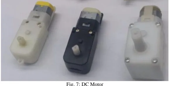
DC Motor
Fig. 7: DC Motor
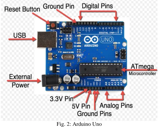
Arduino Uno
The Arduino Uno is a microcontroller board based on the ATmega328(datasheet).It has 14digital input/output pins (of which 6 can be used as PWM outputs),6 analog inputs,a 16MHz crystal oscillator,a USB connection,a power jack,an ICSP header,and a reset button.
Fig. 2: Arduino Uno
IX. CONCLUSION
The capacitive sensor can be used to separate various materials either by changing the dielectric constant between the plates or as a weight sensor by changing the distance between the plates. We can also differentiate between wet waste and dry waste since wet waste has moisture (water) in it which has a dielectric constant of 80.
REFERENCES
[1] David Wang,”Basics of Capacitive sensing and Application,”Texas instruments,December 2014
[2] M. Yamada, T. Takebayashi, S. Notoyama, and K. Watanabe, “A switched-capacitor interface for capacitive pressure transducer,” IEEE Tran. Instrumentation and Measurement, vol. 41, no. 1, pp. 81-86, February 1992.
[3] F. N. Toth and G. C. M. Meijer, “A low-cost, smart capacitive position
[4] Y. C. Chung, N. N. Amarnath, and C. M. Furse, “Capacitance and inductance sensor circuits for detecting the lengths of open- and shortcircuited wires,” IEEE Tran. Instrumentation and Measurement, vol. 58, no. 8, pp. 2495-2502, August 2009.
[5] J. C. Lotters, W. Olthuis, and P. Bergveld, “A sensitive differential capacitance to voltage converter for sensor applications,” IEEE Tran. Instrumentation and Measurement, vol. 48, no. 1, pp. 89-96, February
1999.
[6] A. L. Hugill, “Displacement transducers based on reactive sensors in transformer ratio bridge circuits,” Journal of Physics E: Sci. Instrm. vol. 15, pp. 597-606, 1982.
[7] D. Mariolo, E. Sardani, and A. Taroni, “Measurement of small capacitance variation,” IEEE Tran. Instrumentation and Measurement, vol. 40, no. 2, pp. 426-428, April 1991.
[8] D. M. G. Preethichandra and K. Shida, “A simple interface circuit to measure very small capacitance changes in capacitance sensors,” IEEE Tran. Instrumentation and Measurement, vol. 50, no. 6, pp. 1583-1586,
December 2001.
[9] S. M. Huang, A. L. Stott, R. G. Green and M. S. Beck, “Electronic transducers for industrial measurement of low value capacitances,” Journal of Physics E: Sci. & Instrum., vol. 21, pp. 242-250, 1988
[10] Y. Masuda, M. Nishikawa, and B. Lchijo, “New methods of measuring capacitance and resistance of very high loss materials at high frequencies,” IEEE Tran. Instrumentation and Measurement, vol. IM-29,
pp. 28-36, 1980.
[11] K. Kobayashi, S. Okamoto, and M. Sukigara, “A capacitance relaxation method for studying surface states at the semiconductor-liquid junction,” J. Electroanal. Chem., vol. 225, pp. 79-92, 1987.