Vol. 1, No. 1, pp. 61-70, June (2018)
Adaptive Gain Scheduling Control of Doubly Fed Induction Generator Based
Wind Turbines to Improve Fault Ride Through Performance
Ahmad Khajeha)andZahra Shabanib)
The Doubly-Fed Induction Generators (DFIG) based Wind Turbines (WT) are widely used in WTs connected to power systems. Traditionally the back-to-back converters are used in order to control the DFIG. In this paper, an Indirect Matrix Converter (IMC) is utilized. Compared with back-to-back converters, IMCs have numerous advantages such as: higher level of robustness, reliability, reduced size and weight due to the absence of bulky electrolytic capacitor. According to the recent grid codes it is required that wind turbines remain connected to the grid during grid faults. It means that the plant must be in operation and be able to tolerate the fault conditions. This feature is called Fault Ride-Through (FRT) capability of wind plants. To improve FRT capability of the wind turbine, in this paper an adaptive gain scheduling controller is proposed. The proposed method could increase the damping of fault currents and hence attribute more time to controller for reactive power injection. Therefore, the new FRT standards are satisfied. PSIM simulation results confirm the efficiency of the proposed method.
A B S T R A C T
ARTICLE INFO
Keywords:
DFIG FRT
Indirect matrix converter Wind turbine
Article history:
Received February. 26, 2018 Accepted Aprill. 11, 2018
I. INTRODUCTION
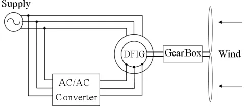
Due to their superior characteristics, most of the grid-connected WTs operate at a variable speed. Among the different variable speed types, the DFIG is the most promising one1. The basic configuration of a WT based on the DFIG is shown in Fig 1. The stator winding of DFIG is directly connected to the grid, while the rotor winding is connected to the grid through an ac-ac power electronic converter having bidirectional switches. Tra-ditionally the back-to-back converters are used to excite the rotor circuit of DFIG. The presence of dc-link capaci-tor in this arrangement is a serious drawback as increases the costs and reduces the overall lifetime of the system and also makes the system bulky2.
In this paper, the back-to-back converter arrangement is replaced by an indirect matrix converter (IMC) to con-trol the generator. The main advantages of a matrix
a)Corresponding Author: [email protected], Tel: +82-2-554-0185, Fax: +82-2-554-0186, Faculty of Electrical and Computer Engineering, University of Sistan and Baluchestan, Zahedan, Iran b)[email protected], Department of Mathematics, Faculty of Mathematics, University of Sistan and Baluchestan, Zahedan, Iran
http://dx.doi.org/10.22111/ieco.2018.24173.1012
converter are: robustness, reliability with less size and weight due to the absence of the bulky electrolytic ca-pacitor, controllable input power factor, nearly sinusoidal input current and output voltage with only switching fre-quency harmonics, along with bidirectional power flow. The direct matrix converter (DMC) encounters the com-mutation problems requiring a complex control circuitry. While in IMC all switches at the line side will turn on and off at zero current, so the commutation problems are eliminated3. Therefore, the IMCs are the most promis-ing devices for wind energy applications regardpromis-ing their robustness, reduced size and reliability concerns.
In the past, based on most grid codes, wind turbines were allowed to be disconnected from the grid during the grid disturbance and abnormal voltage reduction. With the increased capacity of wind powers in the power sys-tems over the years, a sudden loss of wind turbines dur-ing the grid faults resultdur-ing from turbines disconnection could generate control problems of frequency and volt-age in the system so leading to the voltvolt-age collapse in worst case. The increased penetration of wind energy into the power system over the last decade has there-fore led to a serious concern about its influence on the dynamic behavior of the power system. To handle this issue the grid codes are revised by system operators in several countries4. According to the new grid codes the wind turbines must be remain connected to the network on the occurrence of grid fault and tolerate the resulting voltage drops. This feature is known as the fault ride-through (FRT) capability of a power plant. The FRT re-quirement defines that the grid voltage can be how long and how deep at which the wind turbines are allowed to be disconnected from grid. Moreover, in some grid codes such as Germany, wind turbines should also inject reactive power to help the grid voltage recovery.
the wind turbines, can cause voltage drops at the point of wind turbine connection. The abrupt drop of the grid voltage will make an increase in the current of stator windings of the DFIG. Because of the magnetic coupling between stator and rotor, this current will also flow in the rotor circuit and the power converter. At present, the back-to-back converter is the most frequently used power electronic converter in the wind turbines industry. Therefore, the most of research works have been done to enhance the FRT ability of DFIG utilizing this type of converters. So the grid faults cause over current in the rotor windings and over voltage in the dc-link capac-itor hence the proper protection should be provided to safekeeping the converter. Various solutions have been proposed to solve the problem. Some of them are briefly reviewed as follows.
The most popular and reliable method is based on the use of a protective circuit known as crowbar. The crow-bar consists of resistors connected to the rotor windings by means of electronic switches. In active crowbar the switches are controllable such as IGBTs whereas in pas-sive one they are anti parallel thyristors. The active crow-bar allows opening the circuit when the currents reach to safe region. The passive crowbar allows closing the cir-cuit but not to open it until the crowbar currents reach to zero. Therefore, according to the new grid codes, the passive crowbar is not appropriate for the modern wind turbines. When a fault occurs, the rotor windings get connected to the crowbar while the converter is tripped. Several papers have discussed the implementation and control of crowbar5–11. The crowbar can effectively pro-tect the rotor converter under serious grid faults. But its main drawback is that, when the crowbar is activated, the rotor converter cannot control the active and reactive power during crowbar activation so, the DFIG operates as a cage induction generator, absorbing extra reactive power from the grid and deteriorates the grid voltage profile.
Another approach is to modify the rotor-side converter control system to limit the fault currents without using any extra hardware circuit12–19. In this method at se-rious grid faults, the required voltage in the rotor-side converter becomes too large and exceeds its voltage ca-pability. Therefore, the rotor current greatly increases thus leading to converter destruction. This method is beneficial as it does not require any additional hardware but applicable only for moderate faults.
Another solution for FRT is to use an additional en-ergy storage system (ESS) connected to the dc-link20–23. The ESS can balance the extra power that goes through the rotor circuit during a grid fault transient, but it also requires a rotor side converter with higher current ratings having extra cost and more system complexity.
Utilizing matrix converters in DFIG wind turbines is still in research phase. Most of the works have dealt with their normal operation. Sigma-delta modulator to con-trol IMC switches of DFIG based WT is proposed in24. By using this modulation method, torque pulsations and
FIG. 1. Wind turbine based on the DFIG.
harmonic content of currents are reduced. Therefore, the power quality of WT is improved. The capability of the input converter to generate different virtual dc-link volt-age levels is also proposed in25. This method reduces both the commutation losses of output converter and common mode voltage. Due to small voltage required around the synchronous speed, this strategy is applica-ble in DFIG applications.
Dynamic performance of DFIG using two-stage IMC under voltage dip condition has been discussed in26 with-out providing any protection. As simulation results show for 80% terminal voltage sag, the stator current reaches to 2.5 pu. Without any protection method, this high current can damage the IGBT switches of the IMC. Ac-cording to new FRT standards it is required the reactive power to be injected to improve the recovery of voltage during and after grid faults. Results of26 indicate that, during the fault, about 0.7 pu reactive power is absorbed from the grid which make the voltage deeper. There-fore, the existing controller which is designed for normal operating condition is ineffective during fault conditions. To solve these drawbacks and satisfy the new FRT standards, in present paper a new method is proposed to protect the IMC with DFIG following the grid faults. In this method an adaptive controller (instead of conven-tional PI controller) is designed. The proposed method increases the damping of rotor currents. So, the reac-tive power injection is achieved faster and the new FRT standard is well satisfied. The PSIM simulation results confirm the efficiency of the proposed method.
II. FRT REQUIREMENT
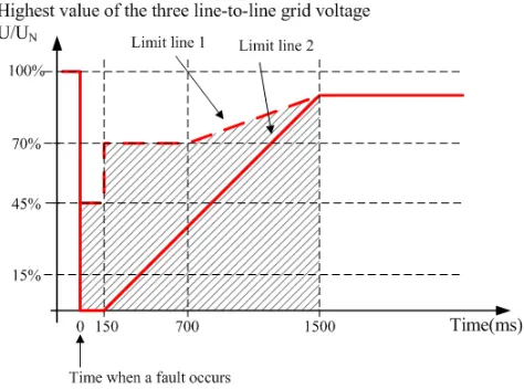
FIG. 2. E. ON Netz LVRT requirement.
line 1 in Fig. 2 or disconnection of the wind turbines from the grid. Within the shaded area and above limit line 2 in Fig. 2, FRT is also required but in case of insta-bility a short term interruption (STI) is allowed. Below the limit line 2 in Fig. 2, no FRT is required and STI from the grid is always permissible. Here, resynchroniza-tion times of more than 2 seconds and an active power increase following fault clearance of less than 10% of the rated power per second are also possible. According to the E.ON Netz grid code, wind turbines have to provide a mandatory voltage support during voltage dips. Wind turbines have to supply 1 pu reactive current when the voltage falls below 0.5 pu.
III. MODELING AND CONTROL OF DFIG BASED WIND TURBINE
In this section, dynamics model of both electrical and mechanical parts of DFIG based wind turbine is pro-vided. The stator winding of DFIG is directly con-nected to the grid, and the rotor winding is coupled via an IMC. The IMC must handle the slip power, i.e. about 30% of the rated power of wind turbine. The speed range of the generator is typically of synchronous speed, thus providing flexibility to operate in both sub and super synchronous modes, depending on the wind conditions. The inverter of the IMC is used to control the active and reactive power of the DFIG. The recti-fier of the IMC is often operated at unity power factor. Depending on the rotor speed, the IMC will either ab-sorb power (sub-synchronous) from grid or inject power (super-synchronous) to the grid. Therefore, the IMC must have the ability of bidirectional power flow to the network.
A. Turbine model
The mechanical power extracted by a wind turbine
from the wind is expressed by
P =1
2A.ρ.Cp(λ, β).v 3
w (1)
whereAis the area covered by the rotor blades,ρis the air density, Cp is the power coefficient, representing the
amount of power the turbine can extract, and vw is the wind speed. The power available in the wind cannot be extracted completely. Theoretically the maximum cap-tured power is 59% of the power available in the wind. The power coefficient is a function of the tip-speed ratio λand the pitch angle of the rotor bladesβ. The tip-speed ratio is defined by
λ= RΩt vw
(2)
WhereR is the radius of the rotor blades and Ωt is the
angular speed of the blades. For each pitch angle of the rotor blades, there is an optimum tip-speed ratioλoptfor
whichCp(λopt, β) takes a maximum value.
B. Drive train
Despite of the complexity of the drive train system in a real wind power plant, the dynamic model is reduced to a two- mass system. To assess the dynamic behavior the drive train needs to be considered. For modeling the drive train knowledge of gear transmission ratio, the stiffness c and the damping coefficient d of the shaft is required. The drive train system is described by
TR=JR.dΩdtR + (ΩR−ΩG).d+ (θR−θG).c
TG =−JG.dΩdtG + (ΩR−ΩG).d+ (θR−θG).c
ΩG=GΩR
(3)
WhereT is torque, J is moment of inertia, Ω is angular speed, andγis angle. SubscriptsRandGrepresent rotor and generator side respectively.
C. DFIG model
For DFIG modeling a fifth-order dynamic model of the DFIG is used in this paper. The model in a two-axisd−q synchronous reference frame given by
vsd=Rsisd+
dΨsd
dt −Wsψsq
vsq=Rsisq+
dΨsq
dt +Wsψsd
vrd=Rrird+
dΨrd
dt −(Ws−Wr)ψrq
vrq=Rrirq+
dΨrq
dt + (Ws−Wr)ψrd
Tem=
p
2(ψrqird−ψrdirq)
FIG. 3. Indirect matrix converter topology.
ψsd=Lsisd+Lmird
ψsq =Lsisq+Lmirq
ψrd=Lmisd+Lrird
ψrq =Lmisq+Lrirq
Ls=Lls+Lm
Lr=Llr+Lm
(5)
In these equations,Rs,Rr, Ls, Lr,Lls, andLlr are the
resistors and inductors of the stator and rotor windings, Lmis the magnetizing inductance,vsd,vsq,vrd,vrq,isd,
isq, ird, irq, ψsd, ψsq, ψrd, andψrq, aredandq
compo-nents of the space vectors of the stator and rotor voltages, currents, and fluxes respectively, Ws is the synchronous
speed of generator, Wr is the electrical speed of rotor,
andpis the number of poles.
D. Indirect Matrix Converter
Due to the numerous advantages of matrix converters over back to back converters, in this paper the IMC is used to control the DFIG. An IMC consists of a rectifi-cation part on the input side and an inversion part on the output side, connected via fictitious dc-link as shown in Fig. 3. For purposes of analysis, we can assume that the switching frequency is far greater than the fundamental frequency of both the input voltage and output current. Thus during each switching cycle, it is assumed that both input voltage and output current are constant.
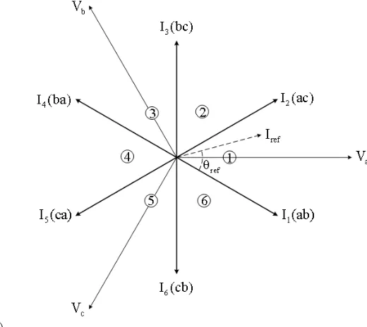
The rectifier has six bidirectional switches with the ability of conducting current and blocking voltage in both directions. The rectifier side objective is to achieve max-imum positive voltages at the fictitious dc-link and sinu-soidal input currents. Usually the grid side converter of DFIG exchanges zero reactive power at the grid point. In order to obtain maximum dc-link voltage, the input phase voltage which has the highest absolute value is con-nected to the positive or negative rail of the dc-link at 60 degree intervals depending on its polarity. To achieve si-nusoidal current and unity power factor at the input side,
FIG. 4. Space vectors of the input current.
regardless of the load type, the other two phase voltages modulated so that the reference current space vector be in phase with the voltage space vector. Space vectors of the input current are shown in Fig. 4. Assume the input voltages are
va=Vmcosθa =Vmcos(wit)
vb=Vmcosθb=Vmcos(wit−
2π 3 )
vc=Vmcosθc=Vmcos(wit+
2π 3 )
(6)
where Vm is the maximum of the input phase voltage and wi is the angular frequency. In order to achieve unity power factor at the input side, the input currents must be in phase with the input voltages. Therefore, input currents are as follows
Ia=Imcos(wit)
Ib=Imcos(wit−
2π 3 )
Ic=Imcos(wit+
2π 3 )
(7)
using two adjacent vectors of each section. For example, when the reference current space vector is located in the first section, two adjacent vectors are ab and ac. In this section, voltage of phase a has the highest absolute value. Therefore, in 60 degree duration of this section, the top switch of phase a is ON and the bottom switches of phases b and c get modulated. Vector ab means the top switch of phase a and the bottom switch of phase b are ON, and ac means the top switch of phase a and the bottom switch of phase c are ON and so on.
So in one period of switching frequency in this section, input currents are as follows
ia= (dab+dac)idc
ib=−dabidc
ic=−dacidc
(8)
wheredabanddacare the duty cycles ofI1(ab) andI1(ac) respectively, and idc is the dc-link current. As only the
active vectors are used, the following relationships hold dab+dac= 1⇒ia=idc (9)
Therefore, the duty cycles of active vectors in the section one are given by
dab=−
ib
ia
dac=−
ic
ia
(10)
The duty cycles in the other sections are obtained simi-larly. Based on this modulation method in the rectifier stage, the average fictitious dc-link voltage in each period is
Vdc=
3.Vm
2.|cos(θin)|
|cos(θin)|= max(|cos(θa)|,|cos(θb)|,|cos(θc)|)
(11)
whereθin is the angle of the input voltage space vector.
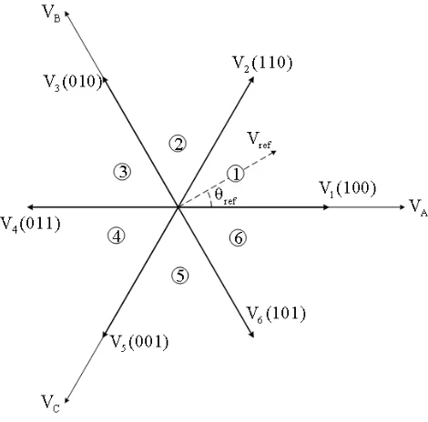
On the output stage, the space vector modulation (SVM) is used to generate the required rotor voltage space vector by currents controllers. Inverter voltage space vectors along with the reference vector are shown in Fig. 5.
Duty cycles of active vectors on the inverter stage are as follow
dα=k.sin(60◦−θi)dβ=k.sin(θi) (12)
wherekis the modulation index and is given by
k=2.|cos(θin)|. ˆ Vr
√
3.Vm
(13)
where Vr is the absolute of the reference voltage.
Con-sidering modulation of both the input and output sides, the final duty cycles of active vectors are
dαγ =dγ.dαdβγ=dγ.dβ
dαδ=dδ.dαdβδ=dδ.dβ
(14)
FIG. 5. Space vectors of the output voltage.
wheredγ is the first vector of the rectifier section anddδ
is the second vector of the rectifier section. Finally, the duty cycles of the zero vectors are calculated as
d0= 1−(dγ+dδ).(dα+dβ)
d0γ=
dγ
(dγ+dδ)
d0d0δ=
dδ
(dγ+dδ)
d0
(15)
IV. VECTOR CONTROL OF DFIG
The goal of the DFIG controller is the independent control of the stator active and reactive power. The ac-tive power reference is determined by MPPT algorithm and the reactive power is set in order to achieve the de-sired power factor. Stator flux d-q reference frame is the most widely used DFIG vector control in the wind tur-bine applications. Thus, the inverter of IMC is controlled in a stator flux d-q reference frame, with the d-axis ori-ented along the stator flux vector position. For this ref-erence frame selection, the DFIG model can be written as
Substituting (16) into (5), we obtain
ids=
1 Ls
(ψs−Lmidr)
iqs=−
Lm
Ls
iqr
ψdr=σLridr+
Lm
Ls
ψs
ψqr=σLriqr
σ= 1− L
2
m
LsLr
(17)
In these equations, σis the leakage factor. These equa-tions are derived by assuming that the power grid is in-finite, so the voltage and frequency are constant. There-fore, the dynamic of the stator flux does not need to be considered, and the stator flux is constant. These as-sumptions yield
dψsd
dt = dψsq
dt = dψs
dt = 0 (18)
In DFIG, the rotor voltages are control variables which control the rotor currents. Substituting (17) into (4), rotor voltages can be written as
vdr=Rridr+
d
dt(σLridr+ Lm
Ls
ψs)
−(Ws−Wr)(σLriqr)
vqr =Rriqr+
d
dt(σLriqr)
+ (Ws−Wr)(σLridr+
Lm
Ls
ψs)
(19)
In dynamic performance analysis of the overall system, cross-coupling terms in (19) are added to control loops as feed-forward compensation terms. The stator active and reactive power can be calculated as
Ps=
3
2(vdsids+vqsiqs)
Qs=
3
2(vqsids−vdsiqs)
(20)
In steady state, the stator flux is proportional to the grid voltage. Neglecting the small voltage drop in the stator resistance yields
Vs=vqs,0 =vds
|V s| 'ws|ψs|
(21)
Thus, when orienting the d-axis with the stator flux, the voltage aligns with the q-axis. Combining (21) and (16)
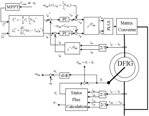
FIG. 6. Schematic diagram of vector control of DFIG.
with (20), we obtain
Ps=
3
2vdsids=− 3 2Vs
Lm
Ls
iqr
Qs=
3
2vqsids= 3Vs
2Ls
(ψs−Lmidr)
(22)
The above equations clearly show that under the stator flux orientation, the active and reactive powers are de-coupled and can be controlled via the rotor currents. By means ofiqr, we can control the active power while the
reactive power can be controlled via theidr. Using the
above equations, the reference currents can be calculated from the desired powers. The schematic diagram of sta-tor flux based vecsta-tor control of DFIG is shown in Fig. 6.
V. ADAPTIVE CONTROL
equations, (19) is modified as below
vrd=Rrird+Lσr
dird
dt −wslipLσrirq
−wslip
Lm
Ls
ψsq+
Lm
Ls
dψsd
dt
vrq=Rrirq+Lσr
dirq
dt +wslipLσrird
+wslip
Lm
Ls
ψsd+
Lm
Ls
dψsq
dt
(23)
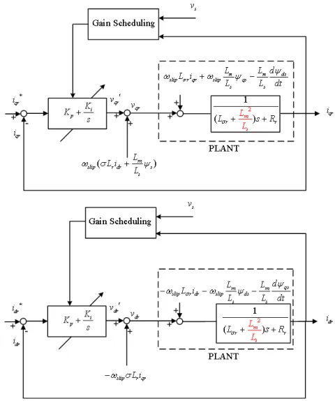
By combining (5) and (23) one can conclude that con-sidering the derivatives of the stator flux linkage in fault conditions, the dynamic model of the DFIG will be mod-ified. As a result, in fault conditions the PI parameters should be altered. Therefore, in our proposed method two sets of PI parameters are designed and tuned specif-ically for normal and fault conditions and stored in a look up table. The default PI parameters are for normal operation. On the occurrence of a fault the parameters of PI controller is updated via look-up table. The block diagram of the proposed control scheme is depicted in Fig. 7. The proposed control system can adapt itself to changes of DFIG dynamics and achieve a good dynamic performance in both normal and fault conditions.
A. Normal Operation
Simulations are carried out in PSIM environment to in-vestigate the effects of switching. However, the outputs from PSIM are sent to MATLAB for presenting more clear graphical results. The studied system is a 1.5 MW wind turbine. The wind turbine, gearbox, and DFIG parameters are provided in Appendix. To analyze the dynamic performance and MPPT algorithm for extract-ing the maximum power at any wind speed, the DFIG wind turbine excited by indirect matrix converter in nor-mal operation mode is simulated. The simulation result presented in Fig. 8. To investigate the performance of MPPT algorithm and change of the active power refer-ence, it is assumed the wind turbine moment of inertia to be 10% of its real value for reducing the simulation time. Total simulation time in this part is 3 seconds. Wind speed is considered as variable and att= 1.6 s has been reduced to 6 m/s. Speed starts to reduce due to a sharp reduction in turbine mechanical torque as shown in Fig. 8a The stator active power with the reference value is shown in Fig. 8b. One of the advantages of the DFIG wind turbine is the independent control of active and reactive power. Referring to (22) the stator reac-tive power corresponds to d-axis component of the rotor current. Fig. 8c shows the d-axis component of the ro-tor current with its reference value. Att = 1 s reactive power reference value is changed to 0.6 pu and att= 2 s is set to zero. Fig. 8c shows that the d-axis component of the rotor current well tracks the reference value and
FIG. 7. Block diagram of proposed control scheme simulation results.
controller renders a good dynamic performance in nor-mal operation. The rectifier of indirect matrix converter is controlled so that the input voltage and current are in phase. Fig. 8d shows the stator and rotor currents of phase a. As can be seen from this figure the frequency of the rotor current is proportional to slip and becomes dc-current around synchronous speed.
B. Fault Condition
In this section performance of a DFIG wind turbine is simulated under fault conditions. As was mentioned in sectionIIaccording to FRT standard of Germany, wind turbines must remain connected to grid following occur-rence of grid faults. Moreover, they must also inject re-active power to help the grid for voltage recovery. To simulate the fault condition, att = 0.7 s the grid volt-ages are dropped by 50% for 300 ms as shown in Fig.
(a) (b)
(c) (d)
FIG. 8. Simulation of DFIG wind turbine excited by IMC in normal operation mode: (a)rotor speed, (b)active power,(c) rotor d-axis current and(d)stator and rotor currents.
FIG. 9. Grid voltages.
the threshold value is set to 1.4 pu. When the rotor cur-rent is greater than the threshold value, the crowbar is activated.
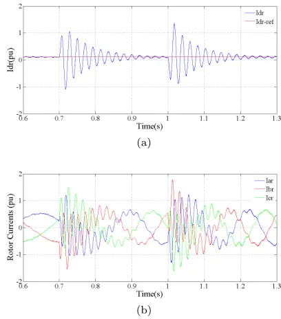
Therefore, as shown in Fig. 11the rotor fault currents are always in the safe operating area of IGBT switches. The proposed adaptive controller, in compare with con-ventional PI controller, provides rapid currents damping. For the studied system the settling time reduces from 200 ms to 100 ms and makes it possible to inject reac-tive power more quickly as required by new FRT stan-dards. Crowbar activation signal presented in Fig. 11c, shows that crowbar will instantly be activated if the ro-tor currents exceed the threshold value. In contrast to conventional PI controller, in the proposed controller the crowbar is active for a shorter time, so for most of the
(a)
(b)
FIG. 10. Rotor currents in fault condition, with the controller designed for normal operation: (a) rotor d-axis current and (b)rotor three phase currents.
(a)
(b)
(c)
FIG. 11. Rotor currents in fault condition, with the proposed method: (a)rotor d-axis current,(b)rotor three phase cur-rents and(c)crowbar activation signal.
pu, respectively. As can be seen from Fig. 11, injection of 1.0 pu reactive current is realized in comply with FRT standard.
VI. CONCLUSIONS
To enhance the LVRT capability of DFIG wind turbines based on indirect matrix converters (IMCs), in this paper a new method is proposed. This method consists of an adaptive gain scheduling controller instead of conventional PI controller. In this approach not only the IMC is protected against large fault currents but the rapid currents damping is also provided. The activation time of crowbar is considerably reduced so, the control system can be in operation most of the fault duration. Therefore, the immediate reactive power injection is
realized to help voltage recovery in order to satisfy the new FRT standards. Simulation results confirm the efficiency of the proposed method.
APPENDIX
Parameters of the studied system are as follows.
Wind turbine:
Pnom= 1.5M W
Base W ind Speed= 12m/s
M oment of inertia= 1.2 M kg.m2 Gearbox:
n1/n2= 1/100 DFIG:
Pnom= 1.5 M W, Vnom= 690V
fnom= 50Hz, Rs= 10.3mΩ
Rr= 8.28mΩ, Lls= 0.2801mH
Llr= 0.1177mH, Lm= 26.96mH
P = 6, J = 116Kg.m2
REFERENCES
1“World Wind Energy Report 2010,”Report. World Wind
En-ergy Association. [Online]. Available: http://www.wwindea.org, Aprill 2011.
2L. H. Hansen, L. Helle, F. Blaabjerg, E. Ritchie, S. Munk-Nielsen, H. Bindner, P. Sorensen and B. Bak-Jensen, “Conceptual survey of Generators and Power Electronics for Wind Turbines,”Riso National Laboratory, Roskilde, Denmark, December 2001. 3L. Wei and T. A. Lipo, “A novel matrix converter topology with
simple commutation,”Industry Applications Conference, 2001. Thirty-Sixth IAS Annual Meeting. Conference Record of the 2001 IEEE, pp.1749-1754 Sept. 30 2001-Oct. 4 2001.
4G. Michalke, “Variable Speed Wind Turbines- Modeling, Con-trol, and Impact on Power Systems,”PhD Thesis,Riso National Laboratory, 2008.
5Z. Cheng and Y. Gangui, “Study on transient performance of doubly fed induction generator with crowbar during three-phase voltage dips,”2015 9th International Conference on Power Elec-tronics and ECCE Asia (ICPE-ECCE Asia), Seoul, pp. 373-376, 2015.
6S. Yang, T. Zhou, X. Zhen, X. Zhang, R. Shao and L. Chang, “A SCR crowbar commutated with rotor-side converter for doubly fed wind turbines,”2015 IEEE 6th International Symposium on Power Electronics for Distributed Generation Systems (PEDG), Aachen, pp. 1-7, 2015.
8Z. Wei, Z. Peng and H. Yikang, “Analysis of the by-pass resis-tance of an active crowbar for doubly-fed induction generator based wind turbines under grid faults,”Electrical Machines and Systems, 2008. ICEMS 2008. International Conference on, pp. 2316-2321, 17-20 Oct. 2008.
9A. Khajeh and R. Ghazi, “Control of DFIG Wind Turbines Based on Indirect Matrix Converters in Short Circuit Mode to Improve the LVRT Capability,”Advances in Power Electronics, Article ID 157431, 11 pages, 2013.
10B. I. Nss, M. Molinas and T. Undeland, “Laboratory tests of ride through for doubly fed induction generators,”In NWPC, Espoo, Finland, May, 2006.
11G. Tsourakis and C.D. Vournas, “Simulation of low voltage ride through capability of wind turbines with double fed induction generator,”In EWEC, Athens, Greece, March 2006.
12M. A. Chowdhury, A. H. M. Sayem, W. Shen and K. S. Islam, “Robust active disturbance rejection controller design to improve low-voltage ride-through capability of doubly fed induction gen-erator wind farms,”inIET Renewable Power Generation, vol. 9, no. 8, pp. 961-969, 2015.
13Q. Huang, X. Zou, D. Zhu and Y. Kang, “Scaled Current Track-ing Control for Doubly Fed Induction Generator to Ride-Through Serious Grid Faults,”inIEEE Transactions on Power Electron-ics, vol. 31, , no. 3, pp. 2150-2165, March 2016.
14R. Ghazi and A. Khajeh, “GA-Based Optimal LQR Controller to Improve LVRT Capability of DFIG Wind Turbines,”IJEEE, Vol. 9, No. 3, pp. 167-176, 2013.
15F. K. A.Lima, A. Luna, P. Rodriguez, E. H. Watanabe and F. Blaabjerg, “Rotor Voltage Dynamics in the Doubly Fed Induc-tion Generator During Grid Faults,”Power Electronics, IEEE Transactions on, vol. 25, no. 1, pp. 118-130, Jan 2010.
16L. Jiaqi, Q. Wei and R. G. Harley, “Direct transient control of wind turbine driven DFIG for low voltage ride-through,”Power Electronics and Machines in Wind Applications, 2009. PEMWA 2009. IEEE, pp. 1-7, 24-26 June 2009.
17M. R. Rathi and N. Mohan, “A novel robust low voltage and fault ride through for wind turbine application operating in weak grids,”Industrial Electronics Society, 2005. IECON 2005. 31th Annual Conference of IEEE, pp., 6-10 Nov. 2005.
18O. Gomis-Bellmunt, A. Junyent-Ferre, A. Sumper and J. Bergas-Jan, “Ride-Through Control of a Doubly Fed Induction Genera-tor Under Unbalanced Voltage Sags,”Energy Conversion, IEEE Transactions on, vol. 23, no. 4, pp. 1036-1045, Dec. 2008. 19Z. Yi, P. Bauer, J. A. Ferreira and J. Pierik, “Operation of
Grid-Connected DFIG Under Unbalanced Grid Voltage Condi-tion,”Energy Conversion, IEEE Transactions on, vol. 24, no. 1, pp. 240-246, March 2009.
20D. Li and H. Zhang, “A combined protection and control strat-egy to enhance the LVRT capability of a wind turbine driven by DFIG,”Power Electronics for Distributed Generation Systems (PEDG), 2010 2nd IEEE International Symposium on, pp. 703-707, 16-18 June 2010.
21C. Abbey and G. Joos, “Short-term energy storage for wind energy applications,”Industry Applications Conference, 2005. Fourtieth IAS Annual Meeting. Conference Record of the 2005, pp. 2035-2042, 2-6 Oct. 2005.
22C. Abbey, Li. Wei, L. Owatta and G. Joos, “Power Electronic Converter Control Techniques for Improved Low Voltage Ride Through Performance in WTGs,”Power Electronics Specialists Conference, 2006. PESC ’06. 37th IEEE, pp. 1-6, 18-22 June 2006.
23I. Erlich, H. Wrede and C. Feltes, “Dynamic Behavior of
DFIG-Based Wind Turbines during Grid Faults,”Power Conversion Conference - Nagoya, 2007. PCC ’07, pp. 1195-1200, 2-5 April 2007.
24J. Amini, R. Kazemzahed and H. Madadi Kojabadi, “Perfor-mance enhancement of indirect matrix converter based vari-able speed Doubly-Fed induction generator,”Power Electronic&
Drive Systems&Technologies Conference (PEDSTC), 2010 1st, pp. 450-455, 17-18 Feb. 2010.
25E. Reyes, R. Pena, R. Cardenas, J. Clare and P. Wheeler, “Con-trol of a Doubly-fed Induction Generator with an Indirect Ma-trix Converter with changing DC voltage,”Industrial Electronics (ISIE), 2010 IEEE International Symposium on, pp. 1230-1235, 4-7 July 2010.
26D. Wenlang, C. Zhiyong, Z. Liming and Y. Yu, “Research on the performance of low voltage ride-through for doubly fed in-duction generator excited by two-stage matrix converter,”Power Electronics and Motion Control Conference, 2009. IPEMC ’09. IEEE 6th International, pp. 638-643, 17-20 May 2009.
Ahmad Khajeh was born in Zabol, Iran in 1982. He received the B.Eng. degree from Sistan and Baluchestan Universtity, Zahedan, Iran, in 2004, and the M.Eng. and Ph.D. degrees from Amirk-abir University of Technol-ogy and Ferdowsi University of Mashhad, Iran, in 2007 and 2014, all in electrical en-gineering, respectively. Cur-rently, he is an Assistant Professor with the Faculty of Electrical and Computer Engineering, University of Sis-tan and BaluchesSis-tan, Zahedan, Iran. His current re-search interests include power electronics, wind power, adjustable speed drives and photovoltaic system.