Research Article ISSN: 2319-507X Kiran Kaware, IJPRET, 2013; Volume 1(8): 348-355 IJPRET
Available Online At www.ijpret.com
INTERNATIONAL JOURNAL OF PURE AND
APPLIED RESEARCH IN ENGINEERING AND
TECHNOLOGY
A PATH FOR HORIZING YOUR INNOVATIVE WORK
P DELTA EFFECT ON TALL BUILDING
PROF. KIRAN. R. KAWARE1, SAGAR. P. LUNGE2
1. Assistant Professor, Mechanical Engineering Department at Raisoni College of Engineering
& Management, Amravati.
2. M. Tech. Scholar, Civil Engineering Department at Govt. College of Engineering, Amravati.
Accepted Date:
27/02/2013
Publish Date:
01/04/2013
Keywords
P-Delta effect,
Tall building,
Rigid frame system,
Shear wall frame system,
Outrigger belt truss
system
Corresponding Author Mr. Kiran. R. Kaware
Abstract
Structural engineers aim to increase the building height
simultaneously they also want to control the deflection for lateral
load in tall buildings. The rigid frame system, shear wall frame
system, outrigger belt truss system are generally used for reducing
the lateral deflection in tall buildings. The P-Delta effect is the
lateral movement of a storey mass to a deformed position is
generating second order overturning moments. This second order
behaviour has been termed the P-Delta. In this paper the two
dimensional 10 storey tall building frame for rigid frame system,
shear wall frame system and outrigger belt truss frame system is
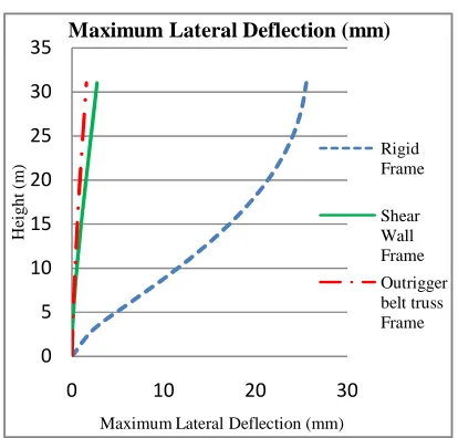
studied for P-Delta effect. It is found that by providing shear wall
frame system maximum lateral deflection reduction is 89.29% with
respect to rigid frame system. It is also found that by providing
outrigger frame system maximum lateral deflection reduction is
Available Online At www.ijpret.com
Introduction:-
The developments and construction of tall
buildings has become need of progress in
India. As per Council of Tall Building and
Urban Habitat (CTBUH) there is no specific
definition of tall building. The criterion of
height selection is totally based on urban
norms. Traditionally the functions of tall
building have been as commercial office
buildings. Scarcity of land led to the other
usages, such as residential, mixed
towers etc. The tall buildings continue to be
built due to their significant economic
benefits in dense urban area.
Due to the great height of these tall
buildings, the lateral forces acting on the
face of building lead to lateral deflection of
building. Control of this lateral deflection is
an issue on which the structural engineers
are concerned now-a-days. It is very
important for structure to have sufficient
strength against vertical loads and
adequate stiffness to resist lateral forces.
There are several structural systems. Out of
these shear wall frame system is one of the
alternative system used for reducing the
lateral deflection. Shear wall frame is
Available Online At www.ijpret.com
The developments and construction of tall
buildings has become need of progress in
Council of Tall Building and
here is no specific
definition of tall building. The criterion of
height selection is totally based on urban
Traditionally the functions of tall
building have been as commercial office
carcity of land led to the other
usages, such as residential, mixed-use, hotel
towers etc. The tall buildings continue to be
built due to their significant economic
Due to the great height of these tall
forces acting on the
face of building lead to lateral deflection of
building. Control of this lateral deflection is
an issue on which the structural engineers
days. It is very
important for structure to have sufficient
vertical loads and
adequate stiffness to resist lateral forces.
There are several structural systems. Out of
these shear wall frame system is one of the
alternative system used for reducing the
lateral deflection. Shear wall frame is
consist of beams, colu
cement concrete wall (shear wall).
Moon [1] describe the history of tall
structural system and technology from 19
century to the current state of
developments. They have given new
guideline for better classification of
structural system as shown in
2.
Fig.1 Interior structures [1]
Fig. 2 Exterior structures [1]
consist of beams, columns and reinforced
cement concrete wall (shear wall). Ali and
Moon [1] describe the history of tall
structural system and technology from 19th
century to the current state of
They have given new
guideline for better classification of
structural system as shown in Fig. 1 and Fig.
Interior structures [1]
Research Article ISSN: 2319-507X Kiran Kaware, IJPRET, 2013; Volume 1(8): 348-355 IJPRET
Available Online At www.ijpret.com
Gunel and Ilgin [2] have studied and briefly
discussed many structural systems that can
be used for the lateral resistance of tall
buildings. They suggested structural system
for different heights of tall building.
Leithy, Hussein and Attia [3] have
investigated the most common structural
systems that are used for reinforced
concrete tall buildings under the action of
gravity and wind loads. Shear wall frame is
combination of shear walls and rigid
frames. It is suited for reinforced concrete
building as well as steel building.
Taranath [4] has described total historical
development in steel, concrete and
composite building from ancient times to
the current state. He has also described the
detailed formulation on the different
structural system.
Sullivan, Pham and Calvi [5] are studied that
45 storey reinforced concrete frame wall for
P delta limit within modal response
spectrum analysis procedure of Eurocode 8.
And found that strength of the structure is
dictated by P delta limit for seismic action.
Moghadam and Aziminejad [6] are studied
that P delta effect in elastic and inelastic
ranges for asymmetric building. Four
building 7, 14, 20 and 30 storey are studied
for with and without P delta effect. It found
that type of lateral load resisting system
plays an important role in degree that
torsion modifies the P delta effect.
Negi [7] gives the recent updated steel
table with all sections and its properties.
From this steel section are uses in this
paper.
SAP 2000v14 [8] manual describes detailed
procedure of modeling, different type of
analysis, results for model. It also described
the P delta effect on building.
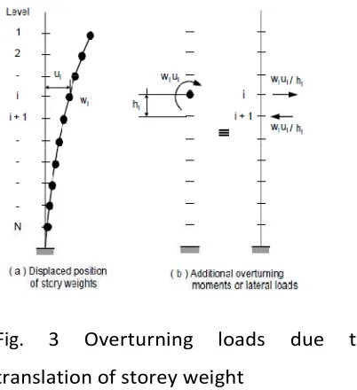
P-delta effect
The P-delta effect is generally occurs on
high rise or tall building. The lateral
movement of a storey mass to a deformed
position is generating second order
overturning moments. This second order
behaviour has been termed the P-Delta.
The additional overturning moments on the
building are equal to the sum of storey
Available Online At www.ijpret.com
displacements. Fig. 3 shows overturning
loads due to translation of storey weight.
Fig. 3 Overturning loads due to
translation of storey weight
The P-delta effect refers specifically to the
nonlinear geometric effect of large tensile
or compressive direct stress upon
transverse bending and shear behaviour. A
compressive stress tends to make a
structural member more flexible in
transverse bending and shear, whereas a
tensile stress tends to stiffer the member
against transverse deformation.
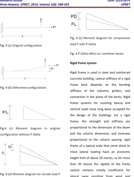
The basic concept behind the P-delta effect
is illustrated in following cantilever beam
example. Consider a cantilever beam
subject to an axial load P and transverse
tip load F as shown in Fig. 4 (a) The
internal axial force through the member is
equal to P. If equilibrium is examined in
the original configuration (using the
undeformed geometry), the moment at the
base is M =FL, and decreases linearly to
zero at the loaded end if, instead,
equilibrium is considered in the deformed
configuration shown in Fig. 4 (b), there is an
additional moment caused by the axial
force P acting on the transverse tip
displacement ∆. The moment no longer
varies linearly along the length; the
variation depends instead upon the
deflected shape. The moment at the base is
now M =FL−P∆ due to tensile load. The
moment at the base is now M =FL+P∆
due to compressive load. Tensile forces
tend to resist the rotation of elements and
stiffen the structure, and compressive
forces tend to enhance the rotation of
elements and destabilize the structure. It
required a moderate amount of iteration.
The moment diagrams for various cases
Research Article ISSN: 2319-507X Kiran Kaware, IJPRET, 2013; Volume 1(8): 348-355 IJPRET
Available Online At www.ijpret.com
Fig. 4 (a) Original configuration
Fig. 4 (b) Deformed configurations
Fig.4 (c) Moment diagram in original
configuration without P-Delta
Fig. 4 (d) Moment diagram for tensile load P
with P-Delta
Fig. 4 (e) Moment diagram for compressive
load P with P-Delta
Fig. 4 P-Delta effect on cantilever beam
Rigid frame system
Rigid frame is used in steel and reinforced
concrete building. Lateral stiffness of a rigid
frame bent depends on the bending
stiffness of the columns, girders, and
connection in the plane of the bents. Rigid
frame systems for resisting lateral and
vertical loads have long been accepted for
the design of the buildings. For a rigid
frame, the strength and stiffness are
proportional to the dimension of the beam
and the column dimension, and inversely
proportional to the column spacing. rigid
frame of a typical scale that serve alone to
resist lateral loading have an economic
height limit of about 30 stories, as for more
than 30 stories the rigidity of the frame
system remains mostly insufficient for
lateral sway resulting from wind and
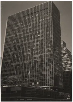
Available Online At www.ijpret.com
House, New York is an example of rigid
frame system.
Fig. 5 Lever house, USA
Outrigger belt truss system
Outrigger belt truss system is modified form
of braced frame and shear walled frame
system. The outrigger belt truss system is
briefly defined as the structural
arrangement consists of main core
connected to the exterior columns by
relative stiff horizontal members commonly
referred to as outrigger. The main core may
consist of a steel braced frame or reinforced
concrete shear walls. The outrigger beam
(girder) may consist of concrete or steel
brace. The outrigger girder is minimum one
floor deep. The belt truss is provided at
outer peripheral of building to reduce the
further deflection [4]. The outrigger belt
truss system is shown in Fig. 9. And building
example of outrigger belt truss system is
Wisconsin Centre in Milwaukee (USA)
shown in Fig. 10 [2].
Fig. 9 Outrigger belt truss system
Research Article ISSN: 2319-507X Kiran Kaware, IJPRET, 2013; Volume 1(8): 348-355 IJPRET
Available Online At www.ijpret.com
Analysis and Result
For two dimensional frame three cases are
studied as follows.
In case First, the two dimensional three
bays of 10 storey tall building frame. The
each bay width is 4 m and storey height is
3.1 m. The frame is fixed at base and total
height of frame is 31 m. The steel column
SC 250 and beam ISLB 250 is provided. The
lateral load of 1 kN/m is applied on left
column (X – direction) only.
In second case, all the data and loading are
same as in first case. The M20 grade of
concrete shear wall having thickness 150
mm is provided in centre bay.
In third case, all the data and loading are
same as in second case. The outrigger beam
ISLB 200 is provided at half height of frame
(i.e. at 15.5 m from base respectively).
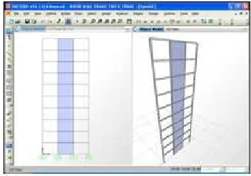
The above three cases are modelled and
analysis in SAP 2000v14 software. The
models for three cases are shown in Fig. 11,
Fig. 12 and Fig. 13. The analysis type is
“Nonlinear static with P delta effect”. The
variation of lateral deflection with height is
shown in Fig. 14.
Fig. 11 Model of two dimensional rigid
frame system
Fig. 12 Model of two dimensional shear
wall frame system
Fig. 13 Model of two dimensional
Available Online At www.ijpret.com
Fig. 14 Lateral deflection with height
References
1. M. M. Ali, and K. S. Moon, “Structural
developments in tall buildings: current
trends and future prospects”, Architectural
Science Review, vol. 50(3), pp. 205-223,
Sept. 2007.
2. H. M. Gunel, and E. H. Ilgin, “Aproposal
for the classification of structural system of
tall buildings”, Building and Environment,
vol. 42, pp. 2667-2675, 2006.
3. N. F. El-Leithy, M. M. Hussein, W. A.
Attia, “ Comparative Study of Structural
Systems for Tall Building”, Journal of
American Science, vol. 7(4), pp. 707-719,
2011.
4. B. S. Taranath, Wind and
EarthquakeRresistant Buildings Structural
Analysis and Design, Marcel Dekker, Los
Angeles California, 1997, ch. 3, pp. 261-348.
5. T. J. Sullivan, T. H. Pham, G. M. Calvi , “
P-Delta Effects on Tall RC Frame-Wall
Buildings” , The 14th World Conference on
Earthquake Engineering, Beijing, China, pp.
12-17, 2008.
6. A.S.Moghadam, A. Aziminejad,
“Interaction of Torsion and P-Delta Effects
in Tall Buildings”, World Conference on
Earthquake Engineering, Vancouver,
Canada, pp. 799-810, 2004.
7. L. S. Negi, Design of Steel Structures, Tata
Mc Graw Hill, New Delhi, 2011, Appendix -
A, pp. 288-305.
8. Structural Analysis Program 2000v14
Manual, Computer and Structures Inc.,
California, USA, 2009.
0 5 10 15 20 25 30 35
0 10 20 30
H
ei
g
h
t
(m
)
Maximum Lateral Deflection (mm) Maximum Lateral Deflection (mm)
Rigid Frame
![Fig.1 Interior structures [1]Interior structures [1]](https://thumb-us.123doks.com/thumbv2/123dok_us/8756861.1750134/2.595.316.492.322.467/fig-interior-structures-interior-structures.webp)