Vol.3 Issue. 5, May- 2015, pg. 9-14
ISSN: 2321-8363
©2015, IJCSMA All Rights Reserved, www.ijcsma.com 9
Routing Protocol for Ad Hoc Network
Based on Location Information
Dr. V.Ramesh
Professor, Department of IT, Mahatma Gandhi Institute of Technology, Hyderabad, India
E-Mail:
[email protected]
Abstract
Geographic routing is a routing principle that relies on geographic position information. Geographic routing protocol employs Boundary State Routing (BSR) with two components namely Greedy-BoundedCompass forwarding and Boundary Mapping Protocol. The main idea behind this routing protocol is that the source sends a message to the geographic location of the destination instead of using the network address. The Greedy-BoundedCompass Forwarding strategy can forward packets around concave boundaries without looping. Boundary Mapping Protocol is used to maintain link state information for boundaries containing concave vertices to route packets around local minima.
Keywords: Wireless LAN, Routing, Routing Algorithm
1.
Introduction
Geographic Routing Protocols typically consist of a primary forwarding strategy and a secondary recovery strategy, which is used when the primary forwarding fails. Here the Boundary State Routing strategy comprises of two components namely Greedy-BoundedCompass forwarding and Boundary Mapping Protocol. In Greedy-BoundedCompass forwarding, Greedy forwarding [5] is used as the primary forwarding strategy and BoundedCompass is used as the fallback strategy on Greedy failure. This Greedy- BoundedCompass forwarding strategy is used to forward packets without looping. But the Greedy-BoundedCompass forwarding fails to forward packets around local minima.
Routing of packets around local minima can be achieved by means of the Boundary Mapping Protocol, which is used to maintain boundary state information for boundaries that contain one or more concave nodes. This Boundary Mapping Protocol (BMP) comprises of two route discovery phases namely, Discovery Phase and Boundary Discovery Phase. Discovery Phase is used to detect voids in the network topology and Boundary Discovery Phase provides boundary information for the boundary members and is made available for routing.
2. Literature Review
Greedy Perimeter Stateless Routing for Wireless Networks (GPSR)
GPSR [2] is a packet-switched routing protocol implementation of GFG using Greedy forwarding and planar graph traversal. Nodes are only required to maintain 1-hop neighbour location information that is exchanged using periodic beacons. Packets are first transmitted with a mode flag set to Greedy. When the local minima is reached, the flag is changed to the perimeter mode, and a face traversal algorithm is used until Greedy forwarding can be resumed. Packets are not permitted to traverse an edge previously traversed to ensure that the packets do not loop. The main drawback of the GPSR is the addition of location registration and lookup traffic for a location database will increase GPSR’s overhead.
2.1 Distance Routing Effect Algorithm for Mobility (DREAM
)
Vol.3 Issue. 5, May- 2015, pg. 9-14
ISSN: 2321-8363
©2015, IJCSMA All Rights Reserved, www.ijcsma.com 10
packets, as opposed to flooding of route requests in LAR, may still incur a significant bandwidth overhead.
2.2 Location-Aided Routing (LAR
)
LAR [4] is an on-demand routing protocol that uses the last known position of the destination node and its velocity to limit the flooding of route requests toward the destination. Flooding is limited to an area between the source and a circle, calculated around the destination, with its centre at the last known position and a radius, which is determined by the node’s velocity. The main drawback of this protocol is scalability and latency associated with on-demand strategies.
3.
Proposed System
Boundary State Routing (BSR) strategy incorporates both the Geographic Forwarding strategy called Greedy-BoundedCompass Forwarding and Geographic Routing strategy called Boundary Mapping Protocol (BMP). Greedy-BoundedCompass Forwarding is a combination of primary Greedy forwarding strategy and a secondary BoundedCompass forwarding strategy, and is used when primary forwarding strategy fails.
Boundary Mapping Protocol (BMP) consists of two phases, which plays a significant role in routing around voids.
Discovery Phase (Helps in void identification)
Boundary Discovery Phase (Provides Boundary State information to route)3.1 Design Representation
3.2 Greedy-BoundedCompass Forwarding
Greedy-BoundedCompass forwarding is an improved forwarding strategy. Initially a packet traverses from the source to the location of destination using Greedy forwarding [5],[6],[7]. According Greedy forwarding the packet from source is forwarded to node which is in closest distance towards the destination. When Greedy forwarding fails, then that location is recorded as Closest Ever Location and the packet switches to BoundedCompass mode. In BoundedCompass mode the packet is traversed until a node or next hop, which is closer than Closest Ever Location to the destination, is found out.
Fig. 1. Overall View of BSR
Greedy-BoundedCompass Forwarding
Boundary Mapping Protocol
Boundary State Routing
Packet forwarding
Without loopingVol.3 Issue. 5, May- 2015, pg. 9-14
ISSN: 2321-8363
©2015, IJCSMA All Rights Reserved, www.ijcsma.com 11
And the mode is reset to Greedy. Then the packet from node which is closer than Closest Ever Location is forwarded to the destination using Greedy forwarding. This component is used to route the packets around convex boundaries.
The route query algorithm for Greedy-BoundedCompass Forwarding is as follows.
Route Query Algorithm
If current node is source Set mode flag to INITIf destination is directly connected neighbour
Update previous ID and previous location in packet to current node ID and location Set mode flag to LINK_STATE
Return destination as next hop
Get next hop using Greedy ()
If next hop == Fail
Get next hop using BoundedCompass ()
If next hop != Fail
Update previous ID and previous location in packet to current node ID and location Return next hop
Algorithm Steps
Step 1:
If the current node is source then set the mode flag to INIT.Step 2:
And if the destination node is directly connected to neighbour to the source then update the previous ID and previous location in packet to current node ID and location. Then set mode to LINK_STATE and return destination as next hop.
Step 3:
Else, Get next hop using Greedy (). And if, next hop is equal to fail then get next hop using BoundedCompass ().Step 4
: Else if, next hop is not equal to fail then, update previous ID and previous location in packet to current node ID and location. Then return next hop.4.
Boundary Mapping Protocol
Boundary Mapping Protocol (BMP) is used to detect void in the network topology and the outer boundary. Boundary Mapping Protocol comprises of two phases namely Discovery Phase and Boundary Discovery Phase. In Discovery phase, any node on a convex vertex initiates a probe packet and transmits the probe packet to the neighbour on a clockwise rotation/anti-clockwise rotation around the vertex by using right-hand/left-hand rule. When the full boundary has been traversed and the packet returns to the source, it will analysis on the probe packet coordinate list and computes angle change. If the angle change equals +360 degrees, then an interior void has detected. Else, if the angle change equals -360 degrees, then an outer boundary has been traversed. Some modification to the boundary traversal rule is used to overcome edge crossovers and branches.
Vol.3 Issue. 5, May- 2015, pg. 9-14
ISSN: 2321-8363
©2015, IJCSMA All Rights Reserved, www.ijcsma.com 12
receives a Discovery probe, then it creates a boundary record and sets its status to Discovery and stores the source node ID of the probe to detect subsequent Discovery probes from the same boundary. If a node is receiving subsequent Discovery probe from the same source then the source node ID in the Discovery probe and Boundary record is compared. And if, the source node ID of Discovery probe is lower than source node ID of the boundary record then the record is updated with the newer source node ID. Else, the probe packet is dropped. When the probe arrives back at source, then the mode is set to Establish and the probe is forwarded around boundary. Each node copies the boundary list into its boundary record and the status is set to Inner Boundary or Outer Boundary.
4.1 BSR Algorithm BSR Route Query
If current node is source Set mode flag to INIT
If destination is directly connected neighbour
Update previous ID and previous location in packet to current node ID and location Set mode flag to LINK_STATE
Return destination as next hop If next hop is available using Greedy ()
Update previous ID and previous location in packet Set mode flag to Greedy
Return next hop
If mode flag != BOUNDARY
If next hop is available using Bounde dCompass () Update previous ID and previous location in packet
If distance from Next Hop to Dest > current node to Dest If alternate next hop is available using Boundary () Set mode flag to Boundary
Return alternate next hop Set mode flag to COMPASS Return next hop
If next hop is available using Boundary () Set mode flag to BOUNDARY
Return next hop
Return FAIL
Algorithm Steps:
Step1
:
If current node is source then set the mode flag to INIT.
Step 2
:
And if the destination is directly connected neighbour update previous ID and previous location in packet. Then set mode to LINK_STATE and return destination as next hop.
Step
3:
If next hop is available using Greedy () then update previous ID and previous location in packet.Vol.3 Issue. 5, May- 2015, pg. 9-14
ISSN: 2321-8363
©2015, IJCSMA All Rights Reserved, www.ijcsma.com 13
Step
4
: If mode flag is not equal to BOUNDARY and if next hop is available using BoundedCompass () then update previous ID and previous location in packet.If distance from next hop to Dest is greater than current node to Dest and if alternate next hop is available using Boundary (). Then set mode flag to BOUNDARY and return alternate next hop. Else, Set mode flag to COMPASS and return next hop.
Step 5
: If next hop is available using Boundary () then set mode flag to BOUNDARY and then return next hop.Else, return FAIL.
5.
R
ESULTS
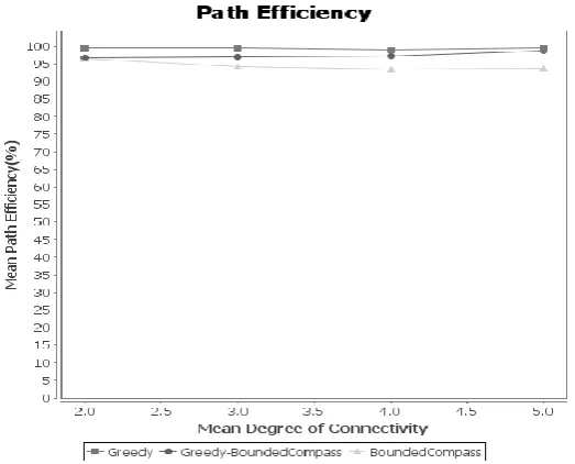
Fig. 2. Comparison between different forwarding strategies for percentage of path completed
Vol.3 Issue. 5, May- 2015, pg. 9-14
ISSN: 2321-8363
©2015, IJCSMA All Rights Reserved, www.ijcsma.com 14
6. Conclusion
An improved forwarding strategy, Greedy-Bounded Compass forwarding is an effective boundary mapping procedure, and a geographic routing protocol BSR, has demonstrated significant improvements in path efficiency. This Greedy-Bounded Compass forwarding has also demonstrated an improved path completion. The BMP maintains the boundary-state information and provides next-hop selection for routing. BMP also minimizes the probing overhead by relying on Greedy with Bounded Compass forwarding to route around convex boundaries.
Future work will improve the boundary selection algorithm to incorporate boundary swapping and pruning of branches before addressing the issues of boundary maintenance and control overhead in mobile topologies.
References
[1].
Colin J. Lemmon and Phillip Musumeci,”Boundary Mapping and Boundary State Routing (BSR) in Ad Hoc Networks,” IEEE TRANSACTIONS ON MOBILE COMPUTING, VOL. 7, NO. 1, JANUARY 2012.[2]. B. Karp and H.T. Kung, “GPSR: Greedy Perimeter Stateless Routing for Wireless Networks,” Proc. ACM MobiCom, pp. 243-254,2010.
[3]. Y.B. Ko and N.H. Vaidya, “Location-Aided Routing (LAR) in Mobile Ad Hoc Networks,” Proc. ACM MobiCom, pp. 66-75, 1998.
[4]. S. Basagni, I. Chlamtac, V.R. Syrotiuk, and B.A. Woodward, “A Distance Routing Effect Algorithm for Mobility (DREAM),” Proc.ACM MobiCom, pp. 76-84, Oct. 1998.
[5]. B.Karp, “Geographic Routing for Wireless Networks.” Harvard Univ., 2000.
[6]. G.Finn,”Routing and Addressing Problems in Large Metropolitan-Scale Internetworks, "Technical Report ISI/RR-87-180, ISI, 1987.