Development of a computer model for long-throated flumes based
on manning equation and different side slopes of trapezoidal
channels
M. Mahbod*1and Sh. Zand-Parsa2
1Department of Water Engineering, College of Agricultural, Jahrom University, Jahrom, I. R. Iran 2Department of Water Engineering, College of Agricultural, Shiraz University, ShirazوI. R. Iran
*Corresponding Author: [email protected] DOI: 10.22099/IAR.2018.4925
ARTICLE INFO
ABSTRACT- Measurement of irrigation water in agricultural areas is necessary, especially, in arid and semi-arid regions. Long-throated flumes have been used to measure irrigation water and are known to be inexpensive devices with high performances. In these structures, head-discharge tables are predicted theoretically with no need to calibrate. In this study, the model of LOTF (LOng Throated Flumes) was developed in VB. net programming language, in which, friction head loss and h-Q (h is head at measuring station and Q is discharge) tables were predicted by using the Manning's equation. The predicted tables of h-Q by the LOTF model were perfectly similar to the results of Win Flume and HEC-RAS model which are universally used for these flumes and open channel flow, respectively. Calculated h-Q tables in trapezoidal flumes with two different side slopes of 0 and 1, 0 and 2, and 0 and 4 were computed by the LOTF and HEC-RAS models and were the same as those predicted by the WinFlume model with equal average of these side slopes of channel. At a water depth, in trapezoidal sections with different and equal average side slopes, the resulted h-Q tables in the three models were the same.
Article history:
Received 26 July 2016 Accepted 5 April 2017
Available online 9 September 2018
Keywords:
Long-throated-flumes Manning's equation Win Flume model LOTF model head-discharge table
INTRODUCTION
Most commonly used structures for measuring flow in open channels operate by producing critical flow or flow at critical–depth through a control section. Under these flow conditions, the discharge through the critical section is a function of the section dimensions and energy at the upstream (energy at measuring station). Flumes such as parshall flumes (Parshall, 1926), cutthroat flumes (Skogerboe et al., 1967) and long-throated flumes (Replogle, 1975) are examples of critical-flow devices. The long-throated flumes and weirs provide cost-effective, practical and flexible capabilities for measuring discharge in open channel systems as used in irrigation channels and these structures are generally very accurate when operated under unsubmerged flow conditions (Keller, 2014). An important component of modern broad-crested weirs and long-throated flumes is the streamlined converging transition. Older broad-crested weirs had either no
became possible to develop theoretical calibrations when it was realized that a suitably gradual transition would simplify the flow condition at the critical section (Wahl et al., 2005). Primary advantages of long-throated flumes include (Wahl et al., 2000, 2005; Sahu et al., 2011; Guan et al., 2014):
Rating table uncertainty of ±2% or better in the computed discharge.
Choice of throat shapes allows a wide range of discharges to be measured with good precision. Minimal head loss needed to maintain critical flow
conditions in the throat of the flume.
Ability to make field modifications and perform computer calibrations using as-built dimensions. Economical to construct, and adaptable to a variety of existing canal configurations.
irrigation schemes in the western part of Kosovo. He suggested that the flow measurement structures for small irrigation schemes should have an easy and solid construction, low maintenance needs, accurate and quick readability of gauges, and a water level drop as small as possible.
For analytical calibrating of long throated flumes, Replogle (1975) developed the principles for prediction of h-Q at measuring station (h is head and Q is discharge) tables. However, development of a h-Q table for a given flume is cumbersome and time-consuming. Hence, computer programs have greatly facilitated the analysis of the structures. The first software was prepared by Replogle (1975) with the purpose of developing rating tables only for trapezoidal and complex trapezoidal shapes and named FLUME. Later on, newer versions of the software have been developed (FLUME 1.0 (Bos et al., 1984); FLUME 2.0 (Clemmens et al., 1987), FLUME 3.0 (Clemmens et al., 1993). Eventually, the last version of the software with the name of WinFlume became available in 2001 (Clemmens et al., 2001). The hydraulic theory used in WinFlume was similar to the FLUME 3.0 program. The model of WinFlume was written entirely in the Visual Basic 4.0 programming language. The program has lots of advantages like: drawing the profile of water surface flow, flume designing, determining limits of discharge for optimal measurements according to downstream and upstream dimensions of channel. In WinFlume, friction head loss from gage section to control section is calculated by using the boundary layer drag coefficient method (Clemmens et al., 2001). Furthermore, in WinFlume, side slopes for the trapezoidal section should be identical.
The HEC-RAS software computes water surface profiles for all channel cross sections (U.S. Army Corps of Engineers., 2005) and universally used for open channel flow. Keller (2014) coupled HEC-RAS with WinFlume for designing long throated flumes. In long-throated flumes, because of producing critical flow in the control section, the HEC-RAS model could be used for preparing h-Q tables in all channel shapes. Jihan (2013) and Jowhar and Jihan (2012) showed that HEC-RAS could predict the flow rating table of the flow over weirs with reasonable accuracy. They showed that HEC-RAS predicted the value of water surface profile with the absolute error between 0.45 and 2.25% with average of 1.45 % of real water surface height.
The contributions of this study are to propose a model (LOTF) to calculateℎ − table based on friction head losses by Manning's equation and considering trapezoidal channels with unequal side slopes. Finally, the results of the proposed model were compared with WinFlume and validated with HEC-RAS software.
MATERIALS AND METHODS
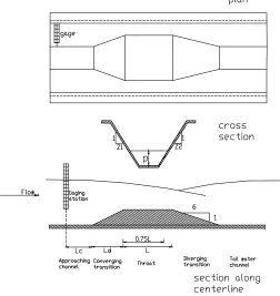
The hydraulic theory for predicting discharge through long-throated flume has resulted from over a century of development. Fig. 1 illustrates the Plan, lengthwise profile and a cross section of a long throated-flume. According to Fig. 1, long-throated flumes are divided into five parts as follows: 1. approach channel, 2. converging transition, 3. throat, 4. diverging transition and 5. tailwater channel. Gage is set up at the upstream of flume (Fig. 1). Passing through the gaging station, flow enters the converging channel with increased velocity. Passing through converging channel, the flow enters the throat and critical flow occurs at 0.75 of the throat length. Finally, water flows to tail water channel after leaving the diverging channel.
Win Flume Theory
The control section is the approximate location of critical flow within the throat of the flume. It is not necessary to know precisely where this occurs, because the developed head-flow rate relationship is expressed in terms of the head upstream. With reference to Figure. 1, application of the energy equation yields:
= + 2 (1)
where and are water depth and velocity at the critical section (on the sill), and is the water energy at the gauging section.
To proceed further, the shape of the control section must be known. For a rectangular cross-section, the properties of critical flow are such that:
+ 2 =32 = 3 2
(2)
where q is the flow rate per unit width within the control section and g is acceleration due to gravity.
Substitution of Equation (2) into Equation (1) and expanding yields:
= 32 (3)
from which:
=23 23
(4)
In terms of the width of the control section, bc, Equation (4) is written as:
=23 23
Fig. 1. Plan, profile, and cross section of long-throated flumes
where Q is the total flow rate. The development of Equation (5) has assumed ideal flow conditions – in particular, that there is no energy loss between the location of the upstream head, H1, and the critical control. Secondly, Q is expressed as a function of H, the total energy level, whereas it is much more useful to express Q as a function of the measured upstream head, h. These are taken into account by introducing a discharge coefficient, Cd, and a velocity coefficient, Cv such that
= 23 23 ℎ
(6)
It was shown by Bos et al. (1981) that and are given by:
= 10.006 10.003ℎ (7)
= 1 +2 ℎ
(8)
Equations (5) to (8) can be generalized for non-rectangular cross-sections once the relationship between
rectangular cross-sections, represent the computational heart of the WinFlume program (Keller, 2014).
LOTF Model Theory
Water velocity in the critical section is a function of energy head at upstream. Therefore, the objective is to find out the height of water surface at the gaging station for a particular discharge. The calculation process for a wide variety of discharges is time-consuming; so, the software (LOTF, LOng Throated Flumes) is prepared. The input parameters for this model are Bed width of throat and the channel, side slopes, maximum and minimum discharges, Manning's coefficient, length of throat, converging and diverging channel lengths, and distance from the gaging station to converging transition. At first, critical depth should be calculated in the critical section. Froud number under critical condition is 1; therefore, given the dimensions of throat and flow discharge, critical cross section area (Ac) can
be calculated as follows:
1
3 2
cc c
gA
B
Q
3 2
1
c c cgA
B
Q
F
(10)
The distance between the critical section and the gaging station is divided into several elements of length
ΔXi (i is the number of nodes at the beginning of each
element). At the first point (critical section), depth and velocity of the flow are calculated using Equation (10). Energy gradient between the two nodes (Sfi) can be
calculated using the calculated depth at the i-1 th node and an assumed depth for the next node (
i
) (i.e.; yi-1)from the following equation:
) 3 / 4 ( 2 2 i i i fi
R
v
n
S
(11)where ni is Manning coefficient and
v
i and Ri aremean velocity and hydraulic radius, respectively, between the two nodes. Therefore, the head loss between the i-1 and
i
nodes can be obtained from Equation (12):Δ
H
i=S
fi×
Δ
X
i (12)where
H
i is head loss along
i. So, the value of energy at i th node is calculated using Equation (13):i i i i i
EL
g
v
y
H
2
2
(13)where yiis water depth, and ELiis bed elevation of i th
node.
The value of Yi is computed by the
Newton-Raphson method by defining Feas in Equation (14) and
setting it equal to zero.
Fe=Hi-Hi-1+ΔHi
(14)
where Hi-1is the value of energy at the i-1th node. After
calculating the value of Yi, the value of Yi+1is computed
in a similar manner. This process will continue until the water depth in gaging station is calculated. Finally, for each discharge value, there is a value for water depth in gaging station. According to the values of minimum, maximum and increment of discharge (as defined by the user), the values of the discharges are definable and water heights at gaging station are calculated. Eventually, a rating table is obtained for a flume with specific dimensions and specific limits of discharge.
If the value of energy at the critical section becomes less than the values of energy at the downstream of flume plus eddy losses at the end of diverging transition, the computation process will stop. The energy in downstream of the flume (tailwater energy) can be calculated based on the procedures by Bos and Reinink (1981) and eddy loss through diverging channel can be obtained as follows (Bos and Reinink, 1981):
g v v H c d 2 )
( 2 2
(15)
724 . 1 165 . )] 1 arctan( 59 . 114 log[ m (16)
whereΔHdis head loss of diverging transition, v2and vc
are velocity in tailwater channel and critical velocity in throat, respectively,ξis an expansion energy head loss coefficient and m is the slope of bed of diverging transition.
RESULTS AND DISCUSSION
In the LOTF model, the rating tables (h-Q) of long throated flumes are predicted theoretically. Channel side slopes (z1,z2), bed width (b), sill height (p), length of approaching channel (Le), throat (L), converging
transition (Ld), the values of minimum and maximum
discharges (Qmin, Qmax) and also the value of discharge increment are necessary for running the model. After running the LOTF model with assumed input parameters, the rating table would be obtained.
In trapezoidal channels, for identical values of the side slopes, the results of LOTF and WinFlume models were compared. The values of dimensions of channels and used flumes for models inputs are shown in Table 1. For side slopes of 0, 1 and 2 and discharge values ranging from 0.2 to 150 m3s-1, rating tables were generated. The predicted discharges are similar in HEC-RAS, WinFlume and LOTF models in all the selected sections. The results of predicted discharges with the same values of h in gaging station are compared by WinFlume and LOTF models in Fig. 2.
When cross-section of channel has two different side slopes, the value of water surface width and cross sectional area are calculated by the following equations:
B
i=b+y
i(z
1+z
2)
(17)2 2 1 ) ( 2 1 i i
i by z z y
A (18)
where Z1 and
z
2are side slopes of channel. Foridentical channel side-slopes (
2
2 1 z
z
z ), the water
surface width and cross-sectional area can be obtained
from
by
i
z
y
i2 andb
2
z
y
i, respectively, and they are equal to equations (17) and (18), respectively.Considering the value of Froud number (
3 2 c c gA B
Q ), equal
to one for critical conditions, and the different side
No
z b p Lc Ld L Qmin Qmin
m m-1 --- m --- --- m3s-1
---1 0 0.85 0.8 2 2.5 1.4 0.04 1.17
2 0 1 5 3 2.5 3 0.84 23.84
3 0 1 20 3 2.5 3.2 3.25 107.32
4 1 0.6 0.6 2 2 1 0.11 2.18
5 1 2 1.5 3 4 3 3.04 33.00
6 1 10 1.5 4 5 4.7 10.11 150.00
7 2 0.6 0.6 1 2 1 0.19 3.42
8 2 1.5 1 1.5 3 2.1 0.93 20.75
9 2 5 1.5 4 5 4.2 3.12 127.60
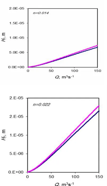
In Fig. 3, the head losses for different side slopes
z1=0, z2=2 and their mean value (Z=1) (
z
1
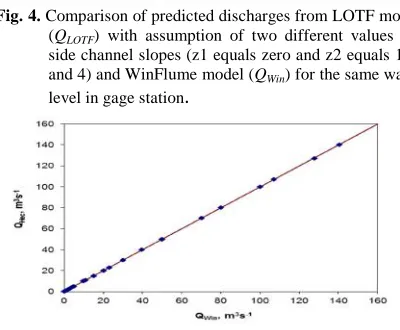
) are compared assuming different Manning's n coefficients (0.014, 0.018, 0.022). As shown in Figure. 3, the head losses, even for high roughness values for both cases of side slopes are very small and the differences are negligible.In Fig. 3, the head losses for different side slopes z1=0, z2=2 and their mean value (z1) are compared assuming different Manning's n coefficients (0.014, 0.018, 0.022). As shown in Figure. 3, the head losses, even for high roughness values for both cases of side slopes are very small and the differences are negligible. For a specific water level in gaging station, the LOTF model with different side slopes and WinFlume with mean value of them provide similar discharges (Fig. 4). This confirms the fact that in a trapezoid channel with different side slopes, their mean value can be used without any error. When the dimensions of selected flumes and channels in Table 1 are used in HEC-RAS model, the predicted h-Q tables are similar to Win Flume model (Fig. 5). So, for all channel sections, the h-Q tables could be predicted by HEC-RAS model, as well
Fig. 3. Comparison of friction head loss in long-throated
flumes from the gaging station to critical section (Hf)
Fig. 4. Comparison of predicted discharges from LOTF model
(QLOTF) with assumption of two different values for
side channel slopes (z1 equals zero and z2 equals 1, 2 and 4) and WinFlume model (QWin) for the same water
level in gage station.
CONCLUSIONS
The results of this research are summarized as follows: The h-Q curves resulted from the LOTF model with friction loss calculated from Manning's equation and those from WinFlume model with friction loss calculated from boundary layer drag coefficient were the same.
The h-Q curve in a channel with two different side slopes could be obtained if the mean value of side slopes is used.
The h-Q curves for all channel sections can also be predicted by using HEC-RAS model.
Finally, further research is needed to compare the results of the LOTF model with experimental data in hydraulic laboratories for channels with different manning coefficient and dimensions.
Fig. 5. Comparison of predicted discharges from HEC-RAS
(QHec) and WinFlume models with the same water
level in gage station in listed flumes of Table 1.
REFERENCES
Ackers, P., White, W. R., Perkins, J. A., & Harrison, A. J. M. (1978). Weirs and Flumes for Flow Measurement. New York, John Wiley & Sons.
Bos, M., & Reinink G. Y. (1981). Head loss over long-throated flumes. Journal of Irrigation and Drainage Division, 107, 87-102.
Bos, M. G., Replogle, J. A., & Clemmens, A. J. (1984). Flow Measuring Flumes for Open Channel Systems. New York, John Wily and Sons.
Clemmens, A. J., Replogle, J. A., & Bos, M. G. (1987). FLUME : A computer model for estimating flow rates through long-throated measuring flumes, , Agricultural Research Service, U.S. Department of Agriculture, U.S. Government Printing Office, Washington, DC: ASR-57. Clemmens, A. J., Wahl, T. L. Bos, M. G., & Replogle, J. A.
(2001). Water measurement with flumes and weirs. Wageningen: ILRI Publication 58.
Clemmmens, A. J. Bos, M. G., & Replogle, J. A. (1993). Flumes: Design and calibration of long-throated measuring Flumes. Version 3.0. Wageningen: ILRI, Publication 54.
Guan, G., Liu, T., Wang, C., Chen, H., & Yao, X. (2014). Effect of side contraction on long-throated flume calibration. NongyeGongchengXuebao/Transactions of Chinese Society of Agricultural Engineering, 30(13), 1-9.
Jihan, M. Q.(2013). Laboratory and HEC-RAS simulation of a single step weir. ARPN Journal of Engineering and Applied Sciences, 8, 1005-1011.
Jowhar, R. M., & Jihan M. Q.(2012). Comparison of one-dimensional HEC-RAS with two-one-dimensional ADH for flow over trapezoidal profile weirs. Caspian Journal of Applied Sciences Research, 1, 1-12.
Keller, R. (2014) Physical model testing and validation of large long-throated flumes. World Environmental and Water Resources Congress: Water Without Borders, 81, 1312-1321.
Parshall, R. L. (1926). The improved venture flumes. Transaction of American Society Civil Engineers, 89, 841-880.
Raza, A., Latif, M., & Nabi, G. (2007). Fabrication and evaluation of a portable long-throated flume. Irrigation and Drainage, 56, 565-575.
Sahu, M., Khatua, K. K., & Mahapatra, S. S. (2011). A neural network approach for prediction of discharge in straight: compound open channel flow. Flow Measurement and Instrumentation, 22, 438–446.
Skogerboe, G. V., Hyatt, M. L., Anderson, R. K., & Eggleston, K. O. (1967). Design and Calibration of Submerged Open Channel Flow Measurement Structures: Part 3, Cutthroat Flumes. Rep.WG31-4 Utah Water Research Laboratory, Utah State University, Logan U.S. Army Corps of Engineers. (2005). HEC-RAS User Manual. Hydrologic Engineering Center, Davis CA. Van Den Bosch, B. E. (2004). Field experience on the
introduction of flow measurement with flumes in Kosovo. Irrigation and Drainage Systems, 18, 299–313.
Vatankhah, A. R., & Mahdavi, A. (2012). Simplified procedure for design of long-throated flumes and weir. Flow Measurement and Instrumentation, 26, 79-84. Wahl, T. L., Clemmens, A. J., Replogle, J. A., & Bos, M. G.
(2005). Simplified design of flumes and weirs. Irrigation and Drainage, 54(2), 231–247
هﺪﯿﮑﭼ
ﻖﯿﻗد يﺮﯿﮔ هزاﺪﻧا ،ﮏﺸﺧ ﻪﻤﯿﻧ و ﮏﺸﺧ ﻖﻃﺎﻨﻣ رد بآ ﻊﺑﺎﻨﻣ دﻮﺒﻤﮐ ﻪﺑ ﻪﺟﻮﺗ ﺎﺑ ياﺮﺑ .ﺪﺷﺎﺑ ﯽﻣ رادرﻮﺧﺮﺑ يا هﮋﯾو ﺖﯿﻤﻫا زا بآ ﻪﻧﻻدﺎﻋ و ﺐﺳﺎﻨﻣ ﻊﯾزﻮﺗ ﺖﻬﺟ نﺎﯾﺮﺟ راﺪﻘﻣ
ﯽﺑد ﯽﻨﺤﻨﻣ ﻪﯿﻬﺗ ﻪﮑﻨﯾا ﻪﺑ ﻪﺟﻮﺗ ﺎﺑ ،ﺪﻨﻠﺑ ﻮﻠﮔ يﺎﻫ مﻮﻠﻓ رﻮﻈﻨﻣ ﻦﯾا
دراﺪﻧ ﯽﺠﻨﺳاو ﻪﺑ زﺎﯿﻧ ﻞﺷا
ﻢﮐ راﺰﺑا ﮏﯾ ناﻮﻨﻋ ﻪﺑ ﺎﺑ ﯽﻟﺪﻣ ﻪﻌﻟﺎﻄﻣ ﻦﯾا رد .ﺪﻨﺷﺎﺑ ﯽﻣ حﺮﻄﻣ ﻖﯿﻗد دﺮﮐرﺎﮐ ﺎﺑ ﻪﺘﺒﻟا و ﻪﻨﯾﺰﻫ
مﺎﻧ
LOTF (LOng Throated Flumes)
ﯽﺑد لوﺪﺟ ﻪﯿﻬﺗ ﺖﻬﺟ
ﻮﻠﮔ يﺎﻫ مﻮﻠﻓ ياﺮﺑ ﻞﺷا
ﻪﺋارا ،ﺪﻨﺷﺎﺒﻧ نﺎﺴﮑﯾ لﺎﻧﺎﮐ يﺎﻫ هراﻮﯾد ﺐﯿﺷ ﻪﮐ ﯽﻄﯾاﺮﺷ رد ﮓﻨﯿﻧﺎﻣ ﻪﻟدﺎﻌﻣ زا هدﺎﻔﺘﺳا ﺎﺑ ﺪﻨﻠﺑ لوﺪﺟ ﻪﮐ داد نﺎﺸﻧ ﺞﯾﺎﺘﻧ .ﺪﯾدﺮﮔ لﺪﻣ ﻂﺳﻮﺗ هﺪﺷ ﺪﯿﻟﻮﺗ ﻞﺷا ﯽﺑد
LOTF
يﺎﻫ لﺪﻣ ﺞﯾﺎﺘﻧ ﺎﺑ
HEC-RAS
و
WinFlume
و زﺎﺑ يﺎﻫ لﺎﻧﺎﮐ رد ﺐﯿﺗﺮﺗ ﻪﺑ بآ ﺢﻄﺳ خﺮﻤﯿﻧ ﻢﯿﺳﺮﺗ ياﺮﺑ ﻪﮐ
هراﻮﯾد ﻪﮐ ﯽﻄﯾاﺮﺷ رد ﻦﯿﻨﭽﻤﻫ .ﺖﺷاد ﯽﻠﻣﺎﮐ ﻖﺑﺎﻄﺗ ،ﺪﻧدﺮﮔ ﯽﻣ هدﺎﻔﺘﺳا ﺪﻨﻠﺑﻮﻠﮔ يﺎﻫ مﻮﻠﻓ ) ﺎﺑ ﺮﺑاﺮﺑ توﺎﻔﺘﻣ ﺐﯿﺷ ياراد لﺎﻧﺎﮐ يﺎﻫ 0
و 2 ) و ( 0 و 4 لﺪﻣ ﻞﺷا ﯽﺑد ﯽﻨﺤﻨﻣ ،ﺪﻨﺘﺷاد (
LOTF
ﻦﯿﮕﻧﺎﯿﻣ راﺪﻘﻣ ﺎﺑ ﺮﺑاﺮﺑ هراﻮﯾد ﺐﯿﺷ ﻪﮐ ﯽﻄﯾاﺮﺷ رد ﺮﮕﯾد لﺪﻣ ود زا ﻞﺻﺎﺣ ﯽﻨﺤﻨﻣ ﺎﺑ ﺐﯿﺷ ﻦﯿﮕﻧﺎﯿﻣ زا ناﻮﺗ ﯽﻣ ﻪﮐ داد نﺎﺸﻧ ﺞﯾﺎﺘﻧ و ﺪﯾدﺮﮔ ﻪﺴﯾﺎﻘﻣ ﺪﺷﺎﺑ لﺎﻧﺎﮐ فﺮﻃ ود ﺐﯿﺷ
لﺪﻣ رد لﺎﻧﺎﮐ هراﻮﯾد ﺐﯿﺷ ناﻮﻨﻋ ﻪﺑ ﺎﻫ هراﻮﯾد
WinFlume
.دﻮﻤﻧ هدﺎﻔﺘﺳا
ﻪﻟﺎﻘﻣ تﺎﻋﻼﻃا
:ﻪﻟﺎﻘﻣ ﻪﭽﺨﯾرﺎﺗ
:ﺖﻓﺎﯾرد ﺦﯾرﺎﺗ 5
/ 5 / 1395
:شﺮﯾﺬﭘ ﺦﯾرﺎﺗ 16
/ 1 / 1396
:ﯽﺳﺮﺘﺳد ﺦﯾرﺎﺗ 18
/6 / 1397
هژاو :يﺪﯿﻠﮐ يﺎﻫ
ﺪﻨﻠﺑﻮﻠﮔ يﺎﻫ مﻮﻠﻓ ﮓﻨﯿﻧﺎﻣ ﻪﻟدﺎﻌﻣ لﺪﻣ
WinFlume
لﺪﻣ
LOTF
ﻞﺷا ﯽﺑد لوﺪﺟ ) ناﺮﯾا يزروﺎﺸﮐ تﺎﻘﯿﻘﺤﺗ
1397 ( 37 ) 2 ( 9 -16
ﺪﻨﻠﺑﻮﻠﮔ يﺎﻫ مﻮﻠﻓ ﯽﺣاﺮﻃ ياﺮﺑ يﺮﺗﻮﯿﭙﻣﺎﮐ لﺪﻣ ﮏﯾ ﻪﺋارا
لﺎـﻧﺎﮐ رد
ﻪـﻟدﺎﻌﻣ سﺎـﺳا ﺮـﺑ توﺎـﻔﺘﻣ ﺐﯿﺷ ﺎﺑ يﺎﻫ هراﻮﯾد ﺎﺑ يا ﻪﻘﻧزوذ يﺎﻫ
ﮓﻨﯿﻧﺎﻣ
ﺪﺒﻬﻣ يﺪﻬﻣ
*1
ﺎﺳرﺎﭘﺪﻧز خﺮﻫﺎﺷ ،
21
بآ ﯽﺳﺪﻨﻬﻣ و مﻮﻠﻋ هوﺮﮔ ،
مﺮﻬﺟ هﺎﮕﺸﻧاد ،يزروﺎﺸﮐ هﺪﮑﺸﻧاد ،مﺮﻬﺟ ،
.ج ناﺮﯾا .ا
2
هوﺮﮔ ،بآ ﯽﺳﺪﻨﻬﻣ هﺪﮑﺸﻧاد
زروﺎﺸﮐ ي ، هﺎﮕﺸﻧاد ﺷ ﯿ زاﺮ ،زاﺮﯿﺷ ، .ج ناﺮﯾا .ا