Abstract — Optical information media printed on paper use printing materials to absorb visible light. There is a 2D code, which may be encrypted but also can possibly be copied. Hence, we envisage an information medium that cannot possibly be copied and thereby offers high security. At the surface, the normal 2D code is printed. The inner layers consist of 2D codes printed using a variety of materials, which absorb certain distinct wavelengths, to form a multilayered 2D code. Information can be distributed among the 2D codes forming the inner layers of the multiplex. Additionally, error correction at cell level can be introduced.
Keywords — confidentiality, error correction, multilayer,
2D code .
I. NTRODUCTION
HIS paper discusses the advancement of confidentiality by hiding information within an optical information medium based on a paper medium.
A. Background
In optical information media, one-dimensional codes (barcodes) and two-dimensional codes (2D codes) are used as information symbols. Since little data volume can be accommodated, a barcode is applicable when accommodating only identification numbers, such as product numbers. When accommodating comparatively many data, a 2D code is used. The same quantity of data can be printed within a smaller area, so 2D codes have found use in various fields. Moreover, a Web address can be accommodated by a 2D code, making it readable with a mobile cellular telephone. Thus, it is becoming easy for someone to read a 2D code and be guided to a Web site.
B. Motivation
The usual 2D code was developed for ease of reading, like in the abovementioned invocation of a Web site. However, the usual 2D code is not suitable for a use that requires confidentiality, like a credit card transaction. In particular, the usual 2D code is easy to copy, and the fact that the duplicate can be read instead the original is a great defect for such use.
C.Previous Work
In order to prevent reading by a third party, a 2D code that has a secret fill area has been developed [1]. Although this also has an open fill area that can be read as a normal 2D code, the secret fill area can only be read by a unit that possesses the encryption key.
For detecting a manipulation attack and forgery, inserting a digital watermark into a 2D code has been proposed [2]–[5]. Similarly, hiding input data by using steganography has been proposed [6]. Further, embedding data in the 2D code of a multi-stage barcode format by using spectrum spreading has been proposed [7]–[9].
Although a 2D code with the abovementioned secret fill area offers confidentiality and cannot be read by a third party, making a copy of the 2D code is easy. Since it is possible to make a copy that reads like the original, this remains a subject of concern in applications.
A 2D code with a digital watermark inserted can disclose a manipulation attack and forgery at the time of reading, and it can prevent data input. However, the content will probably be accessible to a third party and hence lack confidentiality. D. Our Contribution
This paper considers improvements in confidentiality and copy protection, which are challenges faced by current optical information media. Furthermore, a basic configuration for a 2D code that solves these two problems simultaneously is proposed.
In the present research, a 2D code using ink that absorbs ordinary visible light is printed on the surface of a paper medium. Two or more 2D codes using inks that absorb different wavelengths of the infrared region are printed in a pile as the inner layers at the bottom, and so a multilayer 2D code is formed. A high degree of confidentiality is realized by distributing the information among the 2D codes forming the inner layers of the multiplex. The encoding table used for distributing information plays the role of an encryption key. The number of combinations for an encoding table is immense. In fact, decryption by a round-robin attack is impossible.
Copying a 2D code of such a configuration by using visible light is also impossible, since the inks of the inner layers are penetrated by visible light. Moreover, a third party who does not know the encoding table used for distributing the information cannot restore the original 2D code. Thus, a 2D
Confidentiality of 2D Code using Infrared with
Cell-level Error Correction
Nobuyuki Teraura
1and Kouichi Sakurai
2 1Terrara Code Research Institute , Tokai, Japan
2Information Science and Electrical Enginerring, Kyushu University, Fukuoka, Japan
code that simultaneously affords great confidentiality and copy protection is realizable. This enables its safe employment on theatre tickets, parking stubs, highway toll coupons, betting slips, etc.
E. Comparison with Related Work
In order to embed discriminable information visibly in a 2D code, an encoding of three bits is utilized. The encoding adds 1 bit of visual data to 2 bits of regular data and arranges these in the shape of an L character. A visual check is made of whether the data are correct [10]. An encoding table approach is proposed for encoding the module in the shape of the L character.
In the present research, the virtual 2D code that incorporates an actual data bit is distributed between two or more real 2D codes using an encoding table, and the pixels of the virtual 2D code are distributed as many small bits using an encoding table.
Whereas the related work mentioned above was aimed at the authentication of the 2D code through a visual inspection by a person, the present research is aimed at improvement of confidentiality through encryption by data variance.
F. Related Work on Identification using an Image
Information media and persons can be objects of automatic identifications using image data. As examples of information media that are identified from images there are barcodes and two-dimensional codes. The main aims of identifying a person are to maintain security and perform an authentication of the person. In the case of information media, such as a two-dimensional code, the data memorized according to the rule of the structure is read. However, the approach to identifying a person involves learning an individual characteristic beforehand and judging the degree of similarity to the person by comparing with the learned pattern. On occasions when the similarity is high, the algorithm will judge the person to be authentic. The body trait used for this identification can be a fingerprint [11], an iris [12], [13], the face [14], etc., and is put to practical use. Since these approaches use a biological feature of the person, they are called biometrics.
II.HIDING OPTICAL INFORMATION A. Optical Information Media
Although optical information media were originally conceived for identification of alphanumeric characters, this was difficult with the processing capability in those days. Then, symbols representing characters were conceived for computing devices. Even though interpretation would be difficult for people, a symbol easily discerned by a computing device was conceivable. At a time when the microprocessor unit (MPU) had not quite been invented yet, the blue-eye code was devised. Then, the barcode as shown in Fig. 1 was invented with the advent of the MPU and the appearance of a one-dimensional linear sensor. Based on the class of data
(numbers, letters, symbols, etc.) accommodated in a barcode, various kinds of barcodes have been devised and currently are in practical use. Moreover, these follow an international standard fixed by the ISO/IEC.
4 9 1 2 3 4 5 6 7 8 9 0 4 1234567890 Fig. 1. Examples of EAN-13 [15] and Code 39 [16].
A barcode contains information only in the transverse direction, not in the longitudinal direction. Thus, the lengthwise direction of the symbol functions to provide redundancy. When the central part cannot be read, due to dirt etc., it may be possible to read the upper or lower part instead. However, a large area was needed for printing, and there arose the problem that little data volume was contained. Although the barcode was initially put into practical use by encoding only identification, the need for memorizing a larger volume of data has gradually evolved.
The matrix type and stack type of 2D code, as shown in Figs. 2 and 3,were devised in order to meet that need. These have various characteristics, depending on the specific needs.
Fig. 2. QR code [17] and data matrix [18] as examples of the matrix type.
Fig. 3. PDF417 code [19] as an example of the stack type.
B. Security of 2D Code
The following are important for the security of a 2D code: confidentiality of data, impossibility of copying, and impossibility of forgery. The proposed scheme not only realizes confidentiality and copy protection but also prevents forgery.
C.Improvements in Confidentiality
Decryption at Application Level
The decryption at application level involves a system that performs data encryption with an application, creates a 2D code, and then performs data decryption with an application at the time of reading. Since it becomes impossible for a third party to interpret data without the decryption key, a guarantee of confidentiality is feasible. However, the facility to process both encryption and decryption is needed for every individual application, and there is the disadvantage of complexity.
Decryption at System Level
The decryption at system level involves both a system that performs data encryption with an application and a reader that performs data decryption using the encryption key chosen beforehand. A 2D code is created by the application to memorize the data encryption. This may include not only the case where all the storage areas are encryption data areas but also the case where the usual non-enciphering fill area combines with an encryption fill area. Although encryption with an application is required by this system, there is the advantage that decoding is unnecessary. Moreover, in the case of a non-enciphering fill area, reading as with a normal 2D code is possible. It can be said that decryption at system level enabled users easily to keep data secret from a third party.
D.Copy Protection
It is impossible to prevent copying of common optical information media. This is because the reading unit operates by receiving the waves reflected from the medium and a copying machine receives a reflection in the same way. Hence, for copy protection, a theoretically different system is required.
Incidentally, optical information media are very easy to reproduce. Thus, in the case of application to a credit card, the account number is not easily read by others, but uses of replicas cannot be prevented.
III. PHYSICAL PRINCIPLE
For secure optical information media, prevention of reading and protection from copying are important. Thus, an information hiding method for simultaneously realizing both objectives has been developed.
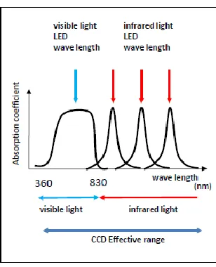
With the usual optical information media, as shown in Fig. 4, a wavelength of the visible light region is used for reading. Conversely, with multilayer optical information media, as shown in Fig. 5, there is a characteristic present so that wavelengths of the infrared light region can be used for reading. On materials that reflect infrared light (e.g., paper), a 2D code is printed using a material that absorbs infrared light as shown in Fig. 6. Therefore, a printed segment and unprinted segment that are irradiated with infrared light become possible to discriminate in a manner similar to that for black and white in visible light. Moreover, different segments can be printed using materials with different peak absorption wavelengths in the infrared light region as shown in Fig. 7. It thus becomes
possible to acquire the image of a 2D code by using a luminous source that matches the absorption wavelength of each layer at the time of reading, even if the code is printed on top of a multilayer.
The 2D code is printed on the surface of the information medium in a material that transmits infrared light but absorbs visible light. Since only a superficial 2D code can be seen when this configuration is irradiated with visible light, it becomes impossible to copy a lower layer.
Fig. 4. Principle for reading an optical information medium.
Fig. 5. Multilayer structure.
Fig. 6. Principle for reading an optical information medium.
IV. PROPOSED SECURITY SYSTEM
As mentioned above, copy protection is realized by the hardware for the information media. In multilayer optical information media with the prescribed structure, the number of layers and the absorption wavelengths of the printing materials are used as the means of confidentiality. The information is memorized by distributing it among two or more layers. The confidentiality of the data is realized by introducing an information variance into the hardware configuration.
Various software approaches to confidentiality may be followed. Here, application of the visual secret sharing scheme is examined. With the visual secret sharing scheme the original image is disassembled into two or more images. Consequently, the image data cannot be identified through human vision unless those images are superposed.
In the decryption of a 2D code, the image (symbol) identification is done by image sensors, so the image editing and identifying capabilities of humans cannot be used. However, since the image sensing capability of an image sensor is greater than that of a human, this identification approach is employed profitably.
A. Encryption and Decoding at Cell Level
A data distribution at cell level is realized by distributing the monochrome data of the original 2D code among the 2D codes of the inner layers. For example, the case of three inner layersshown in Fig. 8 will be examined. The data distribution follows the logical table listed as Table I. Four alternative data encodings are possible for white and black, respectively. These are chosen with a random number.
Fig. 8. Distribution to each layer.
TABLEI CODING TABLE
Even if a third party is able to read all three of the inner layers, decryption is impossible unless the logical table used for the encoding is known. For three inner layers, there are eight merged colors to distribute, from white-white-white to black-black-black, and four of these are chosen for black (or white). The number of encoding tables is 8C4, which becomes 70.
When the number of inner layers, N, is equal to n, the number of hue combinations to distribute, D, is
D = 2n
.
(1)Since the black (white) half is chosen from these combinations, the number of cell encoding tables, TS, is
TS(n) = D
C
D/2 = (2 n)
C
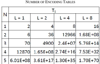
(2n–1). (2) The number of encoding tables for each number of inner layers is listed in Table II. This is introduced here in order to apply several different encoding tables to each cell. The number of different encoding tables is denoted by L.TABLEII
NUMBER OF ENCODING TABLES
Since a layout is chosen with a random number, the inner layers that carry out a cell distribution may become a hue layout that is greatly inclined toward black or white. In that case, since identification of an optical cell becomes difficult, filtering to generate a uniform layout of white and black is needed. However, in the subcell distribution described below, white and black are represented by a subcell that undergoes the same number of occurrences for each, and so this polarization is corrected.
B. Encryption and Decoding at Subcell Level
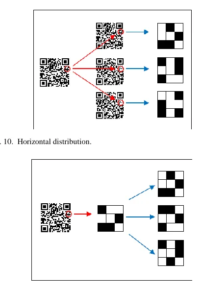
A data distribution (information hiding) at subcell level is realized by dividing a cell into several squares (subcells) and distributing those bits among the subcells of the inner layers as shown in Fig. 9.
There exist both a horizontal manner and a vertical manner for data distribution at subcell level. For a horizontal distribution system as shown in Fig. 10, after first distributing a cell among the cells of an inner layer, the subcells of the same layer are made to redistribute the distributed cell. Conversely, for a vertical distribution system as shown in Fig. 11, after first distributing a cell among virtual subcells, the subcells of the same layer are made to redistribute the distributed subcells.
Fig. 10. Horizontal distribution.
Fig. 11. Vertical distribution.
Here, we argue by using the horizontal manner of distribution for the case in which the number of inner layers is three, and so a cell is decomposed into 3 × 3 subcells. Moreover, in order to employ the same number of white and black subcells, have symmetry, and make identification of a subcell easy, a central subcell is removed from an encoding area and is always considered white. Then, the number of subcells is set to eight. The distribution to the subcells of a cell is performed using the distribution table (encoding table) listed as Table III. This is the same as the case of the previous cell distribution.
TABLEIII CODING TABLE
The number of hue combinations to distribute is 8C4 (i.e., 70). Since these 70 are assigned equally to black and white, the number of bit encoding tables, TB, becomes
TB = 75C35 ≒ 1.12 × 10 20
. (3)
In general, the bit count to distribute is M 2. When the number M 2 is even, the number of hue combinations to distribute, D, becomes
D = (M2)
C
(M2/2), (4)Since these combinations are assigned equally to black and white, the number of bit encoding tables, TB, becomes
TB = D
C
D/2= ((M 2)C(M 2/2))
C
((M 2)C(M 2/2) / 2). (5)Moreover, since a central subcell is eliminated from an encoding area when the number M2 is odd, the number of blacks, B, becomes
B = M2 – 1. (6)
Since the black (white) half is chosen, the number of hue combinations of a subcell, D, becomes
D = BCB/2. (7)
Since these combinations are assigned equally to black and white, the number of encoding tables, TB, becomes
TB = DCD/2. (8)
TABLEIV NUMBER OF ENCODING TABLES
C. Number of Effective Encoding Tables
When the extent of the target 2D code is small and there are few cells, the rule used for the encoding is evident in many of the encoding tables, and so the number of effective encoding tables can be considered to decrease.
If the case of M = 3 is examined, the hue combinations amount to 224. Thus, when the cells exceed this number, the previous argument holds. In the case of a cell size of not more than 15 × 15, if the number of cells is set to j, the number of effective encoding tables becomes jCj/2
V.VERIFICATION OF PROPOSED SECURITY SYSTEM When the number of layers N increases, the number of combinations of cell distributions and subcell distributions (horizontal or vertical) will increase. Here, the number of combinations in the case of the encoding table is examined in the cases of from one to three layers and in the general case of n layers. When the number of inner layers is set to N and the number of subcell distributions is set to M2, the distribution state can be expressed as P(N, M). Below, the number of cases in a distribution is examined using this expression.
A. In the Case of N = 1
Since there is one inner layer in the case of N = 1, there is no distribution to the orientation of an inner layer and only a horizontal subcell variance is possible, as shown in Fig. 12.
Fig. 12. The case N = 1.
If the number of encoding tables for a subcell distribution is set to TB(M), the number of cases becomes
P(1,M) = TB(M). (9)
This is equal to the number of encoding tables for a subcell distribution.
B. In the Case of N = 2
In the case of N = 2 there are two kinds of distributions, as shown in Fig. 13. The first distribution is one in which a horizontal subcell distribution of each cell is carried out after performing a cell variance. The other distribution is one in
which a vertical subcell distribution is carried out.
Fig. 13. The case N = 2.
If the number of cases at the ith subcell of a virtual cell is set to S(k), the total number of cases is obtained as follows:
P(2, M) = S(1) + S(2),
S(1) = TS(2)·TB(M), (10) S(2) = TB(M)·TS(2).
Here, the encoding table of the subcell distribution is assumed identical for each layer. Hereinafter, the same is true.
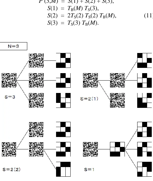
C.In the Case of N = 3
In the case of N = 3 there are four kinds of distributions, as shown in Fig. 14. A characteristic is that not only the horizontal subcell distribution and vertical subcell distribution appear but also the pair in combination.
The number of cases is obtained as follows:
P (3,M) = S(1) + S(2) + S(3), S(1) = TB(M) TS(3),
S(2) = 2TS(2) TS(2) TB(M), (11) S(3) = TS(3) TB(M).
D.In the Case of N = n
The general case of N = n cannot be illustrated like the examples above, but it can be evaluated. If k is the number of virtual cells, the number of cases is obtained as follows:
P(n,M) = Σ S(k)
=
Σ
E(n,k)·TS(k)·TB(M). (13) Here, TS(k) and TB(M) are given by (2) and (4), respectively, while E(n,k) is a coefficient listed in Table V. The number of patterns is determined from the numbers for the case of one fewer layer and the case of one fewer layer with one fewer virtual cell. Therefore, the coefficient obeys the following recurrence formula:E(n, k) = E(n–1, k–1) + E(n–1, k). (14)
TABLEV COEFFICIENT VALUES
VI. CONFIDENTIALITY ESTIMATION
Based on the formula given in the preceding section, the number of calculated encoding tables is listed in Table VI. The subcell distribution table and the table in which the cell encodings differ for each number of inner layers were calculated with the same table.
TABLEVI NUMBER OF ENCODING TABLES
This result means that for N = 1, M = 3, and L = 1, or for N = 3, M = 1, and L = 8, the configuration is easily realized and is effective. Furthermore, the number of cases increases
with an encoding table, so the number of subcell slices, M, is large and confidentiality becomes great. However, a subcell image becomes difficult for a person to read, because its resolution falls. Thus, confidentiality and legibility form the basis of a trade-off in terms of M.
VII. INTRODUCTION OF ERROR CORRECTING CODE The size of the subcells introduced above is comparatively small, and so the possibility of a mistaken reading as a result of dirt or other blemishes on the 2D code is larger than with a regular cell. Accordingly, we now discuss the introduction of an error-correction function for the data in the subcells.
A. Extended Hamming Code
A Hamming code corresponding to the whole number m is constituted with a code length n = 2m – 1 and data length k = n – m. The data length is the bit count of the original data, and the code length is the bit count of the whole code that is generated. Furthermore, an extended Hamming code has a parity bit added, in order to distinguish between 1- and 2-bit errors.
In the case of m = 3, each eight bits consists of four data bits, three error-correction bits, and one parity bit. We now discuss performing error correction using this 8-bit extended Hamming code.
TABLEVII
EXAMPLE OF AN EXTENDED HAMMING CODE
The encoding examples shown in Table VIII correspond to the extended Hamming code shown in Table VII.
TABLEVIII
ENCODING EXAMPLES CORRESPONDING TO AN EXTENDED HAMMING CODE
B. Number of Encoding Tables
In the full encoding list, there are 14 lines (Table VIII gives 8 examples) in which four subcells become of the opposite hue. This is adopted as an encoding bit stream. Therefore, the number of encoding patterns D is
D = 14. (15)
Then, TB becomes
TB = DCD/2 = 14C7
≒ 1.7 × 10⁷. (16)
This value is comparatively small in order to correspond with a round-robin attack. When two encoding tables are used (L = 2), TB becomes
TB≒ 3.0 × 10¹⁴. (17)
This result means that for N = 1, M = 3, and L = 2 the configuration is suitable for introduction of error correction.
VIII.EXAMPLE OF VERTICAL DISTRIBUTION
A detailed image of the 2D code that introduces the error- correction function using the extended Hamming code is shown in Fig. 15. The left-hand side is the 2D code before a data distribution, and the right-hand side is the image after the data distribution. A random number was used when encoding each cell of the original 2D code into subcells.
Fig. 15. Images of 2D code.
IX. CONSIDERATION OF PRACTICAL DIFFICULTIES A. Anti-copying Prerequisites
This paper has discussed the prerequisites that the following three be kept secret: the contents of the inner layers of the 2D code, an infrared wavelength, and the encoding table at the time of data distribution. Therefore, if these pieces of information are known and printing material corresponding to the infrared wavelength is prepared, then creating a replica becomes possible, even though simple copying is impossible.
B. Printing Material and LEDs
The infrared absorption properties of the printing materials now on the market are insufficient to realize multilayer information media [23]. This is because the printing materials now offered have wavelength windows that are wide for absorption of infrared light, so multilayering is not easy. Hence, the development of a marking material with a narrow wavelength window for infrared absorption is expected.
Various LEDs that emit infrared rays have been developed, put on the market, and used for lighting. However, the wavelength range of their infrared light is limited, so infrared LEDs corresponding in wavelength to printing materials still are needed for multilayering.
C.Camera Shake and Focus
In a horizontal distribution, a cell is divided into small subcells and the data are distributed. In order to identify the small subcells, the picturized data need to reveal these as either white or black. However, at the time of image capture, the adjoining subcells of the image may overlap under the effect of camera shake and a clear image may not be obtained. Moreover, identification becomes impossible when the image is not assembled in sharp focus. Camera shake and resultant blurriness that do not pose a concern a cell level may pose a concern at subcell level.
D.Image Resolution
3 × 3 pixels in the identification of a so-called atomic unit. Thus, in the identification of the subcells mentioned above, there will be sufficient image resolution.
X.CONCLUSION
In this paper, multilayer information media using inks that absorb infrared light were introduced, and information media that cannot be copied were proposed. By distributing data among layers, information media with a high degree of confidentiality are realizable. Indeed, the confidentiality has been verified, since combinations of the number of layers and the number of bit distributions that ensure good confidentiality were ascertained.
REFERENCES
[1] M. Hara, “Method for producing 2D code reader for reading the 2D code,” US patent application 20090323959, by Denso Wave Inc., Patent and Trademark Office, 2009.
[2] J.-J. Shen and P.-W. Hsu, “A fragile associative watermarking on 2D barcode for data authentication,” Int. J. Network Security, vol. 7, no. 3, pp. 301–309, Nov. 2008.
[3] L. Li, R.-L. Wang, and C.-C. Chang, “A digital watermark
algorithm for QR code,” Int. J. Intell. Inform. Process., vol. 2, no. 2, pp. 29–36, 2011.
[4] F. Ming, H. Ye, and L. Hong, “A method of 2D BarCode
anti-counterfeit based on the digital watermark,” J. Changsha
Commun. Univ., vol. 24, no. 2, pp. 85–89, 2008.
[5] M. Sun, J. Si, and S. Zhang, “Research on embedding and
extracting methods for digital watermarks applied to QR code images,” New Zealand J. Agric. Res., vol. 50, pp. 861–867, 2007.
[6] W.-Y. Chen and J.-W. Wang, “Nested image steganography
scheme using QR-barcode technique,” Opt. Eng., vol. 48, no. 5, 057004, May 2009.
[7] N. Xiamu, H. Wenjun, W. Di, and Z. Hui, “Information hiding technique based on 2D barcode,” Acta Sci. Natur. Univ. Sunyatseni, vol. 43, pp. 21–25, 2004.
[8] L. Xue, Y. Chao, L. Liu, and X. Zhang, “Information hiding algorithm for PDF417 barcode,” in Proc. 5th Int. Conf. Natural Computation (ICNC ’09), Tianjian, 2009, vol. 6, pp. 578–581.
[9] Z. Bo and H. Jin, “Information hiding technique based on PDF417 barcode,” Comput. Eng. Design, vol. 19, pp. 4806–4809, 2007. [10] C. Fang and E.-C. Chang, “Securing interactive sessions using mobile
device through visual channel and visual inspection,” in Proc. 26th Annu. Computer Security Appl. Conf. (ACSAC ’10), Austin, TX, 2010, pp. 69–78.
[11] M. Jampour, M. M. Javidi, A. S. Nejad, M. Ashourzadeh, and M. Yaghoobi, “A new technique in saving fingerprint with low volume by using chaos game and fractal theory,” Int. J. Interact. Multimed. Artif. Intell., vol. 1, no. 3, pp. 28–32, 2010.
[12] V. L. Hidalgo, L. M. Garcia, and M. T. Lorenzo, “Iris recognition using the JavaVis library,” Int. J. Interact. Multimed. Artif. Intell., vol. 1, no. 1, pp. 43–48, 2008.
[13] M. F. Hurtado, M. H. Langreo, P. M. de Miguel, and V. D. Villanueva, “Biometry, the safe key,” Int. J. Interact. Multimed. Artif. Intell., vol. 1, no. 3, pp. 33–37, 2010.
[14] J. A. Dargham, A. Chekima, and E. G. Moung, “Fusing facial features for face recognition,” Int. J. Interact. Multimed. Artif. Intell., vol. 1, no. 5, pp. 54–60, 2012.
[15] Information technology — Automatic identification and data capture techniques — EAN/UPC bar code symbology specification, ISO/IEC 15420:2009.
[16] Information technology — Automatic identification and data capture techniques — Code39 bar code symbology specification, ISO/IEC 16388:2007.
[17] Information technology — Automatic identification and data capture techniques — QR Code 2005 bar code symbology specification, ISO/IEC 18004:2006.
[18] Information technology — Automatic identification and data capture techniques — Data Matrix bar code symbology specification, ISO/IEC 16022:2006.
[19] Information technology — Automatic identification and data capture techniques — PDF417 barcode symbology specification, ISO/IEC 15438:2006.
[20] R. Villan, S. Voloshynovskiy, O. Koval, and T. Pum, “Multilevel 2D bar codes: Towards high-capacity storage modules for multimedia security and management,” IEEE Trans. Inf. Forens. Security, vol. 1, no. 4, pp. 405–420, 2006.
[21] N. Degara-Quintela and F. Perez-Gonzalez, “Visible encryption: Using paper as a secure channel,” in Proc. SPIE-IS&T Electronic Imaging 2003: Security and Watermarking of Multimedia Contents V, Santa Clara, CA, 2003, vol. 5020, pp. 413–422.
[22] S. Ono, “Fusion of interactive and non-interactive evolutionary computation for two-dimensional barcode decoration,” in Proc. 2010 IEEE Congress on Evolutionary Computation (CEC), Barcelona, 2010, pp. 1–8.
[23] TOSCO Co. Available: http://www.tosco-intl.co.jp/cgibin/imgchemi/ general_display_sensitive.php?id=85&code=SDA5677.
Nobuyuki Teraura received B.S. and M.S. degrees in engineering from the Faculty of Engineering, Nagoya University, Japan. He is a Researcher at the Terrara Code Research Institute, Tokai, Japan. He is also an external PhD student of the Department of Informatics, Kyushu University, Fukuoka, Japan. Mr. Teraura is a member of the IEICE and the Information Processing Society of Japan.
![Fig. 2. QR code [17] and data matrix [18] as examples of the matrix type.](https://thumb-us.123doks.com/thumbv2/123dok_us/9715472.1954859/2.612.317.562.344.464/fig-qr-code-data-matrix-examples-matrix-type.webp)