ORIGINAL ARTICLE
Design and Analysis of a Novel Tension
Control Method for Winding Machine
Xiao‑Ming Xu
1, Wu‑Xiang Zhang
1*, Xi‑Lun Ding
1, Ming Zhang
2and Shi‑Hou Wei
2Abstract
Filament winding has emerged as the main process for carbon fiber reinforced plastic (CFRP) fabrication, and tension control plays a key role in enhancing the quality of the winding products. With the continuous improvement of prod‑ uct quality and efficiency, the precision of the tension control system is constantly improving. In this paper, a novel tension control method is proposed, which can regulate the fiber tension and transport speed of the winding process by governing the outputs of three different driven rollers (the torque of the unwind roll, the torque of the magnetic powder brake roller, and the speed of the master speed roller) in three levels. The mechanical structures and dynamic models of the driven rollers and idle rollers are established by considering the time‑varying features of the roller radius and inertia. Moreover, the influence of parameters and speed variation on fiber tension is investigated using the increment model. Subsequently, the control method is proposed by applying fiber tension in three levels accord‑ ing to the features of the three driven rollers. An adaptive fuzzy controller is designed for tuning the PID parameters online to control the speed of the master speed roller. Simulation is conducted for verifying the performance and sta‑ bility of the proposed tension control method by comparing with those of the conventional PID control method. The result reveals that the proposed method outperforms the conventional method. Finally, an experimental platform is constructed, and the proposed system is applied to a winding machine. The performance and stability of the tension control system are demonstrated via a series of experiments using carbon fiber under different reference speeds and tensions. This paper proposes a novel tension control method to regulate the fiber tension and transport speed. Keywords: Tension control, Control method, Fuzzy logic, Filament winding
© The Author(s) 2018. This article is distributed under the terms of the Creative Commons Attribution 4.0 International License (http://creat iveco mmons .org/licen ses/by/4.0/), which permits unrestricted use, distribution, and reproduction in any medium, provided you give appropriate credit to the original author(s) and the source, provide a link to the Creative Commons license, and indicate if changes were made.
1 Introduction
High modulus carbon fiber is an excellent industrial material, which is widely used in several fields such as satellite supporting cylinder, shells of rocket engine, and solar array. The composite manufacturing process is the key to the application of carbon fiber. Filament winding has emerged as the main process for fabricating com-posite structures. It is widely used in building rotational parts. In the filament winding process, the carbon fiber is delivered from the unwind roll and passed through the resin bath to mix with resin under different temperatures and finally wrap around the surface of the mandrel in the designed pattern. The major specifications that should
be satisfied during the winding process are the winding line type and the fiber tension, which are considered to be the key factors related to the tensile strength of the fiber products. The winding line type is determined using the numerical control system, so this paper focuses on the tension control problem during the winding process. Researchers have shown that unstable tension may lead to loss in strength of fiber winding products [1]. There-fore, fiber tension should be maintained at the reference value during the winding process for ensuring the prod-uct quality.
Several factors shape the tension control design to be challenging, which include significant parameter vari-ations and disturbances. Small varivari-ations in the change of velocity of the transport rollers can cause signifi-cant variations in tension. On the other hand, we used different shapes of mandrels for maintaining the line speed in acceleration or deceleration states. Because
Open Access
*Correspondence: [email protected]
1 School of Mechanical Engineering and Automation, Beihang University,
Beijing 100191, China
of the coupling between the tension and the line speed, it is difficult to maintain the tension at a desired value. Researchers have investigated considerably for acquir-ing better control result. Lee et al. [2] used a magneto rheological brake to provide back tension to prevent fre-quent part changes and fatal malfunction for a tension control system, and a PID controller was designed, and test results showed the feasibility with satisfying the time constant and the allowable error. Nishida et al. [3] divided the transport system into several subsystems and a self-tuning PI controller with an estimator based on a novel adaptive particle swarm optimization method was con-structed to solve the strong coupling between the veloc-ity and tension of the web. A self-tuning PID controller to control the tension for tape winding of composites was designed and the constant extension ratio is guaranteed. To reduce the time required for the stabilization of the tension, a faststabilization method [4] for web tension is proposed. The model of dancer system and stabilization of web tension in drying process are established, and the variation of tension is used as a reference value for the tension stabilization. The integration of load cells and active dancer system for printed electronics applications was used to improve the accuracy of web tension, and self-adapting neural network control was proposed to reduce tension spikes due to the change in roll diameter of winder and unwinder rolls. Wu et al. [5] developed a tension detection and control mechanism and analyzed the main causes of wire tension variation, and then a PI algorithm was proposed to reduce tension variation. An accurate dynamic model for the unwind roll by consider-ing the time variation of the roll inertia and radius was developed, and a decentralized controller for computing the equilibrium inputs for each driven roller was pro-posed [6]. A sliding mode control with guaranteed cost technique [7] was applied for reducing the system uncer-tainties. The simulation results showed that the proposed method had good robustness and quick response time. Compensation method [8] by calculating the torque of a driven loop lifter was developed to control the tension and thickness of hot-rolled strip. For the control strategy, several control methods have been proposed including disturbance rejection control [9–12], neuro-fuzzy control [13–16], and H∞ control [17–19]. Choi et al. [20]
con-ducted a survey on various types of control algorithms by investigating their strengths and weaknesses, and dem-onstrated some areas of potential future development.
Most of the above studies considered the dynamics of driven rollers in the models but the behavior of idle roll-ers was ignored. Consequently, the models were under some limited conditions, which ignored detailed com-plex tension dynamics. On the other hand, most research focused on dynamic modeling and control strategy
design, but the mechanical structure and the influence of parameter variation on fiber tension were ignored. In this paper, a novel tension control method is presented, which can regulate the tension and speed of the filament winding process. The mechanical structure and dynamic model of the system are established, and the influences of the parameter and the speed variation on fiber ten-sion are examined. Subsequently, according to the fea-tures of driven rollers and the influence of variation, the control method is proposed by regulating the outputs of the torque of unwind roll, the torque of magnetic powder brake roller, and the speed of the master speed roller in three levels. Simulations are conducted for verifying the effect by comparing the results with those of the con-ventional PID controller. Finally, the performance of the proposed control system is verified through experimental studies using a filament winding machine.
The structure of the paper is organized as follows. Sec-tion 2 presents the mechanical structure of system. In addition, the dynamic models are constructed, and the influence of parameter and speed variation on the roll-ers is examined. In Section 3, the control strategy is pro-posed. Simulations are conducted for verifying the effect of the proposed controller by comparing with that of the conventional PID controller in Section 4. In Section 5, the proposed mechanical structure and control strategy are applied to a winding machine, and the experimental study is conducted for verifying the performance of the tension control system.
2 Mechanical Structure and Dynamic Modeling
The process line is divided into three zones (Figure 1): the unwind section, the process section, and the rewind section. In each zone, one or two rollers are driven using motors for transporting the carbon fiber from the unwind roll to the rewind roll. The carbon fiber is delivered from the unwind section to the process section, which con-sists of the magnetic powder brake roll, the master speed roller, and some idle rollers. In the process section, the carbon fiber passes through the surface of the master speed roller. As the carbon fiber is comprised of thou-sands of threads, the resin is properly pasted on the sur-face of the carbon fiber. The master speed roller is driven using an AC servomotor, and the speed is controlled for acquiring the desired speed and tension. The rewind sec-tion consists of a four-axis CNC system for acquiring the winding pattern.
master speed roller. In the first level, the unwind roll, which is driven using a torque motor generates a reverse force for applying a pretension to the carbon fiber. The pretension is set at a small value because large tension will cause the tension to deviate from the set point owing to the time-varying radius and the disturbance caused by the periodic swing. In the second level, the magnetic powder brake generates another pretension to the car-bon fiber. The feature of the magnetic powder brake is to generate torque in a wide range without introducing considerable tension interference. However, its disadvan-tage is that the accuracy and response speed are inade-quate than the speed control using the AC servomotor. Finally, in the third level, as the tension is close to the set value, the master speed roller is controlled for acquiring the desired tension. On one hand, the speed of the mas-ter speed roller traces the line speed of the carbon fiber as the reference speed. On the other hand, the speed is adjusted for maintaining tension at a desired value. The response speed is high when the AC servomotor operates in the speed control mode. Consequently, when the line speed of the carbon fiber changes rapidly or in the start-time period, the master speed roller maintains tension in a small range. The control system measures the speed and tension of the carbon fiber, and then controls the
multivariable output of the torque of the unwind roll, the torque of the magnetic powder brake roller, and speed of the master speed roller. The mechanical structure and dynamic modeling of the system is presented as follows.
2.1 Unwind Section
The unwind section consists of an unwind roll and several guide rollers whose function is to release carbon fiber to the process section (Figure 3(a)). The core of the carbon fiber is mounted on the unwind shaft, which is driven using a torque motor. The torque motor applies reverse torque to the unwind roll for generating continuous ten-sion during the transport. During the deceleration stage, as the speed of rewind roll reduces, the carbon fiber will not be firm, resulting in tension discontinuity. The torque motor can solve this by applying reverse torque to maintain the carbon fiber tight and transport tension continuous. As the carbon fiber is delivered to the pro-cess section, the radius of the carbon fiber core becomes smaller. Therefore, the radius and inertia of the unwind roll varies with time. The cross-section view is shown in Figure 3(b), and the dynamics of unwind section is pre-sented as follows.
Unwind Section Process Section Rewind Section
Unwind roll
Magnetic brake
roller Master speed roller Load Cell
v v v
u u
Speed Sensor
Driven Roller Idle Roller
Sensor
Reference
Tension ReferenceTension
Reference Tension -+
Figure 1 Sketch of winding process system
1.Apply small tension 2.Reduce tension deviation due to speed acceleration, change of radius and inertia
1.Apply large tension 2.Not to introduce considerable tension interference Torque motor
Magnetic powder brake
AC servo motor Reference tension
Unwind roll (Level 1)
Magnetic powder brake roller
(Level 2)
Master speed roller (Level 3) Unwind tension
Process tension 1.Regulate tension to acquire reference tension 2.Regulate speed to trace the speed of the carbon fiber
Figure 2 Control method of filament winding process
Torque Motor Carbon Fiber Core
Unwind Shaft Guide Roller
Guide Roller Carbon Fiber
v
a Mechanical structure
the unwind roll
b Cross-section view of
0
U
0
R
0
r
0
v
0
T
The dynamics of the carbon fiber velocity v0 and
ten-sion T0 can be expressed as follows:
where J0(t) is the inertia of the unwind section, U0 is the
input torque from the torque motor, n0 is the gearing
ratio between the torque motor shaft and the unwind roll shaft, ω0 is the angular velocity of the unwind roll and b is
the coefficient of friction.
At any time t, J0(t) consists of three parts:
where Jm is the inertia of the motor shaft, Jc is the inertia
of the unwind roll shaft, both Jm and Jc are constant, Jω(t)
is the inertia of the carbon fiber on the core. As the radius of unwind roll decreases due to the carbon fiber continu-ously releases into the process, Jω(t) is time varying:
where ρ is the density of the carbon fiber, W is the width of the carbon fiber, R0(t) is the radius of the carbon fiber,
r0 is the radius of the carbon fiber core. Therefore, Eq. (1)
can be written as
The rate of change of J0(t) is
Assuming that the thickness of carbon fiber is consid-erably small, the rate of change of radius R0(t) is
approxi-mately expressed as follows:
Equation (4) can be simplified to
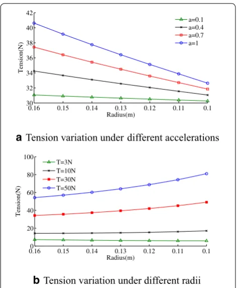
Tension variation under different accelerations and radii was studied in Figure 4.
In Figure 4(a), U0(t)=R0(t)∗30 N , v0=0.5 m/s , a varies from 0.1 to 1 m/s2, and the radius varies from
0.16 to 0.1 m. Larger acceleration causes greater tension deviation from the set value for the same radius. How-ever, in the same acceleration, smaller radius causes smaller tension deviation. In Figure 4(b), U0(t)=0.16T ,
v0=0.5 m/s , a=0.4 m/s2 , and the radius varies from
0.16 to 0.1 m. Tension increases as the radius decreases because the torque is constant. Thus, larger torque causes greater tension deviation.
The longitudinal view of the unwind roll is shown in Figure 5. It is assumed that the carbon fiber on the
(1)
d
dt(J0(t)w0)=T0R0−n 2
0U0−bw0,
(2) J0(t)=Jm+JC+Jω(t),
(3)
Jω(t)=
π
2ρW(R 4 0−r
4 0),
(4) ˙
J0w0+J0ω˙0=T1R0−U0−bw0s.
(5) ˙
J0=2πρw0R30R˙0.
(6) hvdt≈2πR0dR0.
(7)
T0R30=2πρWv0R04R˙0+J0˙v0R0−J0v0R˙0+U0R20+bR0v0.
unwind roll is winded symmetrically, and the screw pitch
δ is constant.
The fiber tension T0 and the tension F on the unwind
roll are related as follows:
The angle θ is associated with the length of the unwind roll L and the distance between the unwind roll and the guide roller s. In general, the diameter of the guide roller is considerably smaller than the length and the distance, so the diameter of the guide roller is ignored. Assuming that l=0,
Consequently, Eq. (7) can be written as follows:
The rate of change of the radius R0 is
(8) Fcosθ =T0.
(9)
cosθ = s
nL− v0t 2πR0δ
2 +s2
.
(10)
T0R30s
nL− 2v0tπR0δ 2
+s2
=2πρWv0R40R˙0+J0v˙0R0
−J0v0R˙0+U0R02+bR0v0.
(11) hvdtδ
L =2πR0dR0,
Tension variation under different accelerations
a
b
Tension variation under different radii0.16 0.15 0.14 0.13 0.12 0.11 0.1
30 32 34 36 38 40 42
Radius(m)
Tension(N)
a=0.1 a=0.4 a=0.7 a=1
0.160 0.15 0.14 0.13 0.12 0.11 0.1 20
40 60 80 100
Radius(m)
Tension(N)
T=3N T=10N T=30N T=50N
The tension can be written as
where l(t)=
nL−2πR(t)vt δ
2 +s2.
As shown in Eq. (13), T0 is associated with angle θ, which
is associated with s and L. The tension variation under dif-ferent relationships between s and L is studied, which is shown in Figure 6. In Figure 6, U0=1.6 N·m , δ=0.02 m , W = 0.01 m, v0=0.5 m/s , a=0.4m/s2 , L = 0.18 m, and s
varies from L to 6L. From Figure 6, we observe that the ten-sion T0 deviates from the set value as the acceleration is not
equal to zero. Moreover, as s increases, the tension fluctua-tion becomes smaller. When s≥4L , the tension fluctua-tion is less than 0.5 N. Therefore, the mechanical structure
(12) ˙
R0= − hv0δ 2πR0L
.
(13) T0= −ρWhδs
Ll v 2 0+
J0hδs
2πR40Ll
v2+ J0s R20l ˙ v+U0s
R0l + sbv0
lR02
,
should be well designed to increase the distance s. So under the condition that s is much larger than L, Eq. (13) can be simplified as Eq. (7) for the control process.
2.2 Magnetic Brake Roller
The magnetic powder brake roller consists of three roll-ers namely, upstream roller, active roller, and downstream roller, as shown in Figure 7, and the active roller is con-nected to a magnetic powder brake for applying the desired tension to the carbon fiber.
The relationship between Ti and Timax+1 is
where Timax+1 is the maximum tension that can be applied on the carbon fiber for preventing it from slipping, µ is
the friction coefficient between the active roller and the carbon fiber, α is the warp angle. In general, µ and α are designed to be significant for achieving high tension.
The dynamic of the active roller can be expressed as follows:
The tension and the velocity dynamic in the active roller are related as follows:
The incremental model of the active roller is
where vri is the reference speed, vqi is the speed increment, Tir is the reference tension, Tiq is the tension increment,
and Uir is the reference torque. In the equilibrium state, (14)
Timax+1/Ti=eµα,
(15) Ji
dwi
dt =(Ti+1−Ti)Ri−nUi−bwi.
(16) Li+1d(Ti+1)
dt =AE(vi+2−vi+1)+Tivi+1−Ti+1vi+2.
(17) Ji(v˙ri + ˙vqi)=(Tir+1+Tiq+1−Tir−Tiq)R
2 i
−nUirRi−b(ωri +ω q i)Ri, Figure 5 Longitudinal section view of unwind roll
0 10 20 30 40 50
8 9 10 11 12 13
Time(s)
Tension(N) s=L
s=2L s=4L s=6L
Figure 6 Tension variation under different s and L
i
v
1
i
v+ i
T Ti+1
2
i
v+
1
i
U+ 1
i
T−
2
i
T+
α
Downstream Roller
Active roller
1
i
L+ Upstream Roller
the increments of the speed and tension are considered to be zero.
Therefore, Eq. (17) can be expressed as follows:
The relationship between Tiq+1 and T q i is
From Eq. (20), we observe that the increment of tension Tiq+1 is smaller with the decrease of Ji and the increase of Ri . Tiq+1 is independent of Ui , which indicates that high
tension Ti+1 can be achieved without introducing
consid-erable tension interference.
2.3 Master Speed Roller
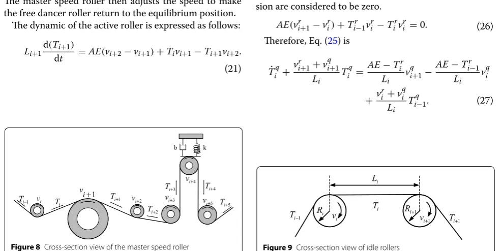
The master speed roller is driven using a servomotor for tracing the speed of the rewind roll and for regulat-ing the tension in a small range, as shown in Figure 8. A passive dancer is used for attenuating the tension and speed disturbances. In the passive dancer mechanism, the dancer roller is free to move on a linear slide, and a spring is mounted between them for increasing the speed response of the dancer mechanism. In the steady state, the free dancer roller is in the equilibrium position and acts as the tension set point. A variation in the speed causes a variation in the tension. Subsequently, the free dancer roller will deviate from the equilibrium position. The master speed roller then adjusts the speed to make the free dancer roller return to the equilibrium position.
The dynamic of the active roller is expressed as follows:
(18)
(Tir+1−Tir)R 2
i −nUirRi−bωirRi−Jiv˙ri =0.
(19) Jiv˙iq=(T
q i+1−T
q i )R
2 i −bω
q i.
(20) Ti+q1=
Jiv˙iq
R2i + bωqi
R2i +T
q i.
(21) Li+1
d(Ti+1)
dt =AE(vi+2−vi+1)+Tivi+1−Ti+1vi+2.
2.4 Idle Roller
The process section consists of a series of idle rollers, and the number of these idle rollers is often considerably large. The effect of idle rollers is usually neglected during steady-state stage such as the acceleration is quite small. But in the case of frequent acceleration and deceleration, dynamic behavior of these idle rollers has a great effect on the fiber tension. The cross-section view of idle roller is shown in Figure 9.
The dynamics of the idle roller is
The dynamic behavior of tension and velocity can be expressed as follows:
In the steady-state stage, as the velocity is constant, Eq. (22) can be written as
Typically, the coefficient of friction b is small and can be ignored. Therefore, in the steady-state process, the idle rollers will not contribute to the dynamic of the sys-tem, which indicates that Ti+1=Ti.
The incremental model of the idle roller is
In the equilibrium state, the increments of speed and ten-sion are considered to be zero.
Therefore, Eq. (25) is
(22) (Ti+1−Ti)Ri+1=J
dwi+1
dt −bwi+1.
(23) Li
d(Ti)
dt =AE(vi+1−vi)+Ti−1vi−Tivi.
(24) (Ti+1−Ti)Ri+1=bwi+1.
(25)
Li(T˙ir+ ˙T q
i )=AE(vir+1+v
q
i+1−vir−v q i)+ (Tir−1+T
q
i−1)(vri +v q
i)−(Tir+1+T
q i)(vri +v
q i).
(26) AE(vri+1−vir)+Ti−1r vir−Tirvri =0.
(27) ˙
Tiq+ v
r i+1+v
q i+1
Li T q i =
AE−Tir Li v
q i+1−
AE−Tir−1
Li v q i
+v
r i +v
q i Li T
q i−1.
i
v vi+1 vi+2 vi+3 4 i v+ 5 i v+ 1 i
T− Ti Ti+1
2
i
T+
3
i
T+ Ti+4
5 i
T+
b k
Figure 8 Cross‑section view of the master speed roller
i L 1 i v+ i T 1 i T+ 1 i R+ i v 1 i
T− Ri
The special solution of Eq. (27) is
Assume that in the start-up stage, vri =vir+1=0 , and the
acceleration ai and ai+1 is constant. Equation (28) is
Typically, AE≫Tir , AE≫Tir−1,
In the acceleration or deceleration stage, when aqi+1>a q i , there is a tension increase when the carbon fiber passes through the idle roller, and there is a tension loss when
aqi+1<a
q i.
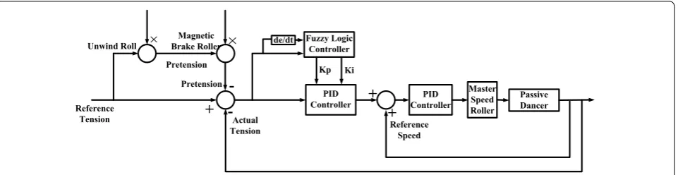
3 Control Method Design
In the unwind section, the acceleration of the transport speed, the change of radius and the swing of carbon fiber along the core can cause tension deviation from the desired value. The pretension of the unwind roll is set at a small value in order to reduce the deviation. In the magnetic powder brake roller, the tension increment is independ-ent of the output torque of the magnetic powder brake, so a large tension can be applied to the carbon fiber. As the tension is close to the desired value, the master speed roller is controlled for acquiring the desired tension and speed. The scheme of tension control is shown in Figure 10. Pre-tensions are applied to the unwind roll and magnetic pow-der brake roller. The tension control of master speed roller consists of two loops: the inner loop is the speed control loop, and the outer loop is the tension control loop. In the
(28) Tiq=e−
vri+1+v
q i+1
Li dt
AE−Tir
Li v
q i+1−
AE−Ti−r 1
Li v
q i +
vri +vqi Li T
q i−1
e vri+1+v
q i+1
Li dtdt.
(29) Tiq= AE−T
r i 2Li
aqi+1t2−AE−T
r i−1
2Li
aqit2+a
q i
Li
Ti−q1tdt.
(30) Tiq≈ AE
2Li
(aqi+1−aqi)t2+a q i Li
Ti−1q tdt.
outer loop, the tension of the load cell is the feedback value, and a controller is designed for regulating the speed cor-rection. In the inner loop, the measured line speed is the reference speed, and the sum of the reference speed and the speed correction is the speed command of the master speed roller. A PID controller is designed for maintaining the master speed roller to trace the speed command.
The PID controller is one of the most widely used regula-tion methods owing to its advantages of strong robustness and simple structure. However, as discussed in Section 2, the dynamic relationship between speed and tension, the time-varying radius and inertia, and the dynamic behavior of the idle rollers are nonlinear and time varying. Therefore, it is difficult to acquire good control effects using the con-ventional PID controller. Fuzzy logic provides a systematic method of incorporating human expertise and implement-ing nonlinear algorithms, which can achieve significant precision and disturbance robustness requirements [13]. Consequently, in order to overcome the problems of sig-nificant parameter variations and disturbances, the fuzzy logic controller is designed to tune the PID parameters online. The adaptive fuzzy controller can be described as follows:
where x(k) includes error e(k) and error change Δe(k), and they are inputs to the fuzzy logic control. K1 and K2 are the input scaling factors of e(k) and Δe(k), respectively.
t(k) is the tension input, and tr(k) is the reference
ten-sion. The output u(k) is �Kp(k) and �Ki(k) , which are the
change in the scaling factor and the derivation time of the PID controller. The output u(k) can be achieved through three stages: fuzzification, decision-making fuzzy logic, and defuzzification.
(31)
x(k)= [e(k)/K1,�e(k)/K2]T,
e(k)=t(k)−tr(k),�e(k)=e(k)−e(k−1),
u(k)= [�Kp(k),�Ki(k)],
Pretension Unwind Roll Pretension Magnetic Brake Roller Reference Tension PID Controller de/dt Fuzzy Logic
Controller Kp Ki Master Speed Roller Passive Dancer Reference Speed PID Controller Actual Tension
-+
-
+
+
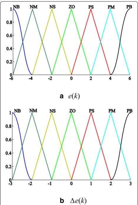
× ×3.1 Fuzzification
The process of fuzzification is characterized by transform-ing the accurate input into a fuzzy set via membership func-tions. The linguistic labels are NB, NM, NS, Z0, PS, PM, and PB. A sigmoid membership function is used when the label is NB and PB, and a triangular membership function is used for other labels. Moreover, the scaling factors are selected by inspecting the operation range. The domains for the varia-bles e(k), �Kp(k) , and �Ki(k) have been normalized to [− 6,
6], and the domain for the variable �e(k) has been
normal-ized to [− 3, 3]. Figure 11 shows the input and output mem-bership functions of the controller.
3.2 Decision‑making Fuzzy Logic
The decision-making process consists of the fuzzy logic rule base and the fuzzy inference engine. The fuzzy logic rule base consists of a series of if–then rules. The rules are extracted from the experiences of skilled human operators. The rule base of �Kp(k) and �Ki(k) are shown
in Tables 1 and 2.
3.3 Defuzzification
The defuzzification process entails a mapping from the space of fuzzy control to a crisp point. In this paper, the center of gravity method is used:
The results of �Kp(k) and �Ki(k) are shown in Figure 12.
4 Simulation
Based on the model presented in Section 2, simulations at different transport speeds and tensions were con-ducted using the conventional PID controller and the proposed fuzzy adaptive controller using MATLAB. One unwind roll, one magnetic powder brake roller, one mas-ter speed roller, and 17 idle rollers were used, and the rewind speed and the reference tension were the input of the system. The radii and inertia of the 17 idle rollers were considered to be the same. The parameters used in the simulation are shown in Table 3. In most tension con-trol systems, the magnetic brake roller is used to regulate the transport tension by a PID controller, and a torque motor applies pretension to keep fiber tight, as shown in Figure 13. The conventional PID algorithm is
The torque of the magnetic brake roller is
(32)
u(k)=Kout
µ(uj)uj
µ(uj)
.
(33) �u(k)=kpe(k)+ki
k
j=0
e(j)T+kd(e(k)−e(k−1))/T.
where ur is the reference torque of the magnetic brake roller.
Simulations of the conventional method and the pro-posed method were conducted to verify the performance of the system.
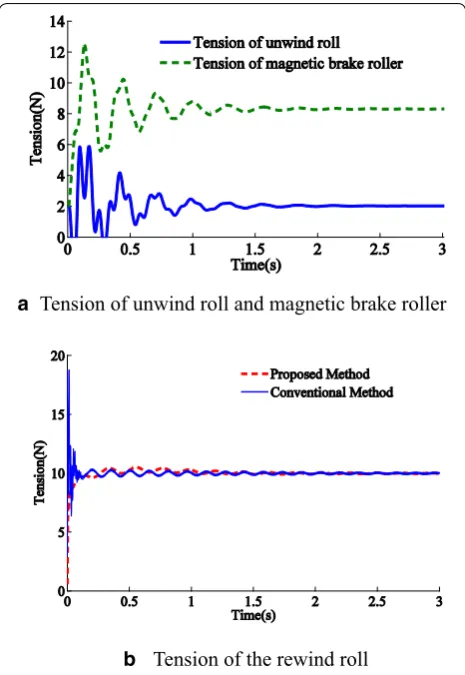
Simulations were run for studying the tension response in the steady-state stage. The reference rewind speed was 60 m/min, and the reference tensions were 10 N, 30 N, and 50 N. Tension of the unwind roll and the magnetic brake roller of the proposed method is shown in Fig-ures 14, 15 and 16(a), the results of conventional method and proposed method are shown in Figures 14, 15 and
16(b). From Figures 14, 15 and 16, we observe that the tension fluctuated around the reference values both in the conventional method and the proposed method owing to two reasons: (1) the interaction due to the speed generates a tension that is vulnerable to the change of the time derivative value of the speed. (2) The periodical swing of the unwind roll generates unstable tension in the
(34) u=ur+�u(k),
a
e
(
k
)
b
∆e
(
k
)
unwind roll. In the proposed method, smaller tension of the unwind roll reduced tension disturbance of the mag-netic brake roller, so the proposed controller provided
faster settling time and lower error than those obtained using the conventional PID controller. The proposed con-troller requires time to finally trace the reference tension, and it requires less time as the reference tension is higher.
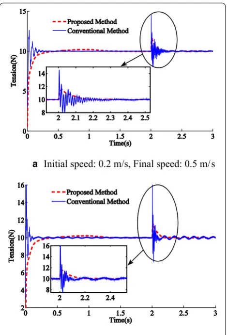
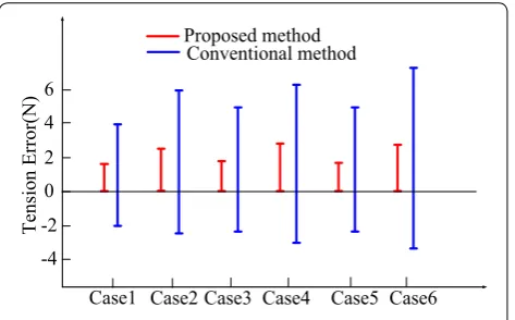
To study the effectiveness of the proposed system in disturbance rejection, a step disturbance in the speed of the rewind roll was introduced at t = 2 s. Simulation results for six cases (Table 4) are shown in Figures 17, 18
and 19.
Table 1 Rule base of �Kp(k)
∆e\e NB NM NS Z0 PS PM PB
NB NB NB NB NB NM NM NS
NM NB NB NB NM NM NS NS
NS NB NM NM NS NS NS Z0
Z0 NM NM NS NS Z0 PS PS
PS NS NS Z0 PS PS PM PM
PM PS PS PM PM PM PB PB
PB PM PM PM PB PB PB PB
Table 2 Rule base of �Ki(k)
∆e\e NB NM NS Z0 PS PM PB
NB NB NB NB NB NB NB NM
NM NB NB NB NB NM NM NM
NS NB NM NS NS NS Z0 Z0
Z0 NS NS Z0 Z0 PS PS PM
PS NS NS Z0 PS PM PM PM
PM PS PS PS PM PM PM PB
PB PM PM PB PB PB PB PB
a Result of ∆Kp(k)
b Result of ∆Ki(k) Figure 12 Results of �Kp(k) and �Ki(k)
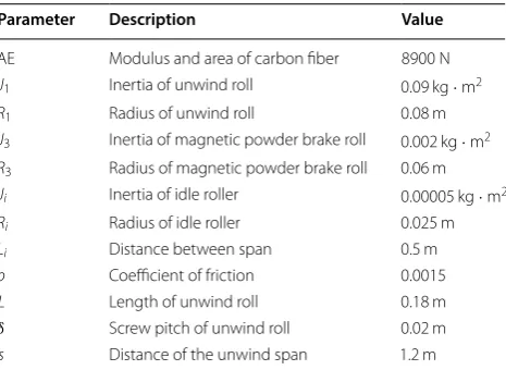
Table 3 Parameters used in simulation
Parameter Description Value
AE Modulus and area of carbon fiber 8900 N J1 Inertia of unwind roll 0.09 kg
·m2
R1 Radius of unwind roll 0.08 m
J3 Inertia of magnetic powder brake roll 0.002 kg ·m2 R3 Radius of magnetic powder brake roll 0.06 m Ji Inertia of idle roller 0.00005 kg·m2
Ri Radius of idle roller 0.025 m
Li Distance between span 0.5 m
b Coefficient of friction 0.0015
L Length of unwind roll 0.18 m
δ Screw pitch of unwind roll 0.02 m
As shown in Figures 17, 18 and 19, a step disturbance in the speed caused an unstable tension, and the peak values of overshoot and undershoot are shown in Fig-ure 20. The proposed controller was capable for reduc-ing overshoot and undershoot of tension caused by the speed disturbance. As the speed disturbance varies from 0.5 m/s to 1 m/s, the peak value of tension error becomes larger.
When the speed varies from 0.5 m/s to 1 m/s at refer-ence tensions 10 N, 30 N, and 50 N for the steady-state error, the conventional PID controller becomes unsta-ble. Moreover, the proposed controller demonstrated a steady performance. The proposed controller provided faster settling time and lower steady-state error, and the
dynamic behavior and accuracy were better than those obtained using the conventional PID controller.
In the filament winding process, different quantities of idle rollers are used owing to different process param-eters. Tension response under different numbers of idle rollers was studied. In Figure 21(a), the reference tension is 30 N, and the speed varies from 0.2 m/s to 0.5 m/s at
t = 2 s. Moreover, in Figure 21(b), the speed varies from 0.5 m/s to 1 m/s at t = 2 s.
As shown in Figure 21, the number of idle rollers influ-ences both the settling time and the overshooting value of the tension. In Figure 21(a), the overshooting value is 2.8 N when N = 21, which is greater than the values 2 N and 2.1 N when N = 14 and N = 17, respectively, and the settling time is slower. In the three cases, the errors e(k) are in the interval [− 2.8, −2] and the linguistic labels are NM and NS. Consequently, the outputs �Kp(k) and
�Ki(k) of the fuzzy control are almost the same, and it
requires more time to reach the equilibrium position in the case N = 21. In Figure 21(b), the overshooting value is 4.6 N when N = 21, which is greater than the value 3.0 N and 2.8 N when N = 14 and N = 17; however, the settling time is faster. The peak error e(k) is −4.6 N, and Unwind Roll
Pretension Reference
Tension
PID
Controller Passive Dancer
Actual Tension
-+
- Magnetic
brake roller
Figure 13 Conventional tension control strategy
a Tension of unwind roll and magnetic brake roller
b Tension of the rewind roll
Figure 14 Tension response for reference tension at 10 N
a
b
Tension of unwind roll and magnetic brake roller
the linguistic labels are NB and NM in the case of N = 21. Compared to the error linguistic labels NM and NS, the outputs �Kp(k) and �Ki(k) of the fuzzy control are
larger, and it requires less time to return to the equilib-rium position.
5 Experiments
5.1 Experimental Platform
Experiments are conducted for verifying the stability and accuracy of the proposed tension control system. A winding machine is constructed for conducting the experiments. As shown in Figure 22, the carbon fiber passes through three driven rollers and 17 other idle rollers from the unwind roll to the rewind roll. In the resin section, the master speed roller is soaked in the resin bath, and with the master speed roller rotation, the resin is attached on the surface of the roll. When carbon fiber passes through the resin, resin and carbon fiber are mixed together. The load cell is mounted near the rewind section, and the speed sensor is also used for measuring the line speed of the carbon fiber.
A DC torque motor that can generate constant torque is used for driving the unwind roll, whereas the master speed roller is driven using an AC servomotor. In the experimental platform, the motors and the magnetic powder brake are driven using dedicated controllers. The torque signals of the magnetic powder brake roller and the unwind roll are generated by using control algorithm software in the host computer. To implement the desired
a
b
Tension of unwind roll and magnetic brake roller
Tension of the rewind roll
0 0.5 1 1.5 2 2.5 3
0 10 20 30 40 50 60 70
Time(s)
Tension(N)
Tension of unwind roll Tension of magnetic brake roller
0 0.5 1 1.5 2 2.5 3
0 10 20 30 40 50 60 70
Time(s)
Tension(N)
Proposed Method Conventional Method
Figure 16 Tension response for reference tension at 50 N
Table 4 Speed and tension parameters Case no. Reference tension
(N) Initial speed (m/s) Final speed (m/s)
1 10 0.2 0.5
2 10 0.5 1
3 30 0.2 0.5
4 30 0.5 1
5 50 0.2 0.5
6 50 0.5 1
a Initial speed: 0.2 m/s, Final speed: 0.5 m/s
b Initial speed: 0.5 m/s, Final speed: 1 m/s
control algorithms, the host computer tunes the PID parameters online and then downloads to the controller. Moreover, the controller calculates the speed and gener-ates speed signal to the motor controller. The scheme of winding machine control system is shown in Figure 23.
In this paper, two different filament winding methods are used: hoop and helical (Figure 24). The method is classified by the angle between the direction of the man-drel rotational axis and the direction in which the carbon fiber is rolled. The hoop winding method is favorable for reinforcing the tensile strength when the angle is 90°. The helical winding method is beneficial for reinforc-ing the strength required for protectreinforc-ing against bendreinforc-ing or twisting forces when the angle is typically 30°, 45°, or 60°. In this paper, the hoop winding method and the heli-cal winding method with an angle of 45° are used. The
Initial speed: 0.2 m/s, Final speed: 0.5 m/s
Initial speed: 0.5 m/s, Final speed: 0.1 m/s
ab
Figure 18 Effect of step disturbance for reference tension at 30 N
a
b
Initial speed: 0.2 m/s, Fina l speed: 0.5 m/s
Initial speed: 0.5 m/s, Final speed: 0.1 m/s
Figure 19 Effect of step disturbance for reference tension at 50 N
0 2 4 6
-2 -4
Proposed method Conventional method
Case1 Case2 Case3 Case4 Case5 Case6
Tension Error(N
)
shapes of the mandrel are rectangular pipe and round pipe. Moreover, the carbon fiber used is M60J, and the tensile modulus is 588 GPa.
5.2 Experimental Results
Extensive experiments at different process parameters, which are mandrel type, reference tension and winding method, are conducted using the proposed tension con-troller. The parameters used in the experiment are shown in Table 5. The reference speed and the actual speed are converted using the master speed roller. The gearing ratio is 27:1, and the diameter of the master speed roller is 300 mm. Experimental results are shown in Figures 25,
26, 27 and 28.
As shown in Figures 25 and 26, in the steady-state stage, the motor speed efficiently traces the reference speed, and the error of tension is regulated to near zero. In Figures 27 and 28, the reference speed changes rapidly, and the disturbance of the speed has significant influence on the tension, the proposed controller can reduce large speed variations to maintain the stability of the system. The proposed controller exhibits excellent performance in terms of tension regulation during the steady-state stage and the acceleration/deceleration stage.
6 Conclusions
(1) In the unwind roll process, the acceleration of the transport speed, the change of radius and the swing of carbon fiber along the core can cause tension deviation from the desired value. Larger
accelera-a
Initial speed: 0.2 m/s, Final speed: 0.5 m/s
b
Initial speed: 0.5 m/s, Final speed: 0.1 m/s
Figure 21 Effect of step disturbance for different numbers of idle rollers
a Unwind and process section b Rewind section
Magnetic brake roller
Master Speed Roller
Load cell
c Process section
Unwind roll Rewind roll
Figure 22 Experimental winding machine
Unwind roll
Torque motor
Motor driver
Master Controller Magnetic brake roller
Magnetic brake
Driver
Master speed roller
Servo motor
Motor driver Load
cell Speed sensor
Host Computer Carbon fiber
Data management Unwind roll
Torque motor
Motor driver
HMI Reference
torque Reference torque Reference torque Masterspeed
Motor speed Fiber tension
Figure 23 Scheme of winding machine control system
Table 5 Parameters used in experiment
Case 1 Case 2 Case 3 Case 4
Mandrel Round pipe Rectangular pipe Round pipe Rectangular pipe
Reference tension (N) 10 11.5 12 12.5
Winding method Hoop Helical Hoop Helical
Torque of unwind roll (N·m) 0.24 0.3 0.32 0.34
Torque of magnetic powder brake roll
(N·m) 0.48 0.54 0.59 0.63
Figure 25 Hoop winding using round pipe, reference tension: 10 N
tion and larger radius cause greater tension devia-tion. The length of unwind roll and the distance between unwind roll and guide roller can cause ten-sion deviation from the set value periodically. (2) In the magnetic powder brake roller, the tension
increment is independent of the output torque of magnetic powder brake. A large tension can be applied to the carbon fiber without introducing considerable tension interference by increasing the radius and decreasing the inertia of the magnetic powder brake roller.
(3) In this paper, a tension control method is proposed by applying tension to the carbon fiber with three dif-ferent driven rollers (the torque of unwind roll, the torque of magnetic powder brake roller, and the speed of master speed roller) in three levels and a fuzzy-PID controller is designed for the speed control of the mas-ter speed roller. Simulation and experimental study show that the proposed method provides faster setting time and lower steady-state error than conventional PID controller in the steady stage and the acceleration stage. The system can stay stable under different refer-ence tensions and transport speeds.
Authors’ Contributions
X‑MX and W‑XZ wrote the manuscript; X‑LD and W‑XZ were in charge of the whole structure of the manuscript; MZ and S‑HW assisted with experimental analysis. All authors read and approved the final manuscript.
Author Details
1 School of Mechanical Engineering and Automation, Beihang University,
Beijing 100191, China. 2 China Academy of Space Technology, Beijing 100094,
China.
Authors’ Information
Xiao‑Ming Xu, born in 1988, is currently a PhD candidate at School of Mechani-cal Engineering and Automation, Beihang University, China. His research interests include design and control of filament winding machine.
Wu‑Xiang Zhang, born in 1978, is currently an associate professor at
School of Mechanical Engineering and Automation, Beihang University, China. He received his PhD degree from Beihang University, China, in 2009. His research interests include the dynamics of compliant mechanical systems and robots, intelligent device and detection technology.
Xi‑Lun Ding, born in 1967, is currently a professor and a PhD candidate supervisor at School of Mechanical Engineering and Automation, Beihang University, China. He received his PhD degree from Harbin Institute of Technol-ogy, China, in 1997. His research interests include the dynamics of compliant mechanical systems and robots, nonholonomic control of space robots, dynamics and control of aerial robots, and biomimetic robots.
Competing Interests
The authors declare that they have no competing interests.
Funding
Supported by National Natural Science Foundation of China (Grant No. 51575018).
Publisher’s Note
Springer Nature remains neutral with regard to jurisdictional claims in pub‑ lished maps and institutional affiliations.
Received: 26 April 2017 Accepted: 27 November 2018
References
[1] P Mertiny, F Ellyin. Influence of the filament winding tension on physical and mechanical properties of reinforced composites. Composites Part A: Applied Science and Manufacturing, 2002, 33(12): 1615–1622.
[2] J H Lee, Y W Yun, H W Hong, et al. Tension control of wire rope in winch spooler using magneto rheological brake. International Journal of Preci-sion Engineering and Manufacturing, 2016, 17(2): 157–162.
[3] T Nishida, T Sakamoto, N I Giannoccaro. Self‑tuning PI control using adaptive PSO of a web transport system with overlapping decentralized control. Electrical Engineering in Japan, 2013, 184(1): 56–65.
[4] S W Jeon, C Kim, C H Kim. Fast stabilization of web tension in drying process of roll‑to‑roll printing equipment for printed electronics. Journal of Mechanical Science and Technology, 2015, 29(12): 5069–5074. [5] Q Wu, Z D Liu, B Zhang, et al. Experimental research on tension balance
control of reciprocating winding diamond wire saw. The International Journal of Advanced Manufacturing Technology, 2017, 91(1–4): 423–431. [6] P R Pagilla, N B Siraskar, R V Dwivedula. Decentralized control of web
processing lines. IEEE Transactions on Control Systems Technology, 2007, 15(1): 106–117.
[7] H W Wang, Y W Jing, C Yu. Guaranteed cost sliding mode control for looper–tension multivariable uncertain systems. Nonlinear Dynamics, 2015, 80(1–2): 39–50.
[8] P V Shilyaev, I Y Andryushin, V V Golovin, et al. Algorithms of a digital automatic system for tension and loop control in a wide‑strip hot‑rolling mill. Russian Electrical Engineering, 2013, 84(10): 533–541.
[9] Y Hou, Z Gao, F Jiang, et al. Active disturbance rejection control for web tension regulation. IEEE Conference on Decision and Control, Orlando, USA, August, 2001: 4974–4979.
[10] S H Liu, X S Mei, F F Kong, et al. A decoupling control algorithm for unwinding tension system based on active disturbance rejection control.
Mathematical Problems in Engineering, 2013, 2013: 1–18.
[11] S H Liu, X S Mei, J Du, et al. Decoupling controller design for unwinding tension system. Journal of Xi’an Jiaotong University Mathematical, 2012, 46(9): 55–59. (in Chinese)
[12] S H Liu, X S Mei, J Li, et al. Design feedforward active disturbance rejec‑ tion control controller for multi‑color register system. Journal of Mechani-cal Engineering, 2015(5): 143–150. (in Chinese)
[13] F Janabi‑Sharifi. A neuro‑fuzzy system for looper tension control in rolling mills. Control Engineering Practice, 2005, 13(1): 1–13.
[14] F Janabi‑Sharifi, J R Liu. Design of a self‑adaptive fuzzy tension controller for tandem rolling. IEEE Transactions on Industrial Electronics, 2005, 52(5): 1428–1438.
[15] G Li, F Janabi‑Sharifi. Fuzzy looperless tension control for hot strip rolling.
Fuzzy Sets and Systems, 2009, 160(4): 521–536.
[16] G Ponniah, M Zubair, Y H Doh, et al. Fuzzy decoupling to reduce propaga‑ tion of tension disturbances in roll‑to‑roll system. The International Journal of Advanced Manufacturing Technology, 2014, 71(1–4): 153–163.
[17] V Gassmann, D Knittel, P R Pagilla, et al. Fixed‑order H∞ tension control in the unwinding section of a web handling system using a pendulum dancer. IEEE Transactions on Control Systems Technology, 2011, 20(1): 173–180.
[18] D Knittel, E Laroche, D Gigan, et al. Tension control for winding systems with two‑degrees‑of‑freedom H∞ controllers. IEEE Transactions on Indus-try Applications, 2003, 39(1): 113–120.
[19] A Benlatreche, D Knittel, E Ostertag. Robust decentralised control strate‑ gies for large‑scale web handling systems. Control Engineering Practice, 2008, 16(6): 736–750.