Vol.8 (2018) No. 1
ISSN: 2088-5334
Static and Dynamic Analysis of Steel U-Damper for Space Structures
Eka Satria
#, Lovely Son
#, Sabril Haris
*, Rahma Saputri
##
Structural Dynamics Laboratory, Dept.of Mechanical Engineering, Andalas University, Kampus Limau Manis, Padang-West Sumatera, 25163, Indonesia
E-mail: [email protected], [email protected], [email protected]
*
Material and Structural Laboratory, Dept.of Civil Engineering, Andalas University, Kampus Limau Manis, Padang-West Sumatera, 25163, Indonesia
E-mail: [email protected]
Abstract—This paper is a part of research in searching an appropriate damper for space structures constructed in seismic areas. The
study investigates a stiffness, strength and energy dissipation of the damper under loading. For this purpose, a U-shaped hysteresis steel damper is modeled and analyzed by a nonlinear finite element technique which involves both geometrical and material nonlinearities. The model is subjected to a monotonic increasing load which is applied horizontally until one cycle of hysteresis is formed. The stiffness, strength, and energy dissipation of the damper is directly determined from the graph of load–displacement. Feasibility of the hysteresis damper is investigated further for application on building construction. The damper is placed on the roof and supporting structure of the building. A 2-DOF spring-mass model, as a simple modelling of the building is introduced with damper’s properties are taken from the results of the first study. A seismic load is applied to see the response of the model. The static numerical analysis showed that the properties of the introduced damper, such as stiffness, strength and energy dissipation, are depending on the geometry of the damper. The results show that reducing the length of lower plate or height of the damper will increase stiffness, strength and energy absorption. In contrary, reducing the width of the damper will decrease all properties. Moreover, the results of the dynamic analysis show the feasibility of damper to reduce to reduce the amplitudes of the response of the roof under seismic load.
Keywords— hysteresis damper; stiffness; strength; energy dissipation; dynamic response; finite element
I. INTRODUCTION
This paper is a part of a series of studies [1]-[5] which are aimed to improve a design method of space structures, particularly in seismic areas. In previous researches, two optimization techniques for improvement of design method had been introduced. First, by applying a form finding technique to steer an initial shape to the final shape whose strength is considered the highest. For example, in Reference [3], three simple plane structures had been introduced with different initial shapes; elliptical, circular and triangular form. Under a static loading, the resulted maximum working stresses are 0.265 kN/cm2 for elliptical shape, 0.024 kN/cm2 for circular shape dan 0.641 kN/cm2 for triangular shape respectively. Through a technique of form finding, the optimal shape can be achieved, and maximum working stress had been successfully reduced to be 0.0316 kN/cm2. It is eight times lower than the maximum working stress of elliptical shape. Moreover, when the strength of the structure is then examined, it shows that the optimal shape is much stronger than all initial shapes. Second, by applying a
member proportioning technique to search an appropriate dimension of the roof’s members. For example, in Ref.[4], a cylindrical roof with the open angle θ0=20 is formed by a
group of steel pipes with diameter dk=311.1 mm and
thickness tk=18.96 mm. Through the application of this
technique, both diameter and thickness can be reduced to dk=282.8 mm dan tk=9.03 mm. These are smaller than the
initial dimensions. It means that the overall weight of the roof had been significantly reduced from 700 kN to 390 kN. It is economically benefit for a construction. Therefore, a combination of both methods (the form finding and the member proportioning) is considerably able to offer a strong and a light space structure.
the structure had been very largely deformed. The reason for this finding is that the occured yielding at the T-joint was able to absorb seismic energy (even until 80% of total energy). It means that the potential damage can be localized to the strut members only, which are uncritical parts of the structure. However, the main problem with the result is that it is actually difficult to assume that the perfect yielding will surely occur in the area of welding without considering the possibility of the welding rack. If the crack takes place, the role of plasticity as an energy absorber cannot be fully conducted. Therefore, this research keeps searching another mechanism which can be acted as a damper and energy absorber at the same time in the process of design of space structures.
Many previous researches were actually conducted related to the models of the energy absorber in buildings. The introduced models were varied, such as pendulum isolator [7], lead rubber bearing [8], viscous damper [9], friction damper [10]. All these models were installed into space structures with a role to reduce the displacement due to seismic load. However, there is still a few studies which is focused on energy dissipation through inelastic deformation in space structures. Reference [11] had proposed a concept of design of roof’s structures supported by substructure with bracing. Yielding of bracing can be used to absorb the energy of the earthquake. The study was then continued by Ref.[12] which used a combination of a viscous-elastic damper and bracing to reduce the displacement of the structures. The newest work related is given in Ref.[13] discussed applying a system of concentrically braced frames (CBF) for tall buildings in seismic areas. Another research [14] proposed a concept of hysteresis damper which was applied in truss system to control damage due to the earthquake. Based on the evaluation, such system is feasible to be applied in long span space structures.
Several researchers have also considered an application of weakened parts as energy absorber to control all possibilities of damage to the main structure under heavy loading. A system, such as reduction of cross-section [15], web opening [16], and wedge [17]. The application of this weakened part is not only in building construction, but it is also widely applied in mechanical or automotive fields [18], [19].
This paper is an initial study to examine the effectiveness of a hysteresis steel damper to be applied in the design of space structures, Unlike the T-joint strut, which is a direct part of the structure, this steel damper is an additional part which is placed between the roof and supporting structure. This paper is aimed to analyze a behaviour of U-shaped hysteresis steel damper under a seismic load. The first part of this paper is to investigate a stiffness, strength and energy dissipation of a hysteresis damper under loading. For this purpose, a hysteresis steel damper is modeled and analyzed by a nonlinear finite element technique which involves both geometrical and material nonlinearities. The monotonic increasing load is horizontally given to the model, then through the application of displacement control method, one cycle of hysteresis is formed. The stiffness, strength, and energy dissipation of the damper is directly taken from the resulted graph of load vs. displacement. The second part is to investigate the feasibility of the hysteresis damper to be applied in building construction. A 2-DOF spring-mass
model, as a simple modelling of the building is introduced with damper’s properties are taken from the results of the first study. A seismic load is then applied to see the response of the model.
II. MATERIAL AND METHOD
In this section, numerical modeling of U-damper, such as geometrical properties and material properties, loading and boundary condition, is described as follows:
A. Geometrical Properties
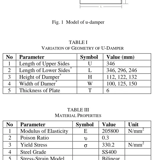
As seen in Fig. 1, a geometrical model of U-damper is introduced, and its dimension is fully described in Table 1.
B. Material Properties
Table 2 shows material properties of U-damper
C. Loading and Boundary Condition
Fig. 2 shows the load and the boundary condition of U-damper under the given load. As seen in the Fig. 2 below, the cyclic load is given in horizontal direction until the deformation reaches 50 mm and then changing the direction of the load.
Fig. 1 Model of u-damper
TABLEI
VARIATION OF GEOMETRY OF U-DAMPER
No Parameter Symbol Value (mm) 1 Length of Upper Sides U 346
2 Length of Lower Sides* L 346, 296, 246 3 Height of Damper* H 112, 122, 132
4 Width of Damer* W 100, 125, 150 5 Thickness of Plate T 6
TABLEIII MATERIAL PROPERTIES
No Parameter Symbol Value Unit 1 Modulus of Elasticity E 205800 N/mm2 2 Poison Ratio υ 0.3
3 Yield Stress σ 330.2 N/mm2
4 Steel Grade SS400
5 Stress-Strain Model Bilinear
Fig. 2 Loading and boundary condition
There are two analysis given in this paper; the first is a static analysis and the second is a dynamic analysis. To conduct the static analysis, a computational program based on a concept of the finite element had been developed to analyze a stiffness and strength of U-damper [10], [20]. This damper is modeled by 20 nodes-hexahedron elements. This program was built by involving nonlinearities of geometry and material. A geometrical nonlinearity is calculated based on Updated Langrangian Jaumann by considering large rotation and displacement, whereas a material nonlinearity is calculated using yield criterion of Von Misses, associated flow rule, and hardening rule. The numerical solution is solved by applying a displacement control method.
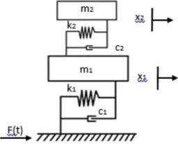
To conduct the dynamic analysis, a simple 2 DOF spring-mass, as seen in Fig. 3 is used to model a low interaction structure and upper structures of the building. The low structure represents the wall and supporting while the upper structure represents the roof of the building.
Fig. 3 Two DOF spring-mass model
Based on the model, the differential equation of motion can be derived as written in Eq.(1).
(1)
where m1 and m2 are mass of supporting structure and roof
structure respectively, c1 and c2 are damping value of
supporting structure and roof structure respectively, k1 and
k2 are stiffness of supporting structure and roof structure
respectively, and f(t) is a seismic load in function of time. As a comparison with a system with no U-damper, the 1 DOF spring-mass model is used with its differential equation of motion is given in Eq.(2). In this equation, the mass of the model is assumed as a sum of mass m1 and m2.
(2)
III. RESULTS AND DISCUSSION
A. Static Analysis
The aim of the static analysis is to get the hysteresis curve of the damper under a cyclic load using an in-house nonlinear finite element computational program. To get one cycle of the hysteresis, a displacement control method is used until the maximum horizontal displacement reaches 50 mm and after that, the direction is reversely changed until -50 mm of displacement. Again, the direction is reversely changed until displacement is back to 50 mm. During calculation, the effect of friction between a plate of the damper and guide frame is neglected.
Seven models are introduced in order to determine the hysteresis curves of the dampers. The models are varied based on three categories of dimension. These are length (L), height (H) and width of the damper (W). Model L1H1W1 is a basic model shows 346 mm of length, 122 mm of height and 125 mm in width. Other six are the variations of the model L1H1W1. Geometries are fully described in Table 3.
TABLEIII GEOMETRIES OF MODEL
No Model L
(mm) H (mm)
W (mm) 1 Model L1H1W1 346 122 125 2 Model L2H1W1 296 122 125 3 Model L3H1W1 246 122 125 4 Model L1H2W1 346 112 125 5 Model L1H3W1 346 132 125 6 Model L1H1W2 346 122 100 7 Model L1H1W3 346 122 150
Through the application of computational program based on finite element method, the hysteresis curves, which show a load-displacement relationship, of all models, are determined as seen in Figs. 4 to 6. From these figures, the elastic stiffness, maximum strength, and energy dissipation of the dampers can be calculated as fully shown in Table 4.
TABLEIV
PROPERTIES OF DAMPER UNDER CYCLIC LOADING
No Model
Elastic Stiffness (N/mm)
Max. Strength (N)
Energy Dissipatio n (N.mm) 1 Model L1H1W1 289.913 6200.4 619.1×10³ 2 Model L2H1W1 332.610 6245.3 703.2×10³ 3 Model L3H1W1 414.293 6281.3 813.4×10³ 4 Model L1H2W1 344.758 6734.1 721.3×10³
5 Model L1H3W1 246.406 5740.7 530.2×10³ 6 Model L1H1W2 230.034 4903.5 491.4×10³ 7 Model L1H1W3 350.390 7517.5 748.2×10³
as well as maximum strength (6281.3 N) than damper with L=296 mm (332.61 N/mm of stiffness and 6245.3 N of strength) and L=346 mm (289.91 N/mm of stiffness and 6200.4 N of strength). Moreover, the total area of load-displacement given by hysteresis curve of L=246 mm is the biggest (813,4×10³ N.mm) compared to L=296 mm (703,2×10³ N.mm) dan L=346 mm (619,1×10³ N.mm). It means that the damper of L=246 mm offers higher energy dissipation than dampers of L=296 mm or L=346 mm.
Fig. 4 Hysteresis curve under variation of lower side’s length of damper
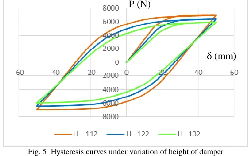
Fig. 5 Hysteresis curves under variation of height of damper
Fig. 6 Hysteresis curves under variation of width of damper
Fig. 5 shows the comparison of hysteresis curves of U-damper under variation of the height of U-damper. Three models are used: L1H1W1 (H=122mm), L1H2W1 (H=112mm) dan L1H3W1 (H=132mm). From the Table 4, it can be clearly seen that reducing the height of damper (from H=132 mm to H=112 mm) increases stiffness as well as the
maximum strength of damper. The elastic stiffness increases from 246.40 N/mm (H=132 mm) to 344.76 N/mm (H=112 mm) and maximum strength also increases from 5740.7 N (H=132 mm) to 6734.1 N (H=112 mm). Moreover, the total area of load-displacement given by hysteresis curve of H=112 mm is the biggest (721.3×10³ N.mm) compared to H=122 mm (619.1×10³ N.mm) dan H=132 mm (530.2×10³ N.mm). It means that shorter height of the damper offers higher energy dissipation than the taller one.
Fig. 6 shows the comparison of hysteresis curves of U-Damper under variation of the width of the damper. Three models are used: L1H1W1 (W=125 mm), L1H1W2 (W=100 mm) dan L1H1W3 (W=150 mm). From the Table 4, it can be clearly seen that increasing the width of the damper (from W=100 mm to W=150 mm) increases stiffness as well as the strength of damper. The elastic stiffness increases from 230.03 N/mm (W=100 mm) to 350.39 (W=150 mm) and maximum strength also increases from 4903.5 N (W=100 mm) to 7517.5 N (W=150 mm). Moreover, the total area of load-displacement given by hysteresis curve of W=150 mm (748.2×10³ N.mm) is the biggest compared to W=100 mm(491.4×10³ N.mm) dan W=125 mm (619.1×10³ N.mm). It means that larger width of the damper offers higher energy dissipation than the smaller ones.
From the Figs. 4 to 6, it can also be seen that the residual plastic deformation of each damper is quite large. It is around 20-30 mm for all models, or around 40-60% of the given maximum displacement (δmax=50 mm). This condition
is not ideal for the damper to act as a damage controller. The yielding initially occurs near the roller supports of the damper (see Fig. 7). The seismic energy will be absorbed by this area through yielding. However, damage to the damper is considered will directly affect the upper structure (roof). Therefore an additional part, which is uncritical, weaker than damper, and able to absorb the energy, needs to be attached to the damper.
Fig. 7 Deformation of u-damper under cyclic load
B. Dynamic Analysis
The aim of the dynamic analysis is to examine the feasibility of the damper to be applied to the building.
As presented in Fig. 1, a simple model of 2 DOF spring-mass is used to represent a modelling of the building. The damper practically is inserted between upper and lower structure of the building. There are several assumptions taken related to the parameters of dynamic of the model, as written below.
• The natural frequencies of mass m1 and mass m2, are
assumed similar, where ω1=ω2=3.14 rad/s
P (N)
δ (mm)
P (N)
• The damping ratio of mass m1 and mass m2 is
assumed as ξ1=0.1 and ξ2=0.01 respectively.
• The stiffness of damper (k2) is calculated from finite
element result (see Table 5).
• Others dynamic parameters are calculated based on Eqs (3) to (7) as follow:
(3)
(4)
(5)
(6)
(7)
Table 5 shows all values of dynamics parameter which are used in the analysis.
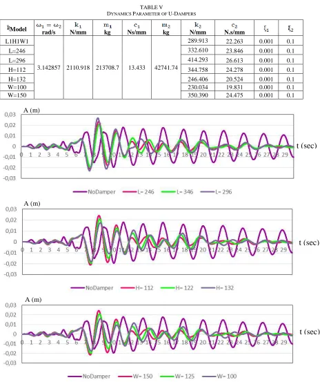
TABLEV
DYNAMICS PARAMETER OF U-DAMPERS
Model rad/s N/mm kg Ns/mm kg N/mm N.s/mm
L1H1W1
3.142857 2110.918 213708.7 13.433 42741.74
289.913 22.263 0.001 0.1
L=246 332.610 23.846 0.001 0.1
L=296 414.293 26.613 0.001 0.1
H=112 344.758 24.278 0.001 0.1
H=132 246.406 20.524 0.001 0.1
W=100 230.034 19.831 0.001 0.1
W=150 350.390 24.475 0.001 0.1
Fig. 8 Comparison of response of upper structures subjected by Kobe earthquake under variation of the length of the lower side of damper (top); under variation of the height of damper (middle); under variation of the width of damper (bottom)
t (sec)
A (m)t (sec)
A (m)A (m)
TABLEVI
DYNAMICS PARAMETER OF U-DAMPERS
Model
rad/s kg N/mm N.s/mm kg N/mm N.s/mm
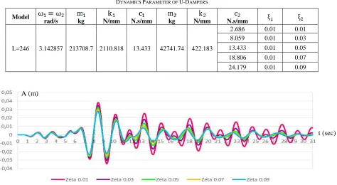
L=246 3.142857 213708.7 2110.818 13.433 42741.74 422.183
2.686 0.01 0.01 8.059 0.01 0.03 13.433 0.01 0.05
18.806 0.01 0.07 24.179 0.01 0.09
Fig. 9 Comparison of response of upper structures under variation of damping values subjected to Kobe earthquake
Fig. 8 shows a comparison of responses of the upper structure due to Kobe’s earthquake with and without using U-Damper under variations of lower side’s length (L), height (H) and width of the damper (W). The result shows that initially, up to 10 seconds, there is no significant effect on structural responses given due to the existence of the damper. However, it changes after 10 seconds, where the amplitude of displacement of the upper structure with damper is getting smaller compared to a non-damper model for all variations of dimension of L, H or W. This indicates the effectiveness of the introduced damper to reduce the displacement of structures under seismic load has been proven.
Fig. 9 shows a comparison of responses of the upper structure due to Kobe’s earthquake with and without using U-damper for a model of L3H1W1 under variation of damping ratios. There are five damping ratios are used in the comparison, those are ξ2=0.01, 0.03, 0.05, 0.07 and 0.09 (see
Table 6). The results show that the damper whose a large damping ratio (i.e. ξ2=0.09) is able to significantly reduce
the amplitude of the response of structure than a small damping ratio (i.e. ξ2=0.01).
IV. CONCLUSION
Several points can be concluded in this paper are as follows:
1) The dimension of the damper significantly affects the elastic stiffness, maximum strength, and energy dissipation of the damper.
• Reducing a lower side’s length of the damper can increase the stiffness, strength and energy dissipation of the damper. For example, the elastic stiffness, maximum strength, and energy dissipation of the
damper with L=346 mm increase from 289.913 N/mm, 6200.4 N and 619.1×10³ N.mm respectively to be 414.293 N/mm, 6281.3 N and 813.4×10³ N.mm respectively if the dimension of L=246 mm.
• Reducing height of the damper can increase the stiffness, strength and energy dissipation of the damper. For example, the elastic stiffness, maximum strength, and energy dissipation of the damper with H=132 mm increase from 246.406 N/mm, 5740.7 N and 530.2×10³ N.mm respectively to be 344.758 N/mm, 6734.1 N and 721.3×10³ N.mm respectively if the dimension of H=112 mm.
• Increasing width of the damper can increase the stiffness, strength and energy dissipation of the damper. For example, the elastic stiffness, maximum strength, and energy dissipation of the damper with W=100 mm increase from 230.034 N/mm, 4903.5 N and 491.4×10³ N.mm respectively to be 350.39 N/mm, 7517.5 N and 748.2×10³ N.mm respectively if the dimension of W=150 mm.
2) The U-damper is feasible to be applied in the design of space structures due to its ability to reduce the maximum amplitude of structural response during an earthquake. The result shows that even using a small damping ratio of the roof, for example ξ2=0.01, the U-Damper is still able to
reduce the maximum amplitude of structural responses. Moreover, increasing of a damping ratio, for example until
ξ2=0.09, emphasized the effectiveness of damper in reducing
the structural responses due to the earthquake.
3) However, the U-damper cannot be considered able to act as a damage controller under a heavy load due to its large residual plastic deformation. Therefore, an additional A (m)
mechanism should be added to the introduced damper to fullfill this condition.
NOMENCLATURE
DOF degree of freedom -
dk diameter of pipe mm
tk thickness of pipe mm
m1 mass of supporting structure kg
m2 mass of upper structure (roof) kg
k1 elastic stiffness of supporting structure N/mm
k2 elastic stiffness of damper N/mm
c1 damping value of supporting structure Ns/mm
c2 damping value of damper Ns/mm
x displacement mm
velocity mm/s
acceleration mm/s2
f(t) load in time function N
U length of upper side of damper mm L length of lower side of damper mm
H height of damper mm
W width of damper mm
t thickness of plate’s damper mm
E modulus of elasticity N/mm2
P static load N
Greek letters
θ0 open angle of roof degree
υ poison ratio
σ yield stress N/mm2
δ displacement mm
ω natural frequency rad/s
ξ damping ratio
ACKNOWLEDGMENT
The authors gratefully acknowledge for support of 2017 Fundamental Grant Research given by Ministry of Research and Higher Education of Indonesian Government.
REFERENCES
[1] Satria, E; Kato, S; Niho, Y; “Form Finding of RC Shells Considering
Multiple Design Loads”, International Conference of APCS Nagoya,
Japan, 2009.
[2] Satria, E., Kato, S., Nakazawa, S., Kakuda;“Effectiveness of Applying
T-Joint Struts on Two-Way Single Layer Lattice Dome Structures”,
Annual Meeting of AIJ (Architectural Institute of Japan), Hiroshima, Japan, August, pp.889-890, 2008.
[3] Satria, E; Kato, S; Niho, Y; “Perbaikan Metode Perancangan
Struktur Atap pada Daerah Rawan Gempa, Jurnal Teknik Mesin
Indonesia, Vol.(2) Oktober 2015, BKSTM Indonesia (in Indonesian). [4] Niho, Y., Kato, S., Satria, E.; “A Study on a Procedure to Design
Light-Weight Latticed Shells with High Strength”, International
Conference of IASS, Shanghai-China, November, 2010.
[5] Satria, E., Kato, S., Nakazawa, S., Kakuda, D., “Study on Dynamic
Behavior of a New Type of Two-Way Single Layer Lattice Dome with Nodal Eccentricity”, Steel and Composite Structures, An
International Journal, December, Vol.8 No.6, pp.511-530, 2008 [6] Kato, S., Satria, E., Kim, Y.B., Nakazawa, S, “Analysis of Nonlinear
Behavior and Feasibility for A New Type of Two-Way Single Layer Lattice Dome with Nodal Eccentricity using T-Joint Struts”, Journal
of Steel Construction Engineering (JSSC), June, Vol. 15(58), pp. 21-36, 2008
[7] Tatemichi, I., Kawaguchi, M, “A New Approach to Seismic Isolation:
Possible Application in Space Structures”, International Journal of
Space Structures, May, Vol. 15(2), pp. 145-154, 2000.
[8] Fan, F., Shen, S.Z, Parke, G.A.R., “Theoretical and Experimental
Study of Vibration Reduction in Braced Domes using a Viscous Damper System”, International Journal of Space Structures,
December, Vol. 19(4), pp. 195-202, 2004.
[9] Suzuki, K.; Saeki, E; Watanabe, A, “Development of U-Shaped Steel
Damper for Seismic Isolation System”, Nippon Steel Technical
Report, No. 92 July, 2005
[10] Kato, S., Kim, Y.B., Nakazawa, S., Ohya, T, “Simulation of the
Cyclic Behavior of J-Shaped Steel Hysteresis Devices and Study on the Efficiency for Reducing Earthquake Responses of Space Structures”, Journal of Constructional Steel Research, October, Vol.
61(10), pp. 1457-1473, 2006.
[11]. Kato, S., Nakazawa, S., “Seismic Design Method of Single Layer
Reticular Domes with Braces Subjected to Severe Earthquake Motions”, Sixth Asian Pacific Conference on Shell and Spatial
Structures, Seoul, Korea, October, pp. 131-140, 2000.
[12]. Kato, S., Konishi, Y., “A Study on Behavior of A Double Layer
Dome with VED Installed in the Braces of the Sub-Structures under Severe Earthquake Motions”, International Symposium on Theory,
Design and Realization of Shell and Spatial Structures, Nagoya, Japan, October, pp. 264-265, 2001.
[13] Saloma, Idris, Y; Hanafiah; Octavianus, N., “Structural Behavior of
Steel Building with Diagonal and Chevron Braced CBF (Concentrically Braced Frames) by Pushover Analysis”,
International Journal on Advanced Science, Engineering and Information Technology, Vol.7, No. 2, pp. 716-722, 2017.
[14] Fujita, M., Sedo, H., Iwata, M., “Flat System Truss with Axial
Hysteretic Dampers as Damage-Controlled Structure”, Journal of
Structural and Construction Engineering, AIJ, September, Vol. 559, pp. 165-172, 2002 (in Japanese).
[15] Jin, J., El-Tawil, S., “Seismic Performance of Steel Frames with
Reduced Beam Section”, Journal of Constructional Steel Research,
April, Vol. 61(4), pp. 453-471, 2005.
[16]. Satish Kumar, S.R., Prasada Rao, D.V., “RHS Beam to Column
Connection with Web Opening – Experimental Study and Finite Element Modelling”, Journal of Constructional Steel Research,
August, Vol. 62(8), pp. 739-746, 2006.
[17]. Wilkinson, S.; Hurdman, G; Crowther, A; “A Moment Resisting Connection for Earthquake Resistant Structures: Journal of Constructional Steel Research, August, Vol. 62, pp. 295-302, 2006. [18]. Suhairil Meon, M; Husain, H; “Investigation of The Amount of
Energy Absorption of Alumunium Tube: Inversion and Concertina Collapse Mode”, International Journal on Advanced Science,
Engineering and Information Technology, Vol. 2, No. 3, pp. 69-73, 2012.
[19]. Schweizerhof, H; Nilsson, L; Hallquist; J.O; “Crashworthiness
Analysis in The Automotive Industry”, International Journal of
Computer Applications in Technology”, Vol. 5; No 2-4, pp.134-156, 1992.
[20]. Satria, E.; Kato, S.; Yun-Beom, K.; Nakazawa, S.; “Comparison of
Design Formula for Buckling of Cylindrical Steel Shells under Axial Compression”, Journal of Steel Construction Engineering (JSSC),